
Abstract
Synthesis of multi-mode electric-mechanical variable transmission (EVT) mainly involves two contents: the topology of planetary gear mechanism (PGM) and the determination of their characteristic parameters. This article deals with the computationally intensive problems caused by numerous potential schemes and proposes an automatic and systematic design process for multi-mode EVTs based on 3-row PGM. First, all the non-isomorphic 4-degree-of-freedom (4-DOF) topologies are enumerated by combining the modified digraph model with the determinants of their adjacency matrices. Second, the rules with guiding significance for configuring shift elements and motor/generators (M/Gs) are summarized to eliminate all infeasible configurations. And all the mechanical points (MPs) that come from the kinematic equations play an important role in the selection of new schemes. Third, the method of Monte Carlo simulation handles the problem of solving many different forms of multivariate nonlinear functions to sort the rational mode sequences. Finally, the characteristic parameters of each planetary gear set are optimized by NSGA-II. The feasibility of the method is verified by synthesizing six novelty 3-mode EVTs and it is also applicable to similar problems.
Introduction
The EVT shows remarkable performances and offers the possibility for energy conservation and emission reduction. It contains multi-DOF planetary gear sets and one or two M/Gs. This allows the coupling power to operate at a wider transmission range and achieve a continuously varying output speed. 1 One- and dual-mode based on one or two planetary gear sets have been widely used, but the range of gear ratio cannot satisfy the demand of peculiar automobiles with large tonnage and high mobility. 2 Many multi-mode products and topologies have been patented up to now3–5 while the number of designs remain small due to the huge scope of the possible design space. Deploying multi-DOF PGM and using more shift elements are two trends in recent years 6 that result in the complicated synthesis process requiring multiple intricate factors to be considered. Systematic screening and arranging on all possible shift elements and M/Gs configurations have been subject for many years, however, there is little systematic method to generate new multi-mode EVT based on good configurations from the huge number of candidate schemes. Therefore, the purpose of this paper is to present a systematic and automatic methodology for the design of all feasible 3-mode EVT based on 4-DOF 3-row PGM with the aid of guiding constrain rules.
EVT design starts from the expression of PGM, and graph theory is an effective modeling approach in the process. 7 A PGM can be represented as a graph in which each vertex corresponds to a link, and each edge corresponds to a kinematic pair between links. Dobrjanskyj and Freudenstein 8 and Buchsbaum and Freudenstein 9 first introduced graph theory into the design of transmissions. Benford and Leising 10 proposed the lever method, which has been used up to now. It simplified a planetary gear set into a three-point lever diagram, but most of structural design work related to it need to be drawn and analyzed by hand. In addition, there are many other generic PGM representation that can exhaustively search all possible configurations, such as three-row graph model,11,12 functionally discrete graph model, 13 hierarchical topological graph, 14 equivalent tree graph, 15 etc.
The isomorphism detection of multi-DOF topological structures is to reduce the redundant basic structure of EVT design and avoid much invalid calculation. Deo et al. 16 proposed the concept of directed graph to determine the isomorphism of topology graph. Dube and Rao17,18 used the value of determinant of adjacency matrix based on topology graph to judge isomorphism, which was demonstrated as an efficient way but misjudgment may occur in some graphs. Ding and Huang 19 eliminated isomorphism by the automatic discrimination algorithm of PGM isomorphism based on perimeter loop and established an isomorphism detection system. Xie et al. 20 carried out isomorphism detection of mechanism based on the lever recursive method while there were still some omission structures.
Adding shift elements and M/Gs on multi-DOF topology is to obtain different operating modes, and this process is accompanied by the problem of how to configure properly. Liu 1 assigned weight values to the fixed connected edges of traditional automatic transmissions manually and designed new EVTs by changing the connections according to the weight values. It is limited to design improvements on existing structures. Ngo and Yan 21 used design constraint rules to identify all potential locations for the input, output, and shift elements, but this only analyzes the case that there are two planetary gear sets. Deur et al. 22 established bond diagram of several typical schemes to analyze their features, which was complicated in plotting power flow model. Liu, 23 Kim and Kum, 24 Liu et al., 25 and Zhuang et al. 26 completed the design and optimization of traditional automatic transmissions and EVT schemes by using lever method. There is a lack of detail description on the addition of shifting elements.
The number of final schemes depends on how the modes are sequenced and how the characteristic parameters are determined. Hu et al. 27 proposed the optimal form combination of multi-mode EVT by analyzing the efficiency of different shunting form. It has a certain guiding effect on the sequence of modes. Deng et al. 28 adopted a fast non-dominated sorting differential evolution algorithm to optimize the existing hybrid electric vehicles and sequence their modes. Pei et al. 14 proposed a rapid dynamic programing algorithm to screen out the economic schemes from many alternative hybrid electrical vehicles based on Toyota Prius. Their approaches mainly focused on a specific product with its inherent parameters in the market to carry out the atypical design.
In summary, the novel EVT have been designed and analyzed based on the previous parts: the expression of PGM; the enumeration of multi-DOF topologies; the addition rules of shift elements and M/Gs; mode sequencing. However, the studies mainly focus on one- and dual-mode with one or two planetary gear sets. The lever method is widely used but it is difficult to achieve automatic calculation for multi-DOF topology, because there are numerous candidates generated after adding all the combinations of shift elements and M/Gs. Moreover, the atypical design method based on the existing product structure and parameters has no guarantee to find the optimal scheme. It is necessary to explore all the possible design candidates automatically and systematically.
In this paper, a computer aided methodology for the design of 3-mode EVTs is proposed. The key novelties and contributions are: first, Section 2 describes all the non-isomorphic 4-DOF 3-row PGM topologies are enumerated by the modified digraph model. Subsequently, Section 3 details all potential locations for the shift elements and M/Gs can be identified with the aid of the proposed 15 guiding constrain rules. Then, in Section 4, a design case based on the 4-DOF topology obtained in the previous steps is presented, and the efficiency of the procedure for screening out all the feasible configurations is improved by estimating the MPs values with the method of Monte Carlo simulation. Finally, six new 3-mode EVTs are found, and their characteristic parameters are optimized by the optimization algorithm NSGA-II.
The enumeration of multi-DOF topologies
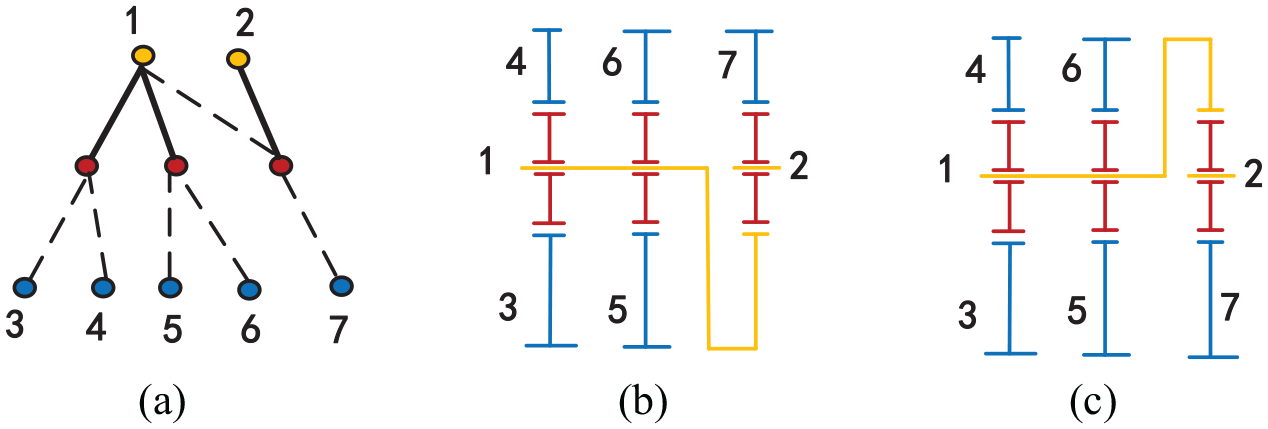
EVT is a 2-DOF mechanism, which can transmit power by mechanical flow and electric flow simultaneously to achieve a variable coupling output. With the development of multi-mode EVT, the 4-DOF 3-row PGM is selected as the basic design structure. The graph model introduced in 11 is adopted for structure representation in this paper. There are three rows of colored vertices in the model: the upper yellow row represents carriers; the middle red row represents planets; and the lower blue row represents sun gears respectively. The relationship of revolute joints and gear joints between vertices are represented by solid lines and dashed lines respectively. Figure 1(a) shows a particular constructive solution of a dual-mode EVT whose graph model is shown in Figure 1(b), and its mode shift logic diagram is shown in Figure 1(c).

(a) A dual-mode EVT, (b) the graph model of the EVT, and (c) mode shift logic diagram.
Where, M/GA and M/GB denote two motors and each of them also can operate as a generator in different mode. C1 represents a clutch and B1 represents a brake.
As is pointed out in Tsai, 18 a necessary condition for two graphs representing two kinematic chains to be isomorphic to each other is that the two mechanisms have identical characteristic polynomials, namely the determinants of the adjacency matrices. Although this method is efficient in computation, it may lead to wrong results. 11 For example, the adjacency matrices of the graphs shown in Figure 2(a) and (b) have the same determinant, but they are not isomorphic.

Two non-isomorphic graphs and their corresponding digraphs: (a) the first graph model, (b) the second graph model, (c) the digraph model corresponding to (a), and (d) the digraph model corresponding to (b).
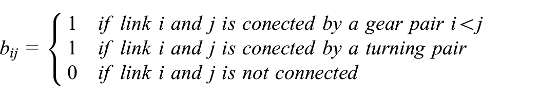
To make all the non-isomorphic topology graphs preserved in the synthesis process, a digraph model is proposed to further check the isomorphism of graphs with the same determinants, as shown in Figure 2(c) and (d) corresponding to Figure 2(a) and (b) respectively.29,30 In the digraph, the outdegrees in the digraphs start from the upper rows to the lower rows when it is a gear pair between two vertices, and there are both outdegrees and indegrees between two vertices when it is a turning pair. In the digraph, the sun vertices have only indegrees, while the carrier and planet vertices have both indegrees and outdegrees. The adjacency matrix
Where,
Combining the isomorphism check algorithm of digraph model proposed in 16 with the polynomial method, the misjudgments of isomorphic topology graphs can be avoided as far as possible. Fifteen kinds of non-isomorphic 4-DOF 3-row PGM topologies are obtained after all the topologies are enumerated, as shown in Figure 3. For each topology structure, there are various constructive alternatives depending on how the lower row distributes its turn of sun gear or gear ring. This method is also applicable to other multi-DOF and multi-row PGM.

Non-isomorphic 4-DOF 3-row PGM topologies.
Rules for adding mode shift elements and M/Gs
Since all the 4-DOF PGM graphs that derived from three single planetary gear sets have been determined, it is necessary to deal with them to achieve multi-mode EVT schemes. The addition of shift elements, including clutches and brakes (C/Bs), is to realize mode switching while the layout of M/Gs is to achieve a continuous power output.
The number of shift elements and analysis of mechanical points
If a u-DOF PGM has

Theoretical modes for a 4-DOF PGM under different number of manipulators.

The angular velocity relation of a planetary gear set between the sun gear speed

Where,
In each working mode, the M/Gs can be operating as a generator or a motor. The speed of a M/G gradually decreases to 0 if it works as a generator, while the speed of a M/G gradually increases if it works as a motor. The EVT switches its work mode when one of the M/Gs rotates at a speed of 0, at this time, the EVT mechanism operates at a most efficient state which called mechanical point where only the mechanical flow can transfer power. For example, the system of the structure shown in Figure 1 works in the second mode when the clutch C1 is connected. The first mechanical point 1 (MP1) of the second mode is generated when the speed of generator B is 0 at the end of the first mode. And the second mechanical point 2 (MP2) is created when the speed of generator A is 0 at the end of the second mode.
A plenty of combinations with shift elements being engaged can generate their corresponding MPs. To formulate the MPs of each combination between the input shaft and the final output link based on the characteristic parameter of each planetary gear set, the equations can be transformed into common matrix form, 31 as is shown in equation (3).

Where,
Rules for adding shift elements and M/Gs
To avoid the results containing idle links and eliminate unreasonable candidate modes, these gear mechanisms should satisfy certain functional constraints. A series of rules to impose in the process of adding shift elements and M/Gs are summarized as follows.
Rule 1: The engine cannot be connected to the brake. There is no mechanical power supply if the input link 3 is braked in the EVT mechanism, as shown in Figure 4.
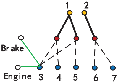
Rule 2: The M/Gs cannot be connected to the brake. The electric power flow has no input when the M/G is braked. The component 3 linked with M/G can be braked in Figure 5.
Rule 3: The M/Gs cannot be connected to the engine or the output link directly. Because the EVT mechanism is a 2-DOF mechanism that requires two input power sources connecting two different components. If a M/G is connected to the output component, there will be no power output when the mechanism is working at a MP state. The structure in Figure 6 should be eliminated.
Rule 4: The M/Gs cannot be connected to the same component if a structure contains two M/Gs, as shown in Figure 7.
Rule 5: Overall rotation should be avoided. Any two links in the same planetary gear set cannot be connected by a clutch. In Figure 8, the case in which there is a clutch between components 1 and 5 will generate overall rotation.
Rule 6: The engine cannot be braked by an intermediary link. There is no mechanical power flow if the engine is connected to the shell by the intermediary link 2, as shown in Figure 9.
Rule 7: The M/G cannot be braked by an intermediary link. There is no electric power if the M/G is connected to the shell by an intermediary link 2, as shown in Figure 10.
Rule 8: A link cannot be connected to the brake and the output component by an intermediary link. There is no power output if the output component is braked by an intermediary link 1, as shown in Figure 11.
Rule 9: The total number of theoretical modes for a combination of C/Bs and M/Gs should be more than or equal to the required number.
Rule 10: The arrangements of shift elements with their corresponding M/Gs should be eliminated when there are no MPs in the generated modes.
Rule 11: The rule of simple shift logic between two adjacent modes should be satisfied to simplify the control.
Rule 12: For smooth mode shift and the addition of fixed gear in subsequent designs, the end MP of the former mode should be equal to the beginning MP of the subsequent mode.1–3
Rule 13: For smooth mode shift, the stage ratio between two adjacent MPs should meet the requirements of a certain scope of value.1,2,26
Rule 14: To realize mode switch between two adjacent modes at the MPs, it is necessary to meet the condition of a continuous change of motor speed for a multi-mode transmission with two M/Gs.1 Two reasonable motor speed curve cases are shown in Figure 12, where
Rule 15: The requirement of planarity should be satisfied to avoid the interference of links.
Component 3 linked with engine in the PGM.

Component 3 linked with M/G in the PGM.

The M/G is connected to the engine or the output.
Two M/Gs linked with same component 7.

Overall rotation in the PGM.

The engine is braked by an intermediary link 2.

The M/G is braked by an intermediary link 2.

The output is braked by an intermediary link 1.

Two reasonable motor speed curve cases.
Configuration design
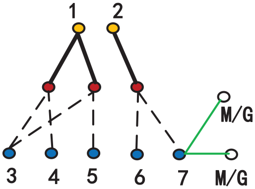
The fifth topological graph in Figure 3 is converted into EVT mechanisms. To achieve automatic calculation for the subsequent process, the links of upper and lower row in the kinematic chain in Figure 13 are coded with numbers 1–7. The gears in the lower row of the third planetary gear set in Figure 13(a) need to be distinguished as gear ring or sun gear. The identification code of link 7 thus consists of two cases, in which the first one indicates that the sign of link 7 could be a gear ring, and the other one could be a sun gear, following the order for the possible structures given in Figure 13(b) and (c).
A 4-DOF PGM and its representation graph: (a) the graph model of the fifth PGM, (b) a PGM stick diagram, and (c) a PGM stick diagram.
Screening of rational shift elements and M/Gs
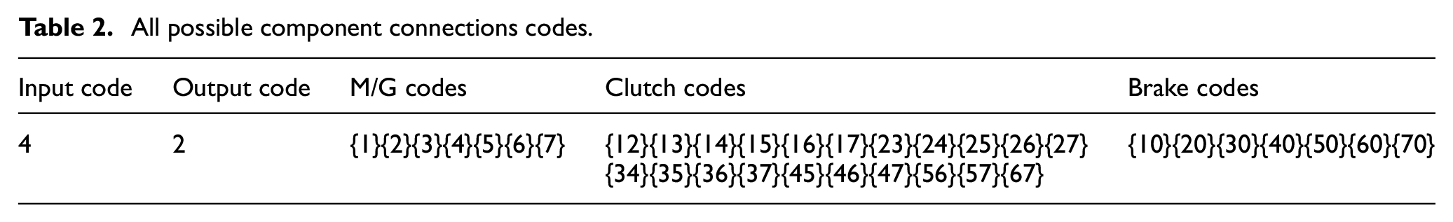
To achieve calculation automatically, different combinations represent different ways the relevant components are connected. For example, {12} means that link 1 and link 2 can be connected by a clutch; {1} means that link 1 is connected to a M/G; {10} means that there is a brake between link 1 and the shell. In addition, the topology structure in Figure 13(b) consists of determining the two of links that component 4 and component 2 are selected as engine and output. All the potential component connections about the topology depiction are shown in Table 2.
All possible component connections codes.
The improper connection of C/Bs and M/Gs can be eliminated according to the rules 1–8 and Table 3 lists the feasible component connections codes. Two clutches (C1 and C2), two brakes (B1 and B2) and two M/Gs (M/G1 and M/G2) are chosen to be added to the PGM for designing EVT with 3-mode according to Table 1. It can be calculated that there are
The feasible component connections codes.

The feasible C/Bs and M/Gs connections codes in Table 3 can be transformed into topologies. Several representative schemes are shown in Figure 14. The structure in Figure 14(a) have its M/Gs codes {1}{3} and shift elements codes {50 60 23 25}; the structure in Figure 14(b) have the M/Gs codes {1}{6} and shift elements codes {30 70 35 67}; the structure in Figure 14(c) have the M/Gs codes {3}{5} and shift elements codes {60 70 36 57}.

Several representative feasible C/Bs and M/Gs connections topologies: (a) a structure with M/Gs {1}{3} and shift elements {50 60 23 25}, (b) a structure with M/Gs {1}{6} and shift elements {30 70 35 67}, and (c) a structure with M/Gs {3}{5} and shift elements {60 70 36 57}.
The determination of mode sequences
Once all the position of mode shift elements C/Bs and M/Gs connections are determined, the entire MPs can be formulated deriving from the ratio equations (2)and (3) of each combination. The calculation processes of two MPs based on the shift elements {70 36} (
Where,


Where,

For MP1,

For MP2,

Two MPs can be obtained by solving equations (6) and (7):

Table 4 shows all the results of MPs based on the shift elements codes {60 70 36 57} with M/Gs codes {3}{5}.
An example of mode connections and MPs.

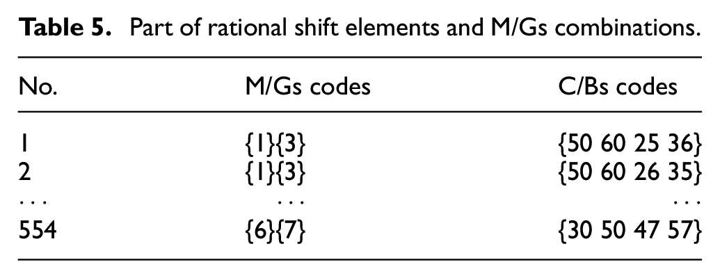
The MPs of all combinations can be calculated in the same way. Only 554 kinds of rational shift elements and M/Gs combinations (Part of them are shown in Table 5) are left after the rule 9–10 are applied to eliminate the schemes whose MPs are not exist, infinite or don’t meet the required mode number. The next step is to determine the mode sequences that can be attained with each 4-DOF 3-row PGM. These sequences depend on the values of their characteristic parameters and the C/Bs codes.
Part of rational shift elements and M/Gs combinations.
The characteristic parameters
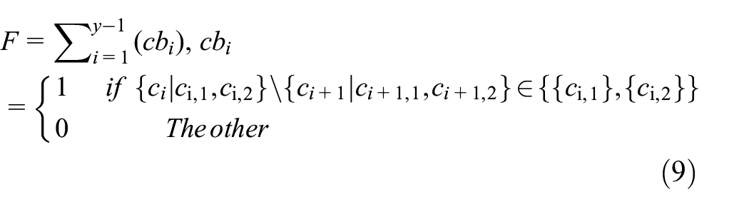
Where, y denotes the total number of modes. The C/Bs codes in Table 4 are represented by
After permutating all the schemes based on their shift elements and M/Gs combinations in Table 5, there are only 11,150 feasible permutations left when equation (9) is used. Part of rational schemes are shown in Table 6.
Part of rational shift element combinations that meet the rule of simple shift logic.

According to the rule 12, there should be a common MP between two adjacent modes, that is, the end MP of the former mode is equal to the beginning MP of the subsequent mode. Equation (10) is used to screen out those schemes that do not meet the MPs connective condition.

Where, the MP1 and MP2 in Table 6 are represented by
Part of rational shift element combinations that meet the rule 12.

The ratio step between two adjacent MPs should meet a certain range [2, 3.2].1,2 The function for the No. 73 scheme in Table 7 can be established as an example, as shown in equation (11).
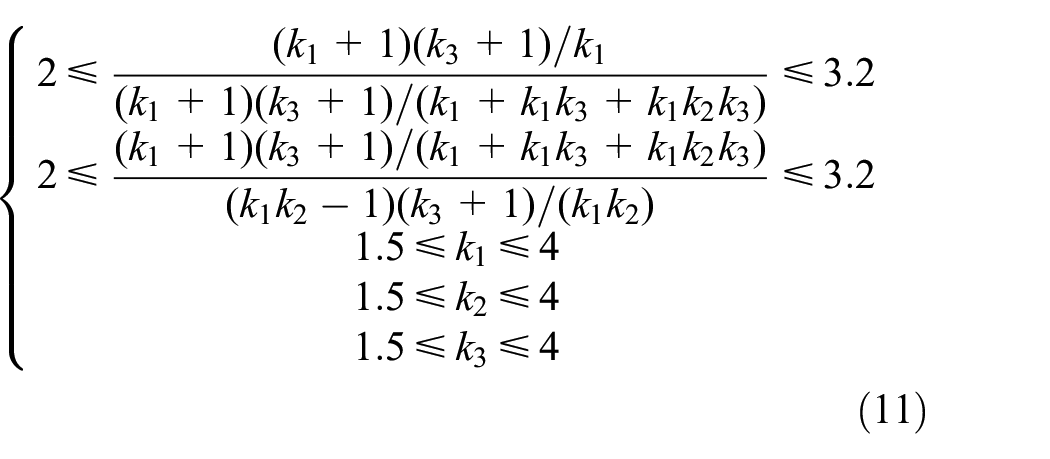
It is difficult to solve equation (11) and determine the scope of values for each characteristic parameter because there are many candidate structures with different forms of multivariate nonlinear functions. The method of Monte Carlo simulation is adopted to create 10,000 combinations of characteristic parameter
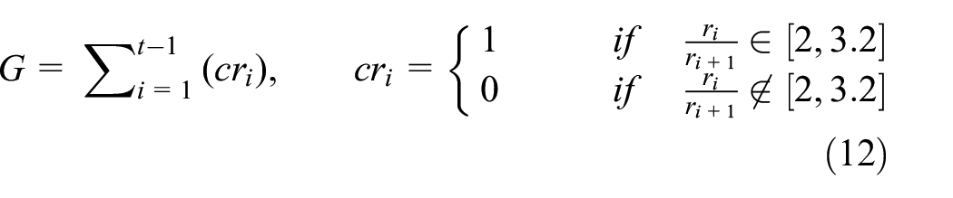
Where, t is the total number of MPs,
The next condition is to achieve a continuous change of motor speed for a multi-mode transmission with two M/Gs between two adjacent modes. Figure 15 presents an example that cannot meet the constrain rule 14. Its mode shift elements and MPs are shown in Table 8 (✓ means the related mode shift element connected) and Table 9. Its operating states of two M/Gs in each mode should be shown in Table 10.

An example that cannot meet the rule 14.
Mode shift elements of Figure 15.

MPs in different mode of Figure 15.

Operating states of two M/Gs in each mode.
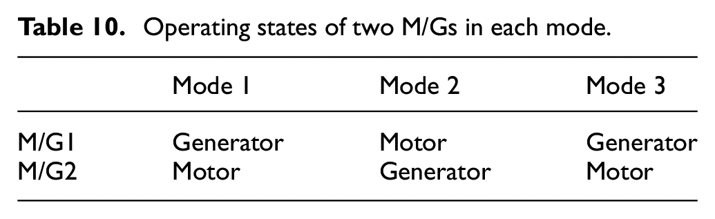
From Tables 8 and 9, the structure in Figure 15 meets all the rules before rule 14. Such as, the simple shift logic between adjacent modes and there is a common MP between two adjacent modes. But it cannot achieve a continuous variable coupling output speed when it works at mode 1, because M/G2 is braked and cannot work while C2 and B2 is connected.
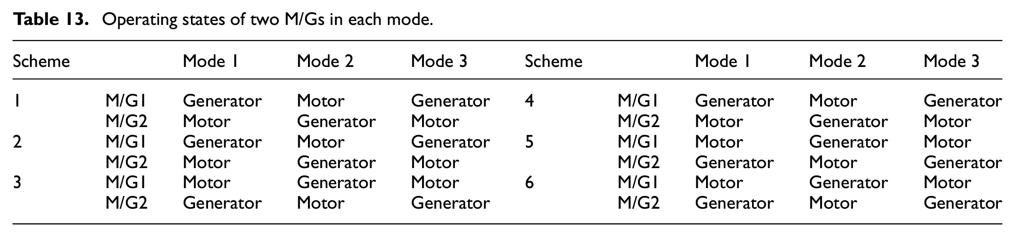
Six rational schemes remain after the 73 schemes are checked by the previous rules 13–15, as shown in Figure 16. Their working state of mode shift elements and MPs are shown in Tables 11 and 12. And the operating states of two M/Gs in each mode are listed in Table 13.

Reasonable 3-mode EVT schemes based on 4-DOF 3-row PGM.
Working state of mode shift elements of the six new EVTs.

MPs in different mode of the six new EVTs.

Operating states of two M/Gs in each mode.
Parameter optimization
Six rational sequences along with their MPs are obtained in the previous sections. A practical analysis of the foregoing results also requires one to estimate the efficiency of each scheme. This is particularly important when these schemes work at MPs, since such a case may have been achieved by considerably sacrificing efficiency. Therefore, the efficiency of each EVT is estimated by the method 34 when it works at the MPs, as shown in equations (13)–(16).


Where,

Where,
Another important consideration for the six EVTs is the determination of the MPs values. The second objective function

Where,
This paper adopts a computational algorithm of the Nondominated Sorting Genetic Algorithm-II (NSGA-II) to optimize the MPs with characteristic parameters in equations (17) and (18), because of its high calculation efficiency and good performance of convergence.35–37 Table 14 shows the optimal values of each characteristic parameter found by NSGA-II computational model with a level of precision 0.01. Their calculated MPs values of the six new schemes are listed in Table 15.
Characteristic parameter values of the six schemes.

The MPs values of the six new schemes.

From the results about the six new novelty EVTs with 3-row PGM that come from the same basic 4-DOF structure in Figure 13(b), all of them satisfy the fundamental constraints. Each of the 3-mode EVTs containing two brakes, two clutches and two M/Gs can achieve a continuous variable output speed in Figure 16. At the same time, the two M/Gs should switch their operating state between generator and motor in each mode as calculated in Table 13. What needs to be emphasized is that the designed scheme 1 has the same structure and MPs as the typical patent in Holmes. 3 The requirement of simple control is also satisfied because there is only one mode shift element need to be operated between two adjacent modes from Table 11. Tables 14 and 15 show that the optimized characteristic parameter and MPs values and all of the stage ratios between two adjacent MPs can meet a certain range [2, 3.2]. Moreover, the scheme 4 has the same MPs as the scheme 1 but different in M/Gs and shift elements connections. The scheme 3 and scheme 6 also have the same MPs and different structures.
The results reveal that the feasibility and rapidity of this proposed method is validated. The whole calculation process can be fully automated by coding each component of the PGM, C/Bs, and M/Gs connections. It is more progressive and efficient than the previous manual drawing design. To find the best solutions among the large number of potential candidates, the summarized 15 constraint rules provide a direction with guiding significance and greatly improve the design efficiency. As the values of
Conclusion
The objective of this study is to design new multi-mode EVTs that attain proper MPs ratios with high efficiencies at the same time as having an acceptable structure. The proposed method can solve the problems with computational complexity caused by the large number of potential shifting elements and M/Gs combinations, and several satisfactory schemes are obtained with their calculated characteristic parameters automatically. The systematic design method for 3-mode EVT schemes based on 4-DOF 3-row PGM can be summarized as follows.
(1) The redundant isomorphic PGMs are eliminated after the method combining digraph mode with the determinants of adjacency matrices is used and 15 non-isomorphic 4-DOF 3-row PGM topologies are reserved as the basic structure for the following design steps. It helps improve the efficiency of designing new multi-mode EVT schemes.
(2) To reduce a large amount of redundant calculation, 15 leading rules for C/Bs and M/Gs configurations in the 4-DOF 3-row PGM basic structure are presented. And the speed matrix equations under different C/Bs and M/Gs combinations are utilized to achieve all the rational MPs with characteristic parameters when the mechanism works at the moment of each mode shift. The screening conditions associated with the MPs greatly narrow the design scope of new EVT schemes, especially for the determine of rational mode sequences.
(3) The method of Monte Carlo simulation is adopted to generate combinations of
The results indicate that the automatic and systematic method has achieved efficient calculation and its feasibility is verified. In the future work, the EVT with more modes and the adding of fixed gears for EVT need to be further developed.
Footnotes
Handling Editor: Chenhui Liang
Declaration of conflicting interests
The author(s) declared no potential conflicts of interest with respect to the research, authorship, and/or publication of this article.
Funding
The author(s) disclosed receipt of the following financial support for the research, authorship, and/or publication of this article: The research work is funded by the following funds: National Natural Science Foundation of China (Grant Nos. 51775488 and 52175219), the Fundamental Research Funds for Central Universities (Grant No. 2232019A3-11).