
Abstract
The article presents the results of theoretical and experimental research of acoustic emission of friction units during rolling-sliding friction contact. The purpose of this study is the development of a method of accelerated assessment of contact fatigue strength with the application of acoustic emission during friction contact. The application of acoustic emission method reveals periods of energy state of the material: the activation, the damage accumulation, the transition to the initial fatigue damage. Pulse loading up to the maximum possible value was used for activation of damage accumulation process on the friction surfaces. Specific destructive energy for one load cycle was used as the fatigue strength assessment criterion. The developed technique allows to quantify the fatigue strength in analogy with the methods of such evaluation with the help of fatigue machines for testing at cyclic loads.
Keywords
Introduction
The service life of friction units of various devices and aggregates in some cases is determined by the ability of the material to withstand fatigue destruction, which is characterized by the value of contact strength of the material. Among the methods used to increase the contact strength of materials, chemical-thermal methods of cementing treatment of the surface are widely used. 1 Nitriding techniques are also used, though less frequently than cementation. This is probably due to a limited number of studies of the influence of the nitriding effect on the value of contact strength of materials, especially for ion-plasma nitriding methods. These methods have significant differences and advantages over traditional furnace gas nitriding methods,2–9 namely:
- significant time reduction (2–3 times) of diffusion nitrogen saturation of the surface layer of alloys based on iron with a total reduction of the processing cycle time by up to 3–5 times.
- complete avoiding of hydrogen embrittlement, etc.
Another reason that inhibits the introduction of a promising method of ion-plasma nitriding into manufacturing is the significant cost and long-time of fatigue testing at rolling friction of such reinforced materials to determine the effectiveness of the proposed measures. To fix this problem, the development of accelerated assessment methods is required. Nowadays the application of the energy approach is the most effective base for the development of the accelerated methods for fatigue strength evaluation.10–12 Even though energy methods for assessment of wear parameters are used in tribology for more than half a century, until now the experimental studies of the change in the accumulated energy of surface layers during fatigue strength tests have practically not been carried out – there were no appropriate methods and technical means. This problem can be solved using a control method based on the analysis of parameters of acoustic emission signals (AE) that come directly from the friction zone. 13
Analysis of recent achievements and publications
Many works are currently devoted to the kinetics of damage and destruction of solids.10,11,14 Achievements in the field of fatigue strength assessment are widely summarized in the work. 11 Now in the literature a large place is given to review publications, the creation of various classifications and criteria for assessing the tribotechnical characteristics of materials, primarily aimed to the methods of conducting comparative tests for fatigue wear resistance.11,15,16 In these works, fatigue wear is characterized by the existence of a hidden latent period, during which there is no visible destruction of the surface layer of material, but there is a gradual accumulation of defects.15–17 When a certain concentration of micro-injuries is reached, a phase of rapid destruction occurs, when the “tired” material of the surface layer is dispersed (converted) in the form of wear particles. 18 It is observed that the density of internal energy is a single integral characteristic of the thermodynamic state of the surface layer of material. 19 At the same time, the main role in damage was assigned to the hidden energy of plastic deformation. 11
The main problem of the energy theory of destruction, that it uses such parameters of damage, which are inherently not observed.19–22 The modern development of non-destructive control methods, namely the AE method, makes possible to control the processes of both small and multi-cycle fatigue at all stages of its development.23–26 To effectively estimate the technical condition of tribosystems (TS) in the process of laboratory tests and operation, it is necessary to use indicators that allow determining the rate of accumulation of damage and the transition to various mechanisms of destruction (wear), including fatigue damage. Indicators that determine the rate of wear are various energy criteria which reflect the process of energy dissipation (change) during friction. 27
At the same time, the acoustic emission information and diagnostic system (IDS) developed by the authors of this article13,28 is used in many works for solving these problems. Technical characteristics of IDS are given in Stadnychenko.
29
As a criterion for assessment of the damage measure, the parameter of the average AE power during the registration time of 20 ms is taken. The results of the assessment of the wear rate with the application of the AE method13,28 allowed the authors to assess the sensitivity of this method when recording the wear of the analyzed friction units. It is within the range of specific emission activity change
The developed technique for processing acoustic emission signals and determining the wear mechanisms allows recording the wear rate starting from the separation of the first wear particle in the tribosystem in AE power units’ measurement. That gives the practical base for the development of a method for accelerated comparative assessment of fatigue damage indicators.
Goal of research
The purpose of this study to analyze the effect of acoustic oscillations generated at rolling-sliding friction contact with the purpose to develop an accelerated comparative assessment of contact fatigue strength indicators during friction testing of structural materials. The relevance of this work is due to the need of a significantly increase of the service life of high-load drive units (with an increased service life of 12,000 h without overhaul) of aircraft gas turbine engines. This required replacing the traditional method of gear teeth strengthening by cementation with a new, more advanced, and sophisticated method of strengthening – nitriding. To decide on the possibility of using such a replacement of the strengthening method for the contact surfaces of the friction units, it became necessary to conduct accelerated comprehensive assessment on fatigue of the friction units.
Presentation of the basic theoretical material
Based on the analysis of main achievements and publications that is made before, it was determined that the tribosystem impulsive loading to the maximum possible values could be the factor that reduce the test time of friction units.
Considering the microstructural organization of the surface layer of tribosystem materials under friction conditions at high contact loads, it can be determined (Figure 1) that two areas of damage accumulation are formed during fatigue wear: the first is concentrated in the thin surface layer 1, which accumulates defects, and breaks in the low-cycle fatigue mode, and the second, spreading to a greater depth into the layer 2 and is responsible for the kinetics of the development of contact friction fatigue, which proceeds in the multi-cycle mode. 10

Microstructural arrangement of the surface layer of tribosystem materials under friction conditions with large contact loads: 1 – transfer layer (secondary structures), 2 – small-cell fragmented structure, and 3 – structure with irregular cells.
Select the area on the surface S then, at depth H (Figure 2), effective volume of material Vm ef, participating in the contact interaction will be equal to Vm ef = SH. In this volume in the conditions of contact interaction, structural changes (material degradation, accumulation of defects) occur with the speed of contact interaction

Appearance of samples and waveguide with sensor for reception of acoustic emission signals through oil wedge (a), general view of contact interaction of samples and waveguide during tests (b), reception of AE signals via hydraulic wedge (c).
Obviously, the destruction and subsequent destruction of the specified volume of material Vm cr takes place in accordance with the degree of damage z(t) of the surface layer of the structural material, which depends on the balance between the external supplied energy and accumulated energy in this volume 10 :

where
The amount of energy
In accordance with the structural and energy theory of fatigue strength, formulated by Fedorov V.V. under conditions of contact interaction, two processes occur in parallel: energy accumulation and its scattering (dissipation). Most of the energy (more than 80%) is converted to heat, and the rest accumulates in the surface layer

where
The magnitude of this energy
With given expression (2), expression (1) can be written as:
Thus, the analysis of expressions (2) and (3) gives us the possibility to consider that the criterion for the fatigue strength of materials under conditions of contact interactions is the ratio of the energy flow (power) that affects the surface of the part to the critical density of the energy flow (power)
Considering the possibility of determining the critical number of contact cycles at the time of destruction of the surface layer, and using the function describing the kinetics of damage development (
where
The analysis of expressions (2) and (3) provides an understanding of the possibility of accelerating comparative tests for contact fatigue strength. The first way: to increase E0 (2) significantly. This value is directly related to the value of the contact load. The second way is to increase the critical rate of external impact
Thus, the main stage of accelerated tests is impulse load up to maximum values σmax. Implosive loading captures a layer of several tens of microns – depending on the surface relief and contact stresses. In this layer, the bulk of the friction forces work is dissipated.
Now this issue has not yet been studied enough, but four main channels of dissipation can be distinguished (as the thickness of the layer grows)11,33:
breaking of adhesion bonds between surfaces.
elastic stresses relaxation from interacting irregularities of surfaces (i.e., transition of elastic stresses into long-wave phonons).
conversion of mechanical energy into thermal energy.
stress relaxation because of plastic deformations according to the dislocation mechanism. 11
The total energy flows through the surface layers are quite large. According to the formula of V.I. Vladimirov, the amount of energy that passes through the surface layers during friction is 34 :

where P– power supplied to tribosystems;
V m ef– effective volume of interaction;
σ– contact stress from absolute load during friction;
V fri– linear velocity of mutual movement of specimen;
H– thickness of the layer in which the interaction takes place.
Part of this energy that is supplied to the tribosystem (considering its peculiarities) is normalized by the coefficient of friction μ 10 :
where
If in our case the thickness of the layer for nitrified and cemented specimens is H ≈ 0.2 mm, and the friction stress σ ≈ 1140 MPa, then at the shear rate of the Vfri ≈ 0.65 m/c at the contact interaction for each cycle and the measured friction coefficient the μ ≈ 0.04, the specific energy power supplied to the effective volume of the tribosystem per cycle will be about Esup1 ≈4.8 × 10⁶ J/m3. The total supplied energy depends on the number of cycles before destruction. This number depends on the rotation speed of the friction machine, therefore, considering (6) can determine

where
If even a small fraction of this energy passes into the latent energy (latent) that the structure of the surface layer has accumulated, then the material enters the excited state, which makes it possible to accelerate the achievement of a critical level of the internal accumulated energy and the transition to destruction. 11 At impulse loading, the transition to the excited state occurs under external influence (force, flow, etc.) with an intensity higher than some critical. This means that the transition is preceded by the accumulation of some elementary excitations, the concentration of which reaches a critical value. Considering the structural and energy approach to destruction in the conditions of contact interaction of structural materials, the destruction is due to the competition of two interconnected, but opposite trends: an increase in the density of damage and a decrease (release) of this energy due to relaxation. And when the critical density of latent energy is reached, destruction occurs. Thus, as a result of the modeling, the conditions for conducting of accelerated tests were formulated for the comparative assessment of fatigue damage indicators of materials strengthened by cementation and ion-plasma nitriding using “Avinit N” technology.
The experimental research
Tribological studies on comparison assessment of contact fatigue strength in rolling friction with slippage were carried out with the application of the modified friction machine 2070 CMT-1. Tested friction pairs have “disk-to-disk” structural design (Figure 2). The test procedure is standardized (GOST 30480-97). 35 The shape and dimensions of triboelements for tribotechnical tests, which are shown in Figure 2(a), also met the requirements of GOST 30480-97.
Before the tests, the tested specimens were washed with Kalosha gasoline GOST 2603-71, dried at a temperature of 70°C, and weighed on analytical scales BLR-200 with an accuracy of 10−4 g.
During the experiments, in accordance with the requirements of GOST 30480-97, the following data was recorded:
- moment of friction (recalculated into coefficient of friction), the value of which was judged on mechanical losses in the tribosystem. Absolute error of friction moment measurement was ±3%.
- the temperature of the elements was continuously recorded in real-time tests directly in the friction zone using the Nimbus-760 pyrometer. Absolute error of temperature measurement was ±1%
Additionally, the wear rate was measured by acoustic emission (AE).23–26 This method allows you to record the wear rate over time from 20 ms in relative units. Thus, wear is recorded from the moment of separation of the first particles of material from the friction surface in real time during the entire test period.
The upgrade of the 2070 CMT-1 friction machine was made to increase a value of load applied to the tested specimen by changing the fastening of the carriage lever mount. Due to this, it was possible to increase the impulse load up to 4500 N thus to achieve contact loads of σ ≈ 1140 MPa. Recalculation was carried out using Hertz’s formula in a simplified version. This increased level of contact loads made it possible to estimate the relative contact fatigue strength of friction specimens at cyclic loads under rolling friction conditions with slippage.
To control a value of load applied to the tribosystem, the 2070 CMT-1 friction machine was additionally equipped with a load control and regulation module. 29 As well as an electromechanical device for changing a value of the load applied to the tribosystem, which allows automatically change the load in a wide operational range of 0–4500 H. General scheme of control of load value applied to tribosystem is given in Stadnychenko. 29
Four friction pairs of the same type were tested. Tested friction pair is “disk-to-disk.” Disks have diameter d = 50 mm and height h = 12 mm (Figure 3), dimensions are standards for friction machines 2070 SMT-1 (2070 CMT-1) and SMC-2 (CMЦ-2). Material of specimens is steel 20X3MBF (20X3MBΦ)/20Cr3MWV GOST 20072) (Table 1).

AE spectral power diagram during multi-cycle fatigue tests: (a) cementation and (b) nitriding.
Initial chemical composition of friction surfaces. Tribosystem: steel 20X3MBF (20X3MBΦ) – steel 20X3MBF (20X3MBФ).

The material is selected based on the condition that this steel is used in the real tribosystems of aviation aggregates and can be strengthened by both cementation and nitriding. Lubrication mode: oil bath, lubricating oil M-8B, GOST 10541 (SAE20, API SD/CB) by immersing the bottom sample in an oil bath (Figure 2(a) and (b)). The lubricating oil, which was trapped by the bottom sample, hold securely on its surface, enters the contact area, and forms an oil wedge in the gap between the waveguide and the bottom specimen when moving. Waveguide shape ensures delivering of required amount of lubricating oil and its continuous deliver to contact area. AE signals were received through an oil wedge between the waveguide and the bottom sample (Figure 2(a)).
Test conditions: speed of rotation of the lead specimen – 500 rpm; slipping between specimens − 20%; absolute load – 4500 N (corresponding to the specific load calculated according to Hertz’s formula in simplified form σmax = 1400 MПa); load speed is constant Vload = 450 N/s; loading time – 10 s; test time – up to the moment of increase a value of power of acoustic emission of AE, W (in specific units) more than 10 times from its level at normal mechanochemical wear, presumably, up to the beginning of primary appearing of fatigue failure. 36
Before tests the contact surfaces of the specimens were strengthened: by gas cementation according to traditional technology, grinding after hardening; ion-plasma nitriding.7–9 The essence of strengthening of the contact surface of material with an application of ion-plasma nitriding treatment is based on the fact that the nitrogenous layer is formed with a stably equilibrium microstructure without a fragile surface structure on the surface of the material and, as a result, hardness increases. There is no curvature of the units, preservation of the initial geometric dimensions while accelerating nitriding by 3–5 times.7–9 The main advantage, which is declared in the patent and requires the confirmation, is the possibility of obtaining a special controlled structure of surface layers of metals for specific operation conditions of tribosystems. If even a small part of this energy passes into the latent energy (latent) that the surface layer structure has accumulated, the material enters the excited state. 19
For the considered modalities of impulse contact effects, this condition can lead to the following:
(1) For specimens strengthened by nitriding, increasing the degree and rate of deformation create conditions for the transition of the structure from crystalline to amorphous state. External friction leads to amorphization of the surface layer by nitrogen atoms to form new phases, including non-eq8. It should be expected that for nitrogenous surfaces, the cessation of external influence will lead to a rapid rearrangement of the structure, and therefore to the relaxation of residual and active stresses. This will be the main difference between the dissipation channels of the external supplied energy during friction for nitrogen specimens (from cemented ones).
(2) In the case of cementation, strengthening occurs with simultaneous accumulation of energy at the grain interface, which subsequently lead to the growth of microcracks.
These conclusions are the basis for accelerated tests of the declared tribosystems for contact fatigue, with the expected advantage of strengthening with nitrogen by “Avinit N” technology.7–9
This hypothesis is based on the structural-energy theory of strength, according to which V. V. Fedorov proposed such a condition for destruction in integral form19,33:

where u– some parameter of damage;
u 0– damageability initially inherent in the material (various initial defects of the structure);
t *– time of material operation before destruction;
u(t*) – damageability accumulated in the material during t* with rate
In this expression, the damageability of the material is divided into two parts: the initial original damageability of the material u0 and the accumulated damageability during time t* at a rate of
Considering the thermodynamic concept of material destruction during plastic deformation and wear, the destruction is due to the competition of two interconnected, but opposite trends in the growth of damage density and the decrease (release) of this energy due to relaxation. And when the critical density of latent energy is reached, destruction occurs.
Based on the main provisions of the energy theory, the physical content of the damage parameter u in our case can be represented as the specific power of dissipated energy in one load cycle
The developed technique is as follows. At the first stage of this procedure, the impulsive loading applied to the tribosystems up to the maximum possible values and a diagram of change of AE signals before the start of fatigue destruction is recorded, power of AE (W) increases to values more than 100 specific units. In the second stage, the number of cycles before the start of fatigue destruction is determined. At the third stage specific energy of dissipation is determined in one load cycle. This difference is equivalent to the damage parameter u (9).
In accordance with this, we propose to evaluate the fatigue strength with the specific energy of dissipation for one load cycle. For the tribosystem with nitrogen strengthening, this parameter

where
Using this parameter, it is possible to compare various structural materials and methods of their strengthening (to select more efficient ones) during accelerated fatigue strength tests.
The chart view of the acoustic emission diagram during tests of friction pairs which are strengthened by cementation and nitriding is shown in Figure 3. The figure shows the characteristic view of the AE spectral power diagram for each of the three typical conditional test stages:
- “The start” corresponds to the load stage.
- “The middle” corresponds to the stage of a stable mode of accumulation of damage.
- “The completion” corresponds to the stage of initial destruction of a tired nature.
In the process of testing, it was established that each test cycle consists of three characteristic stages: the first – the loading stage; second – access to a stable mode of accumulation of damages in the surface layer; the third is the transition to the initial destruction of a fatigue nature (Figure 3). The average number of cycles before the onset of fatigue failure phenomena and tribotechnical parameters values for four pairs of specimens strengthened by cementation and nitriding are given in Table 2.
Number of cycles before fatigue failure and tribotechnical parameters values for four pairs of samples.

After the impulsive loading, the external applied forces lost the role of the cause of destruction and became only its condition which is necessary to start internal dissipative mechanisms. The work of destruction of the surface layer is carried out by internal forces which are formed because of energy exchange between the dissipative system and the environment. After testing, the friction surfaces of all specimens were evaluated at an increase of ×500. Specimens that worked in pairs and have the most characteristic and extensive damage were taken. The metal-physical research was carried out at the Ivan Kozhedub Kharkiv National Air Force University, as well as at Motor Sich JSC (Zaporozhye, Ukraine). Surface fractography after tests are shown in Figure 4.
Surface fractography of specimens after tests: (a) driving and (b) bear.
It is found that output reliefs of contact surfaces of specimens with cementation are patched, output reliefs of contact surfaces of specimens with nitriding have traces of initial reliefs of pre-treatment.
The contact surfaces of all specimens have multiple point shells without protruding the metal along the contour, probably representing the foci of fatigue flaking.
Microstructural studies of specimen material have found:
- For the cemented specimen, on the side of the contact surface there is an ulcerative crack and small holes from bursting, the depth of which is ≈0.005 mm (Figure 5). The actual depth of the cemented layer is ≈1.2 mm.
- For the nitrided driven specimen on the side of the contact surface there are ulcerative cracks and holes oriented along it from the drilling, the depth of which is approximately 0.010 mm (Figure 6).

Traces of flaking on the cemented specimen from the side of the contact surface: (a) ×500, longitudinal section and (b) ×200, cross-section.

Traces of flaking on the nitrogen specimen from the side of the contact surface: (a) ×500, longitudinal section and (b) ×500, cross-section.
The microstructure of the nitrogenous layer – in the outermost layer there is

Microstructural studies of the surface layer of nitrided specimens: (a) bear specimen, nitration layer (×6.5) and (b) bear specimen, microstructure of nitriding layer (×500).
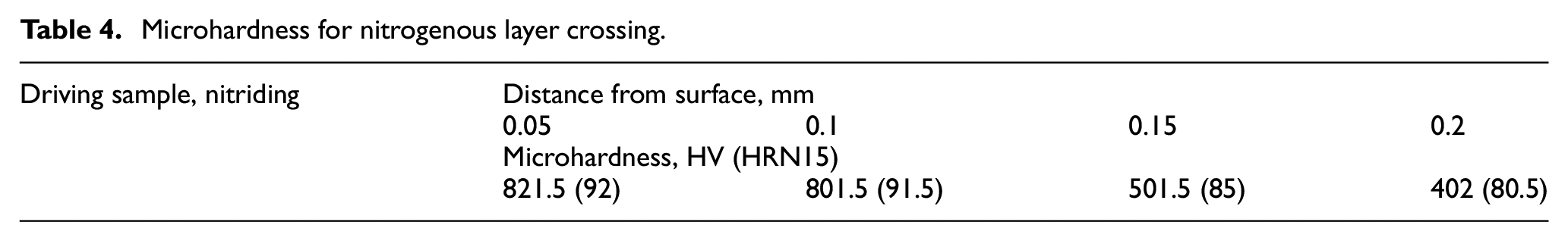
Microhardness was determined by cross section of reinforced layers. The results are presented in Tables 2 and 3. Microhardness was measured using a hardness measurement instrument PMT-3 in accordance with interstate standard GOST 9450-76 (similar to ISO 4516:2002). The device is designed to determine microhardness at low loads (up to 19.6 N) using a standard Vickers diamond pyramid with an angle at a peak of 136°. Load range − 0.098–19.61 N, exposure time − 10–15 s, microhardness measurement range − 5–2500 MPa. The device has a fully automated measurement process, for the initialization of which it is enough to set the force value and select the necessary place on the contact surface of the triboelement using an integrated microscope (the magnifying power ×100 and ×400).
Microhardness for cemented layer crossing (driven specimen).

A load mechanism with reduced friction is used in the hardness measurement instrument, which ensures the constancy of the applied force and increases the accuracy of tests. A skewed (indirect) assessment of microhardness was performed on the depth of the working layer of samples after tests. For this purpose, microhardness was measured at loads of 0.5; 1 and 2 N. The recalculation of the diagonal in terms of the depth of the print is made according to the formula h = d/7, where h is the depth of the print, d is the diagonal of the print after its unloading. Measurement error is 2%.
The microhardness was determined as the average of 10 measurements. The effective depth of the cemented layer corresponding to 500 HV is approximately 1.15 mm. The hardness of the core of the lead cemented specimen is 39.5 HRS (Table 3). The effective depth of the nitrogenous layer corresponding to 500 HV is about 0.15 mm. The hardness of the core of the bear nitriding specimen is 29 HRS (Table 4).
Microhardness for nitrogenous layer crossing.
Fractographic studies of point shells without protruding metal along the circuit were carried out using an electron microscope with an increase to ×5500, as a result of which concentric and stepped tempering lines were found on the bottom of the shells, which is a characteristic sign of destruction along the fatigue mechanism (Figure 8).

Fractographic studies with indicated tempering lines: (a) inhibited cemented sample, ×3500 and (b) inhibited nitrided sample, ×5000.
Results of fatigue strength studies during long-term friction tests
To confirm the reliability of the results obtained during accelerated tests, long-term tests of the investigated tribosystems (960,000 cycles, which corresponded to 32 h of operation in periods of 8 h with 16 h breaks) were carried out under the same conditions described above. Weight wear for this test period was accepted as the estimate. In this case, the integral characteristic of wear resistance under conditions of high contact stresses was evaluated.
This characteristic included weight loss due to normal mechanochemical wear and due to fatigue flaking. Under such test conditions, it is not possible to separate these two wear components.
Three friction pears with certain numbers were tested. The results are shown in Table 5 and 6. No scuffing were detected during the entire test period for any pair of specimens. During the tests, the average surface temperature and friction moment were recorded, which was recalculated into the friction coefficient (Table 5). Before and after the tests, specimens were weighed on analytical laboratory scales of VLA 200 with an accuracy of 10−4 g. Wear of driving and bear samples and total wear were determined (Table 6).
Results of the friction coefficient and temperature measurement.

Designation of specimen numbers that were later used for metal-physical studies.
Results of determination of weight wear of specimens.

At the time of separation of the large wear particle according to the pitting mechanism, a jump is observed in the friction coefficient change diagram, the duration of which is 10–12 min. In our opinion, this is due to the mechanics of destruction. First, bulging occurs, and then separating the volume of the material. After that, the friction moment is stabilized and the overlying along the defect boundary begins. Thus, a characteristic breakage is gradually formed on specimens with cementation.
The obtained data indicate that specimens strengthened by nitriding according to the technology7–9 have higher wear resistance indicators compared to cementation, considering the fatigue mechanism of surface destruction (by 10 times).
Also, fractographic studies show (Figure 9) that local bursts of a fatigue nature are observed on friction surfaces (for nitrogenous samples with a depth of 0.006–0.009 mm, for cemented ones – the depth increases to 0.015–0.03 mm). Analysis of surface micrographs and visual observation over the entire surface of the specimens showed that the cemented driving roller loses weight mainly because of fatigue damage and partly due to mechanochemical wear. In the bear roller, weight loss mainly occurs due to normal mechanochemical wear and partially fatigue.
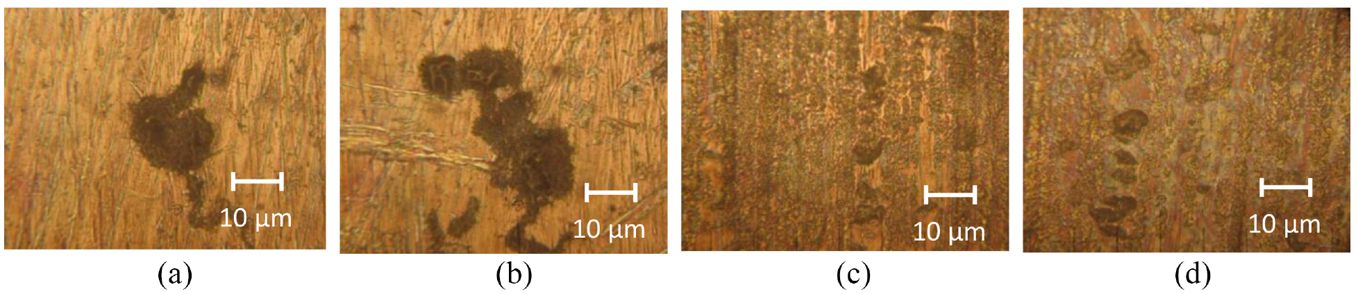
Fractographic studies of friction surfaces after tests (×534): (a, b) characteristic damages for rollers with cementation and (c, d) characteristic damages for rollers with nitriding.
Moreover, the depth of damage in this case is much greater (Figure 9(a) and (b)). In nitrogenous specimens, weight loss for driving and bear specimens occurs equally due to mechanochemical wear and fatigue damage (Figure 9(c) and (d)).
Figure 9 shows the characteristic appearance of local flaking (pitting) of a fatigue nature on the working surfaces of specimens after 32 h of testing: Figure 9(a) and (b) – the characteristic appearance of damages for rollers with cementation, Figure 9(c) and (d) – the characteristic appearance of damages for rollers with nitriding. Such damages were observed across the entire width of the surface which was involved in friction.
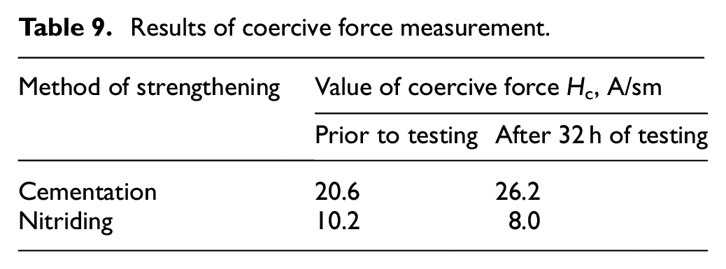
To confirm the hypothesis of the reasons for the advantages of structural engineering of the surface with nitriding over the surface with cementation, microhardness measurements were made in the depth of the surface layer in the range up to 0.2 mm (Tables 7 and 8) 18 and coercive force 37 (Table 9). The study was carried out before the tests and after 32 h of operation.
Microhardness results Hμ prior to testing.

Microhardness results Hμ after testing with 960,000 load cycles (32 h of operation with a working interval of 8 h per day).

Results of coercive force measurement.
By analyzing these results, we can draw the following conclusion: in the cementite layer after 960,000 cycles, there is a significant decrease in microhardness due, in our opinion, to the accumulation of microstructural level fatigue defects in the surface layer. This is the reason for the increase in the integral amount of wear (ordinary mechanochemical wear plus pitting destruction).
For nitrided specimens, microhardness values remain at substantially the same level as confirmation of surface layer amorphization, and consequently significantly less accumulation of fatigue defects.
Measurements of the coercive force (Table 9) also confirm these conclusions: the number of grain boundaries in the microstructure of the cemented layer increases, and in the nitrogen layer – even slightly decreases due to amorphization of the surface layer during long-term operation. This is observed quite well on the micro-blips presented later (Figures 11 and 12).
Thus, the results of comparative tests showed a significant advantage of samples with nitrogen strengthening compared to cementation. In terms of coefficient of friction, the tribosystem with nitriding strengthening is slightly inferior to the tribosystem with cementation in the first cycle of operation (8 h). This, apparently, is due to the appearance in the process of working on the surfaces of samples with cementation, a characteristic “braided” relief. After 32 h of testing, friction factors for both test tribosystems are equalized (Table 5). The integral value of wear of samples strengthened by nitriding is more than 10 times smaller compared to cementation strengthening.
Results of metallographic research after long-term fatigue strength tests
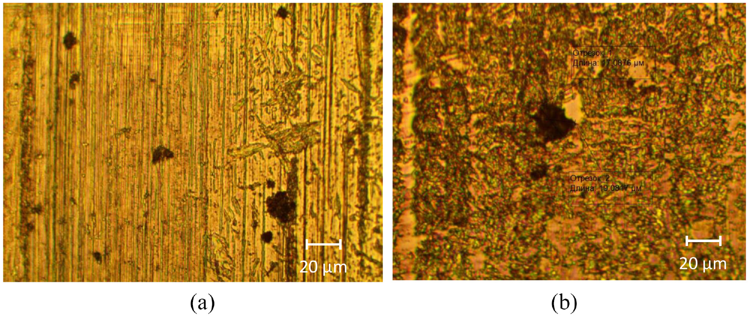
Metallographic research of 6C/10C (cementation) and 5A/1A (nitriding) rollers (specimens), were carried out by specialists of “Motor Sich JSC” (Zaporozhye, Ukraine). The inspection of 6C and 10C specimens, with the application of binocular and optical microscopes found that the relief of latched surfaces is characteristic for rolling-sliding friction contact, which is accompanied by the formation of surface reliefs and depressions in the form of point shells in all areas which are involved in the contact.
The inspection of 5A and 1A specimens with the application of binocular and optical microscopes found that the relief of the initial mechanical treatment is visible on their surfaces, the reliefs and depressions in the form of point shells, characteristic of surface exfoliation and flaking, in all areas involved in the contact, are presented. To confirm the nature of the shells on the surfaces of the specimens, a fractographic research was carried out using an electron microscope with an increase to ×5500. As a result, it is confirmed that the shells are traces of fatigue exfoliation and flanking: lines which are characteristic for fatigue destruction are observed in the bottom of the shells (Figure 10).

Fractographic studies: (a) specimen 6C (×1500); (b) sample 6C (×3500); (c) sample 10C (×1500); (d) sample 10C (×2500); (e) sample 1A (×2700); (f) sample 1A (×3500); and (g) specimen 5A (×4500), specimen 5A (×5000).
Metallographic research of cross-sections found that the depth of holes from the flaking:
- on cemented specimens 6C and 10C is actually the same and is ≈5 μm (Figure 11(a) and (b));
- on nitrided specimens 5A and 1A is actually the same and is ≈4–5 μm, some – up to 8 μm (Figure 12(a)–(c)).
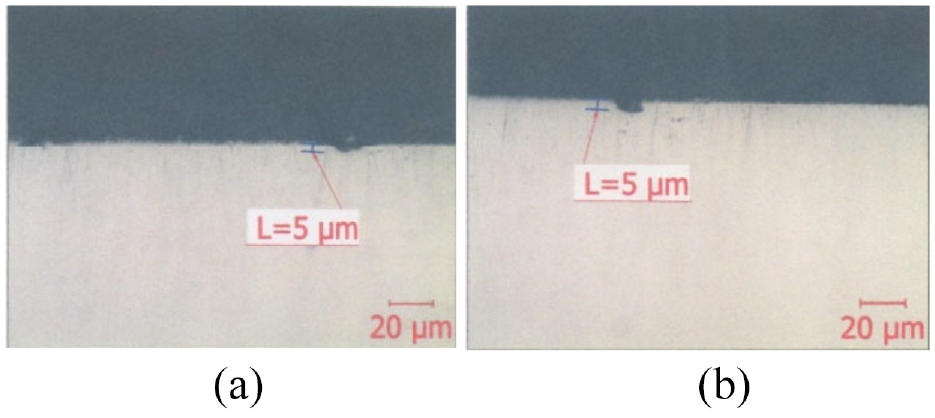
The depth of holes from the flaking of cemented specimens: (a) roller 6C and (b) roller 10C.

The depth of holes from the flaking of nitrided specimens: (a, b) roller к 1A and (c) roller 5A.
Conclusions
Analysis of the results of accelerated tests and subsequent studies of specimens confirm the legality of approaches to conducting such tests. This analysis shows that at specific contact load σ = 1140 MPa on the working surfaces of all tested samples initial foci of fatigue flaking wear were formed.
The acoustic emission method proved the high efficiency of recording the moment of transition of tribosystems from normal wear to initial fatigue failure. The proposed method of accelerated assessment of fatigue strength indicators of structural materials with the application of AE significantly reduces the time of expert evaluation. It can be applied for the development of new structural materials and ways to strengthen them.
The number of cycles before the initial foci of fatigue flaking wear on the specimens’ friction surfaces studied after fatigue strength tests are:
The bear specimen, strengthened by nitride treatment with a depth of nitriding 0.2 mm, worked out 97,500 cycles. The bear specimen, reinforced with gas cementation treatment with 1.2 mm depth, worked 47,000 cycles.
On average for four tests, pairs of specimens were worked out before the formation of the initial foci of fatigue notch wear:
- strengthened by nitriding treatment – 97,875 cycles.
- strengthened by gas cementation treatment – 53,812 cycles.
3. The working surfaces of the inhibited bear samples have more intense damages than the driving samples.
Integrated multi-cycle resistance to fatigue wear (destruction) of specimens strengthened by nitride treatment7–9 is more than 10 times higher than of cemented specimens. This is due to the mechanisms of fatigue destruction of cemented specimens (jaggs overlying the defect boundary).
The obtained results can serve as the basis for research on the application of ion-plasma technologies of nitriding instead of cementing to increase the contact strength of the surface of the parts, considering the advantages of this technology, such as maintaining the dimensions and high purity of contact surface treatment. Because of which there is no need for their mechanical completion after strengthening.
Comprehensive metallographic research conducted after accelerated tests and after long-term tests with high reliability confirm the fatigue nature of the destruction process that is recorded on the friction surfaces during their work. This confirms the workability and high reliability of the results obtained with the application the developed accelerated methodology for assessing the fatigue strength of structural materials. Using the proposed specific energy parameter of dissipation for one load cycle
Footnotes
Handling Editor: Chenhui Liang
Declaration of conflicting interests
The author(s) declared no potential conflicts of interest with respect to the research, authorship, and/or publication of this article.
Funding
The author(s) received no financial support for the research, authorship, and/or publication of this article.
References
 ;
;