
Abstract
Submarine pipeline is an important part of deep-sea and ultra-deep-sea oil and gas development. In the cold forming process of longitudinal submerged arc welded (LSAW) pipe, the JCO manufacturing process is one of the key forming technologies for manufacturing submarine pipeline. The main problem encountered by submarine pipelines in offshore oil and gas transportation is insufficient pipeline collapse pressure, which leads to pipeline collapse and shortens the service life of the pipeline. Therefore, the analysis of the JCO manufacturing process is of great significance to improve the collapse resistance of pipelines. In this paper, the development and research status of the JCOE/JCOC manufacturing process are reviewed. The stress, contact, and deformation of the plate are symmetrical in the JCOE/JCOC manufacturing process. The effects of expanding and compression on pipe collapse performance in the JCO manufacturing process are summarized. The asymmetric factors can reduce the collapse performance of the pipeline. Compared with expanding, compression can effectively reduce the ovality of pipe and strengthen the compression performance of pipe, to improve the collapse performance of pipe; finally, the JCOE/JCOC manufacturing process and collapse resistance of submarine pipeline is summarized and prospected.
Introduction
Marine oil and gas reserves are rich, accounting for about 1/3 of the total global oil and gas resources. The ocean has become the main field of global oil and gas production growth and exploration and development investment. With the breakthrough improvement of offshore oil exploration technology and equipment capacity, 50% of the major oil and gas exploration discoveries obtained in the world come from the ocean, mainly in deep water. 1 At present, offshore oil and gas development is gradually developing to the deep-water and ultra-deep-water fields more than 500 m. The depth of oil and gas development is increasing. Oil and gas transportation in deep-water has become an urgent problem to be solved. Pipeline transportation is favored by countries all over the world as a transportation mode with less one-time investment cost, low transportation cost, and higher safety factors. 2 Submarine oil and gas pipeline is an important way to connect the internal facilities of offshore oil and gas fields and export oil and gas resources. It is one of the indispensable key projects for the development of offshore oil and gas. It is known as the “lifeline of offshore oil and gas fields.” 3
Compared with land pipelines, submarine pipelines not only bear internal and external pressure, but also are subject to the combined action of various load environments such as submarine current, sediment, low temperature, and corrosive medium. Therefore, steel pipes applied to submarine pipelines will have higher requirements in terms of composition, performance, and size control. Submarine pipelines are usually butt jointed with seamless pipes or welded pipes as the main pipe. Welded pipes are applied to submarine pipeline construction with their excellent material properties, large-diameter pipe making capacity, high dimensional accuracy, and good delivery modes perceived by users, and highlight certain advantages in their construction. 4 The submarine pipeline is made of 40–60 feet (12.2–18.3 m) long steel plate by cold forming. 5 The forming processes mainly include UOE forming, JCOE forming, RBE forming, PFE forming, CFE forming, etc. The UOE process and JCOE process are most widely used, as shown in Figure 1.

Schematic illustration of the most important steps in the manufacture of LSAW pipes.
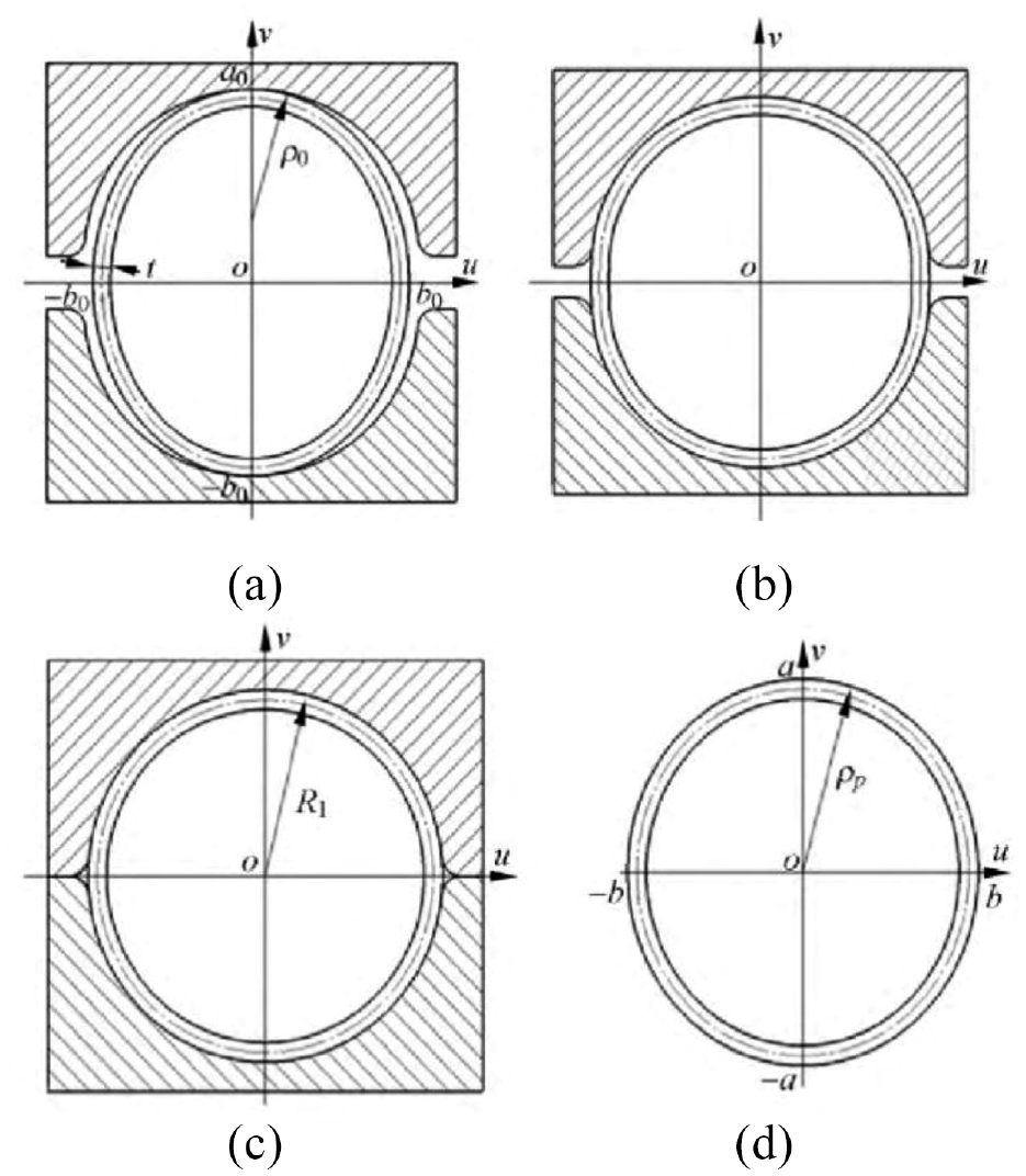
JCO forming process is a progressive molding process for the large-diameter pipeline, which has the advantages of low equipment cost and high applicability of pipe diameter.6,7 JCO forming means that the steel plate is bent into a cylinder after four steps, as shown in Figure 1. First, the edge of the steel plate is pre-bent into an arc shape as shown in Figures 2(a) and 3(a). One side of the steel plate is stamped on the stamping equipment in multiple steps to form a “J” shaped plate, as shown in Figures 2(b) and 3(b). The other side of the steel plate is bent in the same way to form a “C” shape, as shown in Figures 2(c) and 3(c). The middle part of the steel plate is pressed down to form an “O” shape of the opening, as shown in Figures 2(d) and 3(d). The stress, contact, and deformation of the plate are symmetrical in the JCOE/JCOC manufacturing process. Open welded pipe is welded by submerged arc welding. Welding thermal stress is asymmetrically distributed, so ovality defect is inevitable. Finally, the welded pipe with mechanical expanding (as shown in Figures 2(e) and 3(e)) or compression (as shown in Figures 2(f) and 3(f)) is used as an important means for final sizing and improving its ovality. 8 Expanding and compression can obviously improve the ovality of the pipe, the shape accuracy of the pipe, eliminate the residual stress of pipe forming, and make the pipe meet the required size requirements. The reduction of expansion or compression is usually 0.8%–1.0% of the pipe diameter.
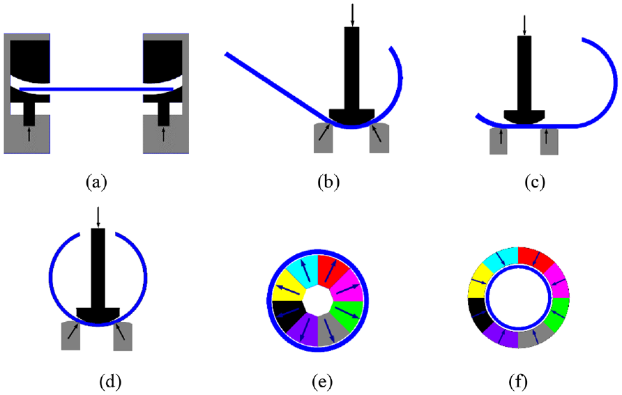
Schematic diagram of JCOE/JCOC forming process: (a) pre-bending, (b) “J” forming, (c) “C” forming, (d) “O” forming, (e) expansion, and (f) compression.
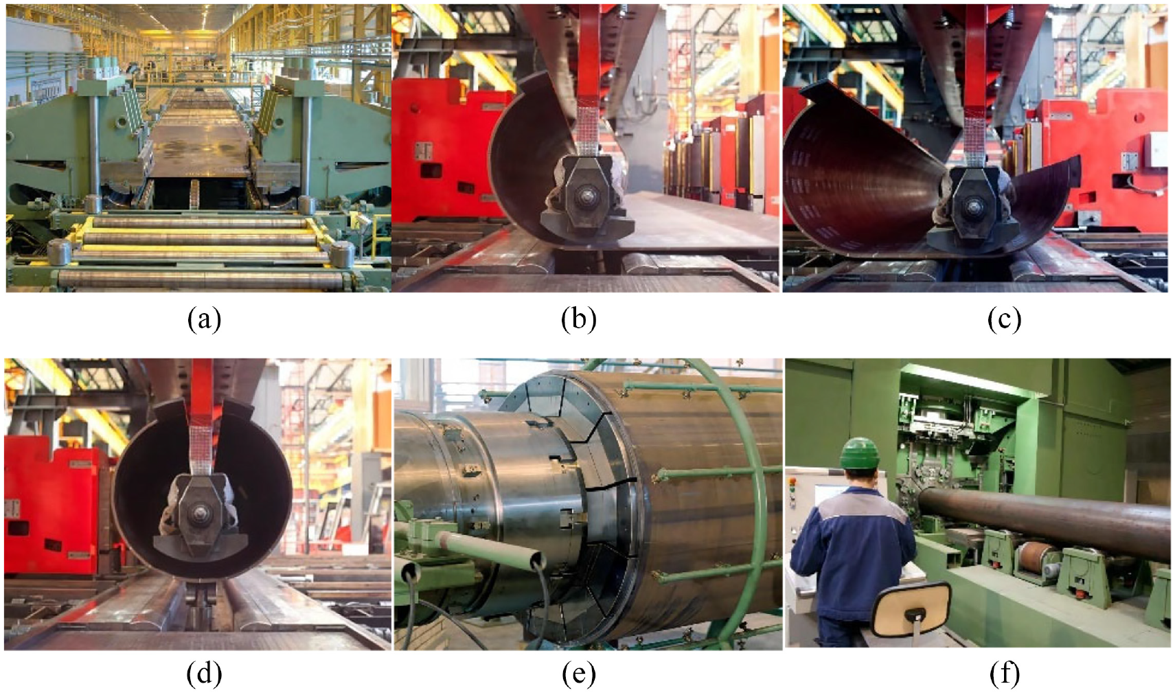
JCOE/JCOC forming site: (a) pre-bending, (b) ‘J” forming, (c) “C” forming, (d) “O” forming, (e) expansion, and (f) compression.
In this paper, the development and research status of the JCO manufacturing process are reviewed; the effects of expanding and compression on pipe collapse performance in the JCO manufacturing process are summarized, and the research on welded pipe compression is analyzed. The results show that compared with expanding, compression can effectively reduce the ovality of pipe and strengthen the compression performance of pipe, to improve the collapse performance of pipe; finally, the JCOE/JCOC manufacturing process and collapse resistance of submarine pipeline is summarized and prospected.
JCO manufacturing process
Pre-bending
Pre-bending is the first forming process in JCO forming process for LSAW pipe. The purpose is to make the curvature radius of the plate edge equal to or close to the nominal radius of the pipe produced by bending and deformation on both sides of the plate. If the plate edge is not pre-bent, forming defects such as outer pout and inner pout will appear after JCO forming, as shown in Figure 4. The pre-bending process is divided into roll pre-bending and die pressing pre-bending. Roll pre-bending is generally used for thin plates, and the forming quality of pre-bending is generally relatively poor. Die pressing pre-bending can be used for thick plates. 9 In the JCOE forming process of LSAW pipe, the die pressing pre-bending technology with involute shape is generally used for plate edge pre-bending.

Schematic diagram of pre-bending defects: (a) outer pout and (b) inner pout.
Gandhi et al. 10 built a mathematical model of forming force of pre-bending in the three-roller bending process. It can be used for capacity assessment and analysis of roller bending machines. Considering the effects of the various process parameters, Zhang et al. 11 developed a theoretical model of pre-bending, and identified the influence of roller radius, relative curvature, and arc length on the springback angle on the relationship between the springback ratio and the edge pre-bending angle. Qu et al. 12 established the elastic-plastic theoretical analytical model of pre-bending forming, obtained the mathematical expression between the bending angle and process parameters after pre-bending springback, as shown in equation (1), and carried out numerical calculation and verification. Gao 13 simulated the pre-bending process, and obtained the stress-strain distribution in the process and the relationship between the pre-bending shape and die loading, as shown in Figure 5.

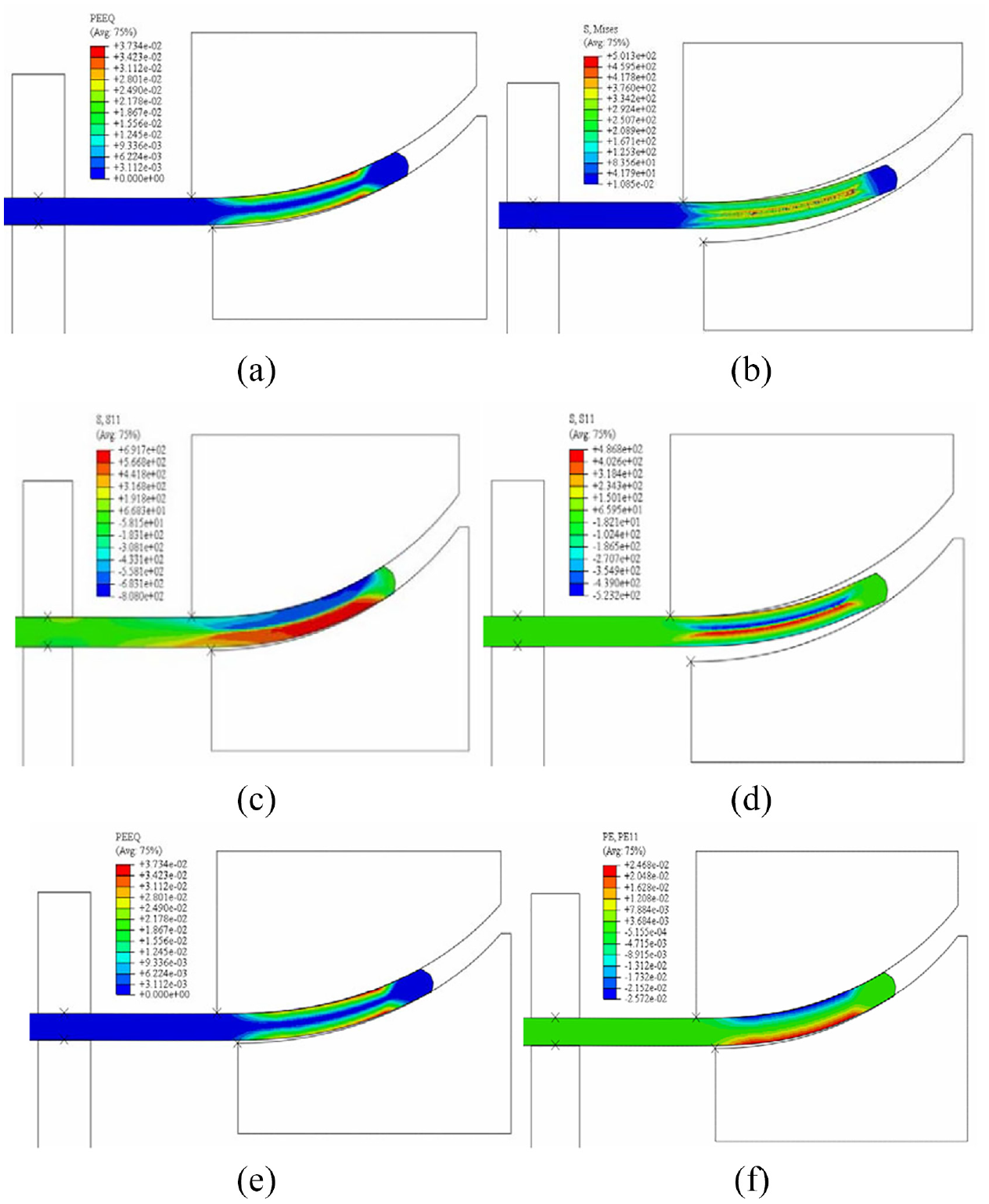
Schematic diagram of the pre-bending process with mold: (a) equivalent stress during loading, (b) residual stress, (c) tangential stress during loading, (d) tangential stress after unloading, (e) equivalent plastic strain, and (f) tangential plastic strain. 13
JCO forming
Because the JCO forming process is a progressive multi-step process, the plate has local geometric deviation, springback, and residual stress after each step bending; gradually the multiple cumulative errors of the whole pipe becomes larger and larger with the progress of forming. The cumulative error cannot be eliminated by mechanical expansion/compression, which will eventually affect the collapse performance of the pipeline. Therefore, it is very necessary to predict and compensate the springback, reduce the geometric deviation and eliminate the residual stress to improve the overall quality of the pipe.
Gao et al. 14 carried out the physical modeling and simulation study on the wide-plate air bending and obtained the regression equation used to predict the target bending angle. The numerical model of the JCO forming process was built to predict the final geometry of the pipe after forming for X-80 pipe with a wall thickness of 22 mm and diameter of 1219 mm, as shown in Figure 6, and the optimum punch displacement is found. Geometry comparison of simulating result and actual production is shown in Figure 7. 15

JCO forming process by FEM: (a) “J” forming, (b) “C” forming, (c) “C” forming, and (d) after “O” forming. 15

Geometry comparison of simulating result and actual production. 15
JCO process is a wide sheet metal air bending process. Its accurate springback prediction is important to improve pipe quality. Considering the geometric dimensions, material properties, process parameters, and friction conditions, Li et al. 16 established the theoretical model of free bending springback of the wide metal plates. The results calculated fit well with experimental data. Although there are some errors between theoretical analysis and experiment, the relationship between various factors and forming quality can still be obtained, which can be used as a reference for the macro evaluation of forming process. 17
When the punch is not covered by the sheet metal, the springback formula is as follows.

Where,
And when the punch is covered by the sheet metal, the springback formula is as follows.

Where,
Zhao et al. 18 proposed an intelligent control technology for forming steel pipe with JCO process based on plastic bending theory and machine vision technology, the principle of the intelligent control system is shown in Figure 8. The industrial application of precise bending is shown in Figure 9. The experimental results showed that the ovality of the formed pipes was less than 1.5% and the high-quality pipes can be manufactured without the worker’s operating experience by employing intelligent control technology. Intelligent forming of large diameter longitudinal welded pipe belongs to the development direction of pipe manufacturing in the future, which will greatly improve the quality and efficiency of pipe forming.

Principle of the intelligent control system for forming steel pipe with JCO process. 18
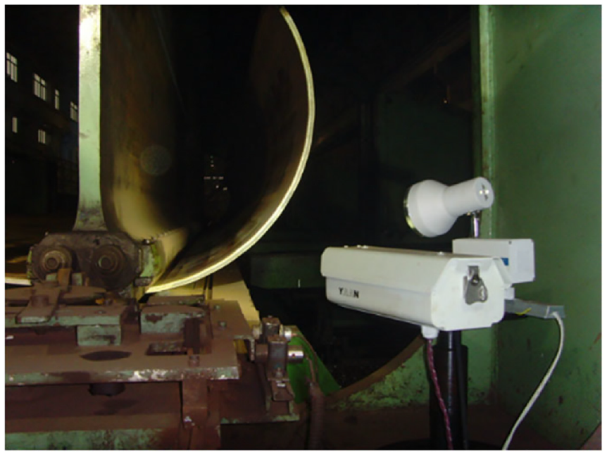
Industrial application of precise bending for forming the unfinished pipe with the JCO process. 18
Thome et al. 19 proposed a new solution for the process plan by closed-loop control of the JCO pipe forming, which enables the open pipes with a diameter range from 457 to 1422 mm, wall thicknesses of up to 45 mm, and 12.2 or 18.3 m long. Based on the computation model, the software system Shape was developed, including the three modules ShapeBase, ShapeView, and ShapeControl, as shown in Figure 10. The ShapeBase module is a semi-analytical process model, which is used for all forming calculations and optimization and calculates the process parameters. The ShapeView module is used to measure the pipe contour during the JCO process. The data of the pipe contour are instantly calculated in the ShapeControl module and checked. It realized real-time detection of deviations which are then converted into the next step and forwarded to the machine control. 20

Interaction of the Shape modules for process control. 19
Pipeline manufacturers have adopted three-point bending to produce large longitudinal welded pipes for a long time. Some scholars have made new explorations. Based on the mechanical principle of four-point bending as well as theoretical and experimental research on compression to adjust roundness, Zhao et al. 21 proposed a new technology called the four-point bending JCOC process. The schematic diagram of the four-point air bending JCO forming process is shown in Figure 11. The advantages of the new technology include fewer steps to the formation, higher productivity, dispensing with crimping process, less residual stress, higher flexibility, better forming quality, and preventing the expansion of flaws. Zhang et al. 22 established the mechanical model of the four-point bending JCOC process by analyzing the static equilibrium conditions and elastic–plastic deformation, simulated the process to find the maximum punch spacing, and further determined the formulation principles of other process parameters. In addition, a contour detection method for the LSAW pipes in forming process is proposed based on machine vision. The result shows that the error between the contour detection method and the coordinate measuring machine is less than 0.5%, and the roundness of pipes is less than 1.1%.

The schematic diagram of the four-point air bending JCO forming process. 22
Calibration methods
After JCO forming and welding, the section of the pipe cannot be an ideal circle. Ovality is an important technical index to measure the quality of the pipe. The ovality of pipeline plays a very important role in the collapse performance of the pipeline. Therefore, the ovality of the pipeline is strictly controlled. The current pipeline standard API (American Petroleum Institute) Spec 5L 23 stipulates that the roundness of pipe should not exceed 1.5% of the diameter (0.75% when the pipe is used offshore). To effectively reduce the ovality of the pipeline, the pipe calibration methods mainly include expanding process,24–30 compression process,25,31–35 over-bending setting round by mold press type method, 36 internal expansion over bending and calibration (IEOBC) process, 37 the symmetrical three-roller setting round process,38–40 the process of continuous and synchronous calibration of roundness and straightness by three rollers,41–46 and so on. Zhai et al. 37 built the intelligent control system of IEOBC process, which is mainly used for pipe end rounding . Yu et al. 38 proposed the symmetrical three-roller setting round process, built the mechanical model and numerical simulation model, 39 and carried out theoretical analysis and experimental research on process parameters. 40 Huang et al. 41 developed the symmetrical three-roller setting round process, which applies to thin-walled pipe, studied the process parameters, roller design, 42 mechanical model, 43 stress strain distribution, 44 deformation mechanism, 45 and weld influence. 46 At present, expanding and compression processes are mainly used to calibrate pipes in the industry.
Expanding process
The expanding process is one of the important processes in the LSAW pipe forming process. Expanding can improve the shape accuracy of the pipe, improve the pipe strength, and eliminate the residual stress of pipe forming. The pipe is usually expanded to 0.8%–1.5% of the radius of the pipe. The expanding process is shown in Figure 12, which consists of the initial state, deformation in elastic static, expanding, and springback.

The expanding process: (a) initial state, (b) deformation in elastic static, (c) expanding, and (d) springback. 24
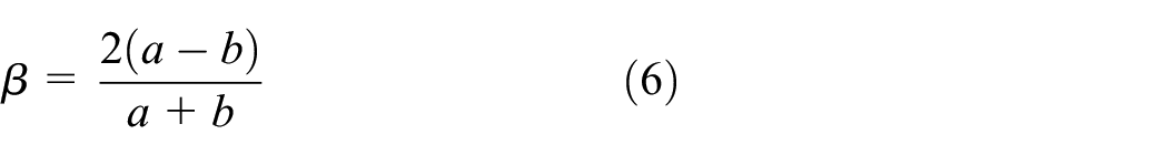
Scholars have done a lot of theoretical, numerical simulation, and Experimental Research on the expanding process. Herynk et al. 25 numerically simulated the expanding process in the UOE forming process with eight expansion mandrels, as shown in Figure 13. The effect of expanding on pipe forming is studied. Based on some basic hypotheses, Zhao et al.24,26 developed the small curvature plane bending theory, and then the curvature radius after the expanding process is expressed by equation (3), and the ovality after the expanding process can be calculated respectively by equations (4) to (6). The above theoretical results guide the practice of expansion engineering in the LSAW pipe manufacture.

Where,


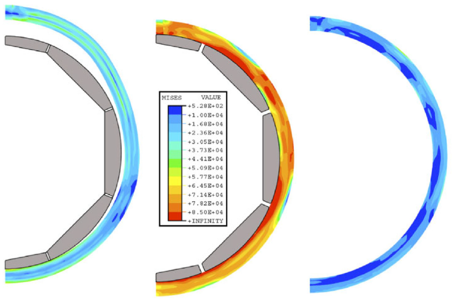
Three configurations during the Expansion process (von Mises stress shown in color contour). 25
Karrech et al. 27 developed a mathematical model to predict the stress field in the expanded zone of tubes under tension. The optimum mandrel angle ranges between 22° and 25°. For the mechanical expansion process of the large diameter pipeline, He et al. 28 analyzed the factors affecting the final product quality, and proposed the orthogonal optimization method. The optimal combination of process parameters is more conducive to improve the size and shape accuracy of products. Fan et al.29,30 used the finite element method to analyze the geometric parameters and deformation characteristics in the process of mechanical expansion. The research results provide a basis for improving the quality of the welded pipe. The JCOE forming process is implemented based on the MARC software. When the relative expander die radius is 1.05, the deformation of the pipe is uniform and the larger of the expanding ratio, the lower the residual stress when the expanding ratio is in the range 0.8–1.7. 47 .
Compression process
Although the expanding process has many advantages, it also has many disadvantages, such as high cost and complex structure of expanding equipment, which is prone to piston rod fracture. While compared with expanding, compression has more advantages. The die and equipment required for the compression process are much simpler than that of the mechanical expansion process. If the compression process can achieve the same sizing effect as that of the mechanical expansion process, the production cost of LSAW pipes can be reduced.
Herynk et al. 25 numerically simulated the compression process in the UOC forming process with 12 compression mandrels, as shown in Figure 14. The influence of process parameters on ovality and yield strength are discussed. Zhao et al. 31 studied a compression process with two half dies instead of the mechanical expansion process, as shown in Figure 15. The small curvature plane bending theory of curved beam was used to analyze the compression process. The springback equation of compression is expressed by the relationship between curvature radius of any cross-section after springback and initial geometric parameters, material properties, compression rate of pipe, whose form is similar to equations (2) to (5). In practice, the technical requirements for ovality generally are 0.5%–1%, and ovality after compression experiment is less than 0.12%, fully met the technical requirements. The relative deviation of theoretical and experimental results is less than 0.09%. Jun et al. 32 investigated and compared the mechanical properties and residual stress distribution in API-X70 pipes sized by expansion and compression processes with different sizing ratios. And from the aspects of mechanics, economy, and environment, the compression process is better than the expansion process.

Three configurations during the compression process. 25
Compression process with two half dies: (a) initial state, (b) setting round, (c) compression, and (d) unload. 31
With the improvement of steel plate quality and the increase of pipe wall thickness, and to ensure the accuracy of on-site track welding, the pipe size accuracy is further increased; the traditional pipe calibration becomes more difficult. To meet the new requirements of the pipeline market, Eisenbau-Kräme Company has developed a calibration technology for large-diameter longitudinal welded pipe, named Impander technology, and the press is called Impander® (EBK Brochure). Impansion is achieved using four compression tools as shown in Figure 16. Compared with the traditional calibration method, the difference of the new Impander technology is that four molds are used to work together, as shown in Figure 17. It is used to produce a pipe, which is rounder, has reduced residual stresses, and increased compressive yield strength. The calibration and compression produce pipes with internal diameter tolerances of less than 0.5 mm and ovality smaller than 0.3% over the whole length of pipe. A unique feature is that the compression tends to increase the compressive yield strength of the pipe. The combined effect of these features is a significant increase in the collapse pressure of the pipe.3,33,34 Peng et al. 35 proposed a two-roller continuous calibration (TRCC) process by compression, as shown in Figure 18. A springback analysis of compress bending is carried out, and an analytical model is established, which predicts ovality after calibration. When the reduction ratio is about 1%, the ovality is optimal. The ovality after calibration by theoretical analysis is about 0.03%, and the ovality after calibration by numerical simulation and experiment is less than 0.45%.

Impander principle. 33

Comparison of calibration methods with two dies and new calibration method with 4 dies: (a) traditional calibration method and (b) new calibration method. 33
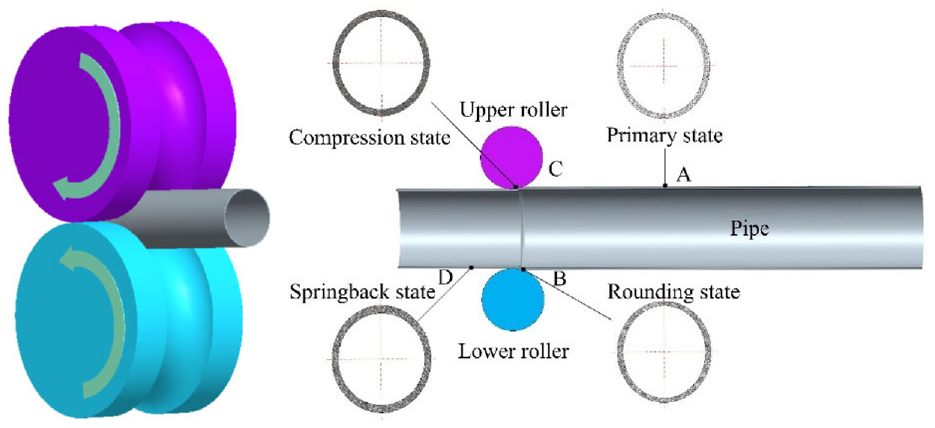
TRCC process. 35
At present, the research on compression is less than that on expanding in terms of pipe forming, many problems of the compression process still need to be deeply studied and verified, such as accuracy, participating stress, crushing performance, and so on.
Collapse resistance
Local buckling collapse and buckling propagation are the primary structural failure modes of submarine pipelines under high water pressure environmental loads, so pipes with high roundness are needed to meet the requirements.1,2 Relevant studies show that the collapse performance is related to the pipe forming process, weld quality and structure, ovality, heat treatment process, sizing method, pipe geometry, and so on. In the JCO forming process, the deformation of the pipe is ideally symmetrical. However, due to the non-uniformity of materials or improper control of process parameters, it will become asymmetric. The thermal stress or load received by the pipe during welding and sizing is also asymmetric, resulting in uneven residual stress. The above asymmetric factors will reduce the collapse performance of the pipeline. Janet et al. 48 proposed the statistical modeling approach to estimate the extrapolated collapse pressures of interest and assess sensitivity of these results to a range of features. Considering the shear deformation and thickness stretching of large deformation, a modified numerical calculation method based on the thick shell theory is established to determine the collapse pressure of thick-walled pipes. Verification experiments are conducted on 10 pipe specimens in hyperbaric chambers. 49 An analytical approach using finite element method is proposed to simulate the roll-forming, sizing processes, and collapse performance in manufacturing of ERW pipe made of API 5L X70 steel. 50
UOE pipeline can produce the pipeline with high roundness, and its ovality can be controlled at 0.15%–0.35%. Although its ovality is low, its collapse ability is weaker than that of seamless pipes of the same steel grade. 25 For the same geometry and material properties of steel pipe, its collapse resistance is reduced by more than 30%. The reason is caused by the cold forming process of the manufacturing process, especially the expanding process. 3 The expanding process increases the circumferential yield stress of the pipeline, while the yield stress decreases during compression due to the influence of the Bauschinger effect. 51 Kyriakids et al.52,53 developed a prediction tool to predict the collapse pressure of the pipeline. The model shows that the initial ovality will greatly affect the collapse capacity, while the change of wall thickness has little effect on the collapse capacity, and the residual stress has little effect on the pipe with lower D/t. If the axial yield stress is less than the circumferential yield stress instead of the axial yield stress being greater than the circumferential yield stress, the decline of collapse resistance can be avoided. When the pipeline is compressed to a sufficiently high strain, the collapse resistance will be further increased. When the reduction is about 1.0% of the normal diameter, the collapse pressure of the pipeline can be increased. Fryer et al. 54 confirmed the above conclusion through the full-scale failure test of compressed pipeline. Herynk et al. 25 research show that the compression process can improve the defects of small cracks and holes and improve the mechanical properties of welded pipe. The welded pipe after compression is under a higher bearing capacity than that after expansion. Numerical analysis is conducted on the effects of manufacturing process on the overall pipe behavior against pressure. The numerical results show that increase of expansion hoop strain leads to minimization of pipe out-of-roundness and, up to a certain limit value of expansion, it is beneficial for the ultimate pressure capacity of the pipe. Beyond this limit value of expansion, the collapse pressure resistance of the pipe is reduced. 55
Reichel et al. 3 proved that compression technology can significantly improve the collapse resistance of the pipeline through full-scale collapse experiments. It is proved that the ovality of the pipe is improved, the main reason is the result of the strengthening of the material under compression. The pipe after compression can not only improve the insufficient collapse pressure brought by the JCOE process, but also bring significant improvement. Compared with expanding, the pipe after compression can improve the collapse ability by 45%. The collapse picture of the pipe with compression is shown in Figure 19. Krishnan et al. 56 carried out a rigorous numerical simulation and test program to study the failure resistance of compressed steel pipe under the combined load of external pressure and bending, as shown in Figure 20, and established the collapse model under combined load. The comparison between the simulation results and the experimental results shows that the collapse pressure of steel pipe under the combined action of external pressure and bending can be increased by more than 35% by using compression instead of expanding. It is also verified that compression can effectively improve the collapse resistance of steel pipes.

Collapse picture of pipe with compression. 53

The failure resistance of compressed steel pipe under the combined load of external pressure and bending: (a) numerical simulation and (b) experimental steel pipe. 54
Heat treatment is one of the methods to improve the collapse ability of pipelines. Stark et al. 57 studied the influence of the cold forming manufacturing process on the collapse resistance of the pipeline. The test shows that the pipe without heat treatment is crushed between 36.3 and 46.0 MPa, while the pipe with heat treatment to eliminate residual stress is crushed between 58.13 and 60.96 MPa. The cold forming process will reduce the collapse resistance by more than 33%. Kathayat et al. 58 found that the cold formed steel pipe can recover the compressive yield stress of the pipe and obtain higher collapse pressure by heating to about 200°C–250°C and soaking for 2.5–3 minutes. The benefits of heat treatment are obvious, but the cost of eliminating residual stress is very expensive, and heat treatment will hurt the weld and corrosion resistance of the pipe.
Conclusions
The development and research status of the JCOE/JCOC manufacturing process are reviewed; the effects of expanding and compression on pipe collapse performance in the JCO manufacturing process are summarized, and the research on welded pipe compression is analyzed. Compared with expanding, compression can effectively reduce the ovality of pipe and strengthen the compression performance of pipe to improve the collapse performance of the pipe. How to get the minimum ovality to improve the collapse resistance of the pipeline is still a difficult problem and a research hotspot. At present, the research on the collapse performance of the JCO manufacturing process mainly focuses on the expanding process, but there is little research on the compression process to size the pipe.
JCOC manufacturing process has emerged in the fields of deep-sea oil and gas transportation, deep-sea structure construction, and so on. The multidirectional compression sizing process is a new method to realize “shape control” and “performance control” of the deep-sea longitudinal welded pipe. It breaks through the limitation of pipe diameter, pipe length, and wall thickness, improves production efficiency, and reduces the number of welds between subsea pipes; the weld quality and stress state of pipe is improved. The tensile residual stress in the forming process is replaced by compressive stress to improve the residual stress distribution in the pipe. However, some problems still need to be further studied on the multidirectional compression sizing process, such as the equipment development, die cavity structure design, theoretical model, and process parameter optimization and forming prediction. The in-depth study of the JCOC manufacturing process is of great significance to explore the development of efficient forming and high-quality deep-sea straight welded pipe, which will bring new development opportunities for deep-sea oil and gas development and pipeline construction.
Footnotes
Handling Editor: Chenhui Liang
Author contributions
Conceptualization, DP and BW; methodology, DP and BW; validation, JY, LH, JC, and HL; formal analysis, DP, BW, JY, and HL; investigation, DP; data curation, DP; writing – original draft preparation, DP; writing – review and editing, BW; visualization, DP; supervision, BW. All authors have read and agreed to the published version of the manuscript.
Declaration of conflicting interests
The author(s) declared no potential conflicts of interest with respect to the research, authorship, and/or publication of this article.
Funding
The author(s) disclosed receipt of the following financial support for the research, authorship, and/or publication of this article: This project was funded and supported by Special project for the construction of innovative provinces in Hunan (Grant Nos. 2020GK1021, 2019SK2271, 2019GK1010, 2019GK1012). Excellent Youth Fund Project of Education Department of Hunan Province (21B0471).