
Abstract
Offshore pipelines are exposed to potential submarine landslides. It is difficult to measure the impact forces exerted on a pipeline induced by submarine landslides because the upper seabed is very soft and an impact angle exists in practice. Current laboratory experiments are limited on measuring the normal force exerted on pipeline by the slides. This article describes the feasibility and performance of a novel penetrometer, which is designed to measure impact forces of submarine landslides on offshore pipeline including both the normal and frictional forces from variable impact angle in centrifuge test, termed as the lateral resistance measurement penetrometer. The calibration procedure for this particular version is illustrated in detail and the reliability and feasibility of the lateral resistance measurement penetrometer are preliminarily confirmed by an experimental study. Pipe–soil interaction centrifuge tests were subsequently performed on a normally consolidated kaolin sample with 40g level conducted in Dalian University of Technology drum centrifuge to investigate the effect of incident angles on the impact forces exerted by submarine landslides on a pipeline. The impact forces deduced from the lateral resistance measurement penetrometer are analysed in comparison with published results. The lateral resistance measurement penetrometer is a potentially valuable device to measure the interaction force between submarine landslides and offshore pipeline, cables and other subsea facilities in small-scale centrifuge models.
Introduction
Offshore pipelines that carry the hydrocarbon product to shore are exposed to impact risk by submarine landslides because of their length and varied terrain through which they must pass. Normally, pipeline only interacts with the upper ∼0.5 m of the soft seabed over very long linear distances, 1 and at these depths, the interaction forces between oblique submarine slides and pipeline are difficult to estimate. Critical issues are therefore what impact forces are exerted on a pipeline by submarine slides that is important for the design of pipeline. 2 The main emphasis of present studies is placed on the evaluation of impact forces from slide material with given rheological properties and moving at a given velocity. The general situation is indicated in Figure 1. 3 In the literature, studies of the effect of the incident impact angle on the resulting normal and axial (or frictional) tractions imposed on the pipeline have tended to be conducted with analytical solutions3–5 and numerical analysis4,6–8 while fall short in physical laboratory experiments. Flume tests 9 and centrifugal modelling tests10–13 were performed to investigate the impact force of submarine slides normal to the pipeline axis in which the axial forces were supposed to be negligible. The lack of experiment verification leads to failure in providing a comprehensive method to estimate the oblique submarine slides’ impact forces on pipelines. Therefore, in this article, a novel device is developed, which could measure the normal and axial forces acting on the pipeline model at the same time, named by the lateral resistance measurement penetrometer (LRMP) and also an experimental programme is designed and conducted.

Schematic representation of interaction between submarine landslide and pipeline. 3
The origin of LRMP is the vertically oriented penetrometer (VOP) which was designed to assess the shallow strength of soft seabed over continuous horizontal profiles, in which four pairs of strain gauges were mounted on a column for measuring the bending moments to infer the soil resistance. 14 The VOP is convenient to use for inferring the force magnitude and position of application, while it is not easy to determine the force orientation if an incident impact angle exists in practice. In this article, we develop a new device and propose that the LRMP can potentially be used as a means of determining the impact forces on offshore pipeline by submarine landslides. The process can be done by first vertically installing the LRMP with pipeline model mounted at the end to a specified total embedment depth, zt (measured from the mudline to the pipeline middle height) and subsequently dragging the LRMP horizontally along the mudline. In different tests, the pipeline models were mounted via an adjustable screw bolt at various angles with the direction in which the LRMP was travelling. During the process, the four pairs of LRMP strain gauges located at two perpendicular faces above the embedded cylinder portion will measure the bending moments generated due to soil resistance. The bending moments can then be used to infer the impact forces using the same concepts that are applied to assess the active slide-pipeline loadings in soft clay. 10 Compared to conventional penetrometers, the LRMP has the potential to measure soil resistance on the pipeline along continuous horizontal profiles and determine the accurate impact angle, as opposed to fixed direction measurement. The LRMP is simply to operate with low cost and is also easy to extend to infer the interaction forces between submarine landslides and other subsea facilities, like fixed platforms and cables by changing structure model at the end.
In this article, centrifuge validation tests with four types of pipeline models embedded at the depth of 2Dpipe in a normally consolidated (NC) kaolin sample are reported. All tests involved laterally dragging LRMP along the mudline at a constant horizontal translation velocity of 4.6 mm/s to assess the effect of incident impact angle on interaction forces. Impact forces derived from the LRMP are compared to those obtained from the existing model tests in which the incident impact angle equals to 90° to demonstrate the potential of the LRMP and validate the interpretation procedure. The effect of incident angles on the impact forces exerted by submarine landslides on a pipeline is also discussed.
Experimental apparatus
The LRMP
The LRMP, as shown in Figure 2, is a column made from 6061 T6-grade aluminium. For this particular version, the lower part is cylindrical with an outer diameter of 8 mm, as an embedded portion of ∼60 mm maximum. The upper part is square in cross section with a side length of 6 mm, and has a 120 mm length for providing a relative large plan where strain gauges can be glued in place. Four pairs of strain gauges, labelled a, b, c and d in Figure 2, are placed on two orthogonal faces and located at 110 and 165 mm, respectively, from the LRMP tip and remained above the soil surface. The metal foil strain gauges are coated with epoxy resin to avoid water ingress. During testing, the lower ungauged part of the LRMP with the model pipe mounted at the end is penetrated to a target depth within the soil and then translated horizontally. The top of the LRMP has a fixed connection to the actuator and the LRMP acts as a cantilever. The strain gauges provide a profile of bending moment above the soil, which can be used to infer the net horizontal force and its point of action as well as orientation.

Schematic representation of LRMP (unit: mm).
Dalian University of Technology drum centrifuge
A more straightforward approach for simulating the forces exerted by sliding materials’ impact on pipeline is to move a model pipe at a fixed velocity in a soil sample. Other test parameters such as the soil density and undrained shear strength can easily be varied by conducting test at different stages of consolidation. 10 The centrifuge testing programme described in this article was conducted in the Dalian University of Technology (DUT) drum centrifuge in a NC kaolin sample. At model scale, the channel containment area has a width of 370 mm (measured vertically) and a depth of 240 mm (measured radically). The DUT drum centrifuge has a full diameter (measured to the base of the channel) of 1.4 m and can rotate at up to 875 r/min. A complete description of DUT drum centrifuge and relevant hardware and software upgrades tailored for the high-velocity tests are described by Wang et al. 15
Model pipeline
Four model pipes used in the centrifuge tests have the same diameter Dpipe of 20 mm (0.8 m diameter in prototype) and were placed at different angles φ in the horizontal direction (i.e. the direction the LRMP was travelling), as shown in Figure 3. Both ends of the pipeline were cut into a horizontal plane and polished to eliminate the friction force exerted by slides’ flow. The results from the additional tests to study end effects are not presented in this article, in which end effects were proven to be negligible for those sizes of pipes. The forces within the flow width of 40 mm shown in Figure 3 were analysed during the simulation; thus, the length of each model pipe was decided.

Photograph of the model pipeline (unit: mm).
The practical use and interpretation for LRMP
The LRMP was first carefully calibrated prior to the application for model test. The top of the LRMP was tightly fixed to a steel square plate through which it was installed on the vertical load wall as a horizontally placed cantilever. The steel square plate was reinstalled at each step by rotating it clockwise at intervals of around
The four strain gauges form a full-bridge Wheatstone circuit, so the relationship between the responding coefficient of each strain gauge and the calibration load satisfies a sine function. For the first calibration load

The results from the calibration tests indicates the ratio of the responding coefficients of two strain gauges at the same position is not influenced by the application point when subjected to a fixed force, but the ratio will change with the variation of force direction and the relationship will satisfy a tangent function. In the subsequent analyses, the average of the ratios


Calibration data of resultant force angle equation.
which fits the measured results closely and is subsequently used to determine the incident loading angle associated with each pipe test. Also, it is observed that the
For practical application, the measured response of four strain gauges was recorded when the LRMP is subjected to the lateral loading. The voltage difference of each gauge from the initial value to the steady value was used together to calculate the ratio. It is possible to estimate the incident impact angle directly from

Then, the magnitude and application point of the impact force can be calculated together with the iteration method. First, a hypothetical application point is chosen adjacent to the suspension point in the calibration process. The corresponding coefficients of two strain gauges,
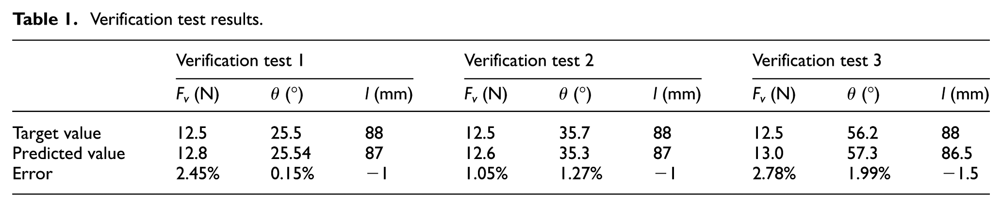
Verification tests were conducted to evaluate the feasibility and performance of the LRMP. A 12.5 N weight (Fv) was hung at the end of the LRMP located at a distance of 88 mm from the strain gauge as shown in Figure 2, and the force direction was changed by rotating the LRMP to be
Verification test results.
Sample preparation
The centrifuge tests were carried out using the UK kaolin clay which allows to conduct a series of tests with good sample consistencies and it was convenient to compare the test results with other centrifuge tests which used kaolin clay such as the work by Sahdi et al. 10 The kaolin clay has the mechanical properties described by Lu et al. 16 To prepare the sample, dry kaolin clay powder was first mixed with water at three times the liquid limit (155%) under vacuum in a customized clay mixer. The well-mixed slurry was then transferred to the whole drum channel while the centrifuge was spinning at an acceleration level of 40g (where the Earth’s gravitational acceleration, g = 9.81 m/s2) until primary consolidation was effectively completed. It took 3 days to make soil consolidate and the final clay sample was 125 mm decreased from the initial height of 280 mm which could be monitored by a digital camera fixed on the actuator. The settlement of the soil sample can be feasibly used to derive a rough scope of soil density, consolidation degree and soil strength through the empirical formula summarized by Lu et al., 16 in order to obtain a highly consistent, repeatable experimental condition available.
After the primary consolidation was completed, a T-bar with diameter of 5 mm and length of 20 mm17–19 was used to measure the shear strength of soil sample at a 0.2 s−1 strain rate. The shear strengths inferred from an initial T-bar penetrations

Pipe–soil interaction drum centrifuge test set-up.
Centrifuge testing procedure
The LRMP, together with the fixed model pipe, was attached rigidly to an actuator, which can be controlled by the software named EASI-V, capable of a maximum horizontal velocity of 0.157 rad/s relative to the drum channel (Figure 5) when the centrifuge was spinning at an acceleration level of 40g. All pipe–soil interaction tests were conducted by first embedding the pipe model vertically to the desired soil depth of 2Dpipe at a penetration rate of 1 mm/s and then dragging the LRMP along the mudline at a constant horizontal translation velocity of 4.6 mm/s. The measured response of four strain gauges was recorded during all the pipe model tests.
After completion of soil–pipe interaction tests, the LRMP without pipe model mounted will be immediately displacing horizontally at the same velocity and the same tip embedment, and the horizontal load from the LRMP itself will be subtracted from the measured load in the soil–pipe interaction test. As the interval time of these two types of tests is very short (less than 0.5 h), the soil sample is regarded as maintaining the same properties.
Test programme
An overview of the test programme is presented in Table 2. The programme involved four pipe tests and one additional so-called ‘shaft’ test. In the shaft test, only the LRMP itself was embedded at a depth equivalent to the shaft length exposed to the soil during pipe tests and translated laterally. The purpose of the shaft test was to measure independently the forces acting on the connecting shaft under the same conditions as the pipe tests, so the forces acting on the pipe can be isolated. To avoid potential boundary effects, all these tests were conducted at a minimum distance of 5Dpipe from the edge of drum channel. Also, a spacing of at least 4Dpipe was maintained between test sites to avoid the influences from previously formed footprints.
Test programme.

LRMP: lateral resistance measurement penetrometer.
Results of centrifuge tests
Resultant force
Figure 6 shows a typical example of the force–displacement and resultant force angle–displacement profiles. It is observed that force acting on pipeline model increases rapidly with the increase in horizontal displacement in the initial stage. The reason is that the moving velocity was relatively small, and the speed of actuator reached stability in a very short time. The force value shows a slight increase with the horizontal displacement increase from 0.2Dpipe to 1.5Dpipe. This should be caused by the soil around pipe model which was disturbed by the penetration of pipe model. The force due to the soil resistance became almost unchanged when the horizontal displacement exceeded a critical value in the later stage. For subsequent analyses, only the steady force and angle values are considered. These values are extracted, ignoring the initial build-up and decay of force and any initial peak in resistance.

Force value and angle–displacement profile for PS-3: (a) resultant force, (b) normal force, (c) axial force and (d) resultant force angle.
The action position of resultant force of pipe tests is approximately located at the middle line of pipe section with an error of ±2 mm. The reason is that the soil strength of the upper layer of the seabed was almost homogeneous within the scope of the pipe height, although the soil strength increased slightly with the increase in depth.
The centrifuge test results are more easily compared with other published results under normalized conditions. The normal force and axial force are normalized through


where NH is the normal coefficient, fa is the axial coefficient, FH is the measured normal force, Fa is the measured axial force, AH = Lpipe*Dpipe/sinφ is the normal force acting area, Aa = π*Dpipe*Lpipe/sinφ is the axial force acting area and su is the undrained strength of soil at 2Dpipe embedment depth. All pipe–soil interaction test results are listed in Table 3.
Results of centrifuge tests.
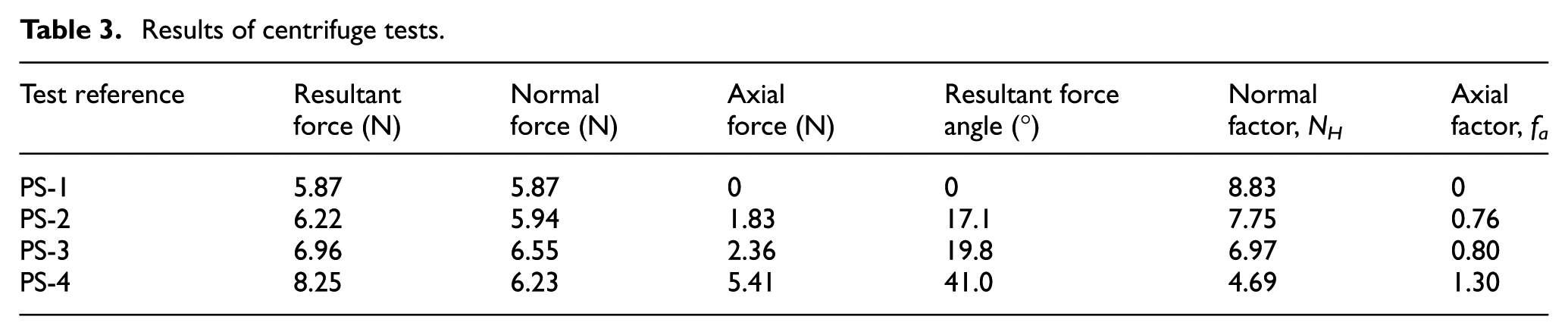
The normal factor, calculated by 90° test data, is 8.83, which is within the scope of 6–10 calculated through centrifuge data proposed by Sahdi. 20 However, the presented NH is lightly higher than the best fitting data 7.35 proposed by Sahdi. 20 It is may be due to the couple effect influenced by the longitudinal flow of slides along the pipe surface that will change the flow mechanics of slides against the pipe model. In addition, the axial force measured in this test is tiny, which can be ignored, meaning that the resultant force angle is 90°.
The resultant force angle, θ, measured in 30°, 45°, 60° and 90° tests is shown in Figure 7. In general, resultant force angle decreases with the increase in impact angle φ. It is observed that when the impact angle increases from 0° to 30°, the resultant force angle decreases from 90° to about 40° sharply. Then, the decreasing trend of resultant force angle slows down with the further increase in impact angle. This trend agrees well with the existing computational fluid dynamics (CFD) results, 8 which shows a faster decrease in resultant force angle at the range of 0° to 30° impact angle.
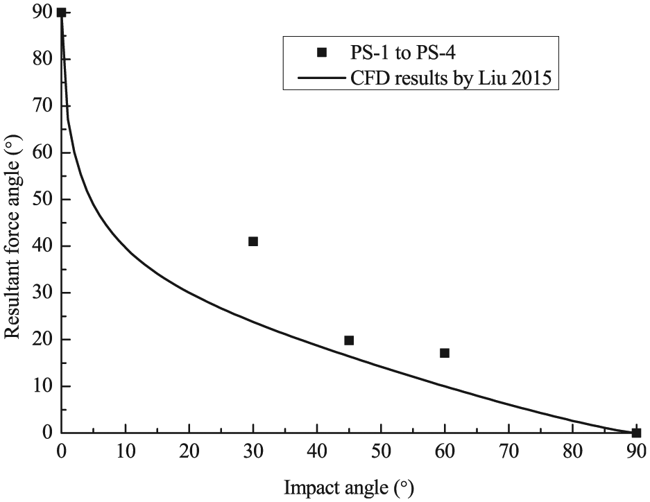
Resultant force angle versus impact angle.
The NH results of different impact angle tests are drawn in Figure 8. When the impact angle is 0°, the NH would be 0 in theory because the formal force acting on pipeline would not exist. Liu et al. 8 estimated impact forces induced by landslides on pipeline using a CFD approach, and the variation of normal factor NH with the flow angle relative to the pipeline axis is also drawn in Figure 8. Both centrifuge test results and CFD results show a similar changing tendency. So the same estimate equation form is adopted and the best fitting of centrifuge test data can be expressed as follows


Normal bearing capacity factor versus impact angle.
It is noted that the CFD data are bigger than centrifuge test data at the same impact angle. The reason is that in CFD calculation, the pipe is designed to be suspended and free from near-surface effects where a full-flow mechanism is expected to occur. In centrifuge tests, the pipe embedment is 2Dpipe (from the top of soil surface to the mid-height of pipe), which is may be not sufficient to establish a full-flow mechanism according to existing research results.10,21
Figure 9 shows the axial factor, fa, of different impact angles, φ, including CFD results by Zakeri 6 and Liu et al. 8 All these results show that the axial bearing capacity factor fa decreases with the increase in impact angle. The variation of fa and φ can be expressed as follows


Axial factor versus impact angle.
Equations (6) and (7) can be applied to assess the impact force acting on pipeline at 2Dpipe embedment condition. It should be noted that as the fa data seem a bit scattered, more tests are needed to modify these equations to give more reliable assessment.
Conclusion
The feasibility and performance of a novel device named LRMP are evaluated in this article, by means of both the conventional gravity test and centrifuge test in NC kaolin clay. In addition to being able to measure comparable net horizontal force and its associated moment arm with the conventional VOP device, the LRMP as an improved version can be used to determine the incident impact angle generated from the soil resistance when simulating the slides–pipe interaction. The oblique load deduced from the LRMP verification test exhibits good agreement with the target values. The limitation of this novel device is that the response of the LRMP is too sensitive when the inclined angle falls into the range of 140°–180°, which will be improved further. At this situation, the LRMP will have to be reinstalled appropriately at a different angle to repeat the model test to re-estimate the inclined angle for a better precision.
The effect of incident angles on the impact forces exerted by submarine landslides on a pipeline was investigated through a series of pipe–soil interaction centrifuge tests. Results show that the predicted normal bearing capacity factor and axial factor inferred from model tests have a similar tendency with the published numerical analysis results. The difference is maybe explained by the different measuring means for the soil strength or the different flow mechanics. But it is very possible that those two factors suggested in the literature are overestimated, and more tests need to be conducted in the future for providing a more reliable assessment.
This study only shows the usage of the LRMP as a novel device to measure the impact forces by slides on a pipeline; actually, it could be extended to measure the interaction force between submarine landslides and offshore pipeline, cables and other subsea facilities in small-scale centrifuge models by changing the models at the end of LRMP, which makes the LRMP potentially attractive for future use to evaluate the interaction forces and which is important for the design of offshore structures that interact with the shallow seabed.
Footnotes
Handling Editor: Lalit Borana
Declaration of conflicting interests
The author(s) declared no potential conflicts of interest with respect to the research, authorship, and/or publication of this article.
Funding
The author(s) disclosed receipt of the following financial support for the research, authorship, and/or publication of this article: This work was supported by National Nature Science Foundation of China under grant nos 41772296, 51639002 and 51778107.