
Abstract
Based on the configuration of the Stewart parallel mechanism (SPM), after analyzing the kinetostatic characteristic of a planar four-bar linkage with attached springs which works around the kinematic limb-singularity, a process of constructing a novel multi-degree of freedom (DOF) parallel passive compliant constant-force mechanism (CCFM) is presented. The kinematic limb-singularity of a rigid four-bar linkage with attached springs is obtained and then is applied to construct a constant-force compliant mechanism (CM) based on the pseudo-rigid-body-model by designing appropriate structure parameters to obtain appropriate equivalent spring stiffness of flexures. The CCFM is further used as the branches of the SPM and then a passive multi-DOF parallel mechanism (PM) is constructed. Here the method of replacing the original rigid branch of the PM with the CCFM is called the “Expanded Rigid-body Replacement Synthesis” (ERBRS). The multi-DOF parallel passive CCFM can generate a constant-force zone when makes a small pose transformation around a certain position, where each compliant branch is located at the constant-force zone. The proposed CCFM can be applied in practice such as the polishing machine which needs the constant contact-force between the polishing head and the workpiece. The proposed method of constructing a CCFM with one- or multi-degree of freedom mechanism has some important reference value on designing other types of CCFMs.
Keywords
Introduction
Constant-force mechanism (CFM) also called zero-stiffness mechanism generates nearly constant-force over a range of displacement. 1 The force can be kept invariable without precise sensors and additional actuators, which reduces the control effort and increases the reliability. A conventional method of constructing a CFM is to attach springs to the joints after assigning certain stiffness.2–4 The rigid-body CFMs with attached springs may have backlash, friction, and much difficulty in obtaining accurate springs stiffness and assembling links, which can be avoided by compliant CFM (CCFM). Therefore, generations of CCFM attract many authors’ attention, 5 as the CCFMs can be applied in many fields such as safe grasping operation 6 and precision polishing. 7
Generally, a constant-force output can be generated by adopting a set of high precision sensors and complex control algorithms,8,9 which may cost much. For reducing the complexity and cost, many researchers gradually are focus on the design of mechanical CFM.10,11 A CCFM can usually be constructed by combining the negative stiffness of a bi-stable buckling beam and the positive stiffness of a linear flexure.12,13 It is easy to comprehend the stiffness combination method with an obvious physical meaning, but the different structural forms by using this method are simple and similar to each other. Another familiar CCFMs design process is by optimizing the shape and structural parameters of different types of curved beams,14–17 which is difficult to be applied in practice as it is difficult to fabricate the complicated curved beams with considering the limitation or complexity of the mechanical processing. Furthermore, most of the CCFMs obtained by the two above-mentioned methods have only one-degree of freedom (DOF), which are also limited in application fields such as multi-DOF constant-force polishing machine.18,19 The common compliant mechanism (CM) design approaches including Motion or Constraint Synthesis,20–22 Freedom and Constraint Topology (FACT) 23 and Topological Synthesis 24 have difficulty in directly obtaining the multi-DOF CCFMs.
At present, the Pseudo-Rigid-Body-Model (PRBM) are widely applied in analysis and synthesis of CMs, 25 but it needs the designers to well comprehend the characteristics of the rigid-body mechanisms. Therefore, combining the PRBM and some common characteristics of the rigid-body mechanisms to construct the CCFMs has much important theoretical meaning and practical value. One-DOF CCFM can be constructed by using the kinematic singularity of the planar mechanism and the PRBM. 26 Furtherly, design of multi-DOF CCFM by combining the PRBM and the characteristic of parallel mechanism, which is applied in many fields such as motion simulator, parallel machining tool, 27 and lifting actuator on stereo parking robot,28,29 is a useful method of designing new types of multi-DOF CCFM. In this paper, a one-DOF CCFM is designed and then is used to as the branch of the multi-DOF CM originated from the Stewart parallel mechanism (SPM). The rest of this paper is organized as follows: in Section 2, explanation about the condition of the kinematic limb-singularity is given based on the position analysis. Section 3 establishes the kinetostatic model of the crank-slider linkage with attached springs and analyzes the influence of spring stiffness on the force-displacement curves. Section 4 explains the process of six-DOF spatial CCFM generation by using the planar CCFMs as the branches based on the PRBM. Finally, Section 5 presents discussion about the case that the CCFM is applied in practice followed by conclusions in Section 6.
Kinematic limb-singularity
The schematic of the crank-slider four-bar linkage is shown in Figure 1, where r1, r2 are the corresponding length of the link 1, link 2, respectively, and r3 denotes the distance between pin joint C and pin joint A. With the premise of r3 being greater than r2, that is, r3 ≥ r2, slider 3 moves along the horizontal line and drives link 1 to oscillate around point A where a rotation pair locates. Link 1 also called crank and the base denoted by 4 are connected by the rotation pair located at point A which is called pin joint A. Link 1, that is, the crank, and link 3, that is, the slider, are connected by link 2, that is, the connecting rod.

Schematic of the crank-slider four-bar linkage.
With the Cartesian coordinates frame being attached to the ground 4 at pin joint A, θA, θB, and θC, which define the relative rotational angles between the two adjacent moving links at the three pin joints can be calculated by directly using the position analysis or the cosine law as follows:


The initial three intersecting angles θA0, θB0, and θC0 can be written easily by writing r3 as r30, where r30 is the initial position of point C along x-axis, that is,


Supposing slider 3 being the input, the differentiation of the above angle, θA, with respect to the input variable, r3, can be obtained as follows:

If the following is satisfied,
we can easily obtain
The differentiation of other two angles θB and θC, with respect to the input variable, r3, can be obtained easily, which are not detailed here.
It indicates that when the input link 3 moves on the application of the driving force, Fd, if link 2 is perpendicular to x-axis, the mechanism locates at the kinematic limb-singularity position, where the input link 3 moves but the output link 1 is instantaneously motionless. Here we recommend the readers to Li and Hao 26 to get more information about the kinematic limb-singularity of a planar mechanism.
Force-displacement characteristics
As the planar crank-slider mechanism with springs is used to construct the CCFM, the variation of the applied force versus input displacement based on the kinetostatic model of the planar mechanism should be established. Then the stiffness characteristic of the planar mechanism can be analyzed and the CFM can be produced.
Kinetostatic model
We suppose that every pin joint of the mechanism is placed a torsional spring. After applying the external driving force on the input slider, the motion process of the mechanism being driven is shown in Figure 2, which depicts the mechanism moving from the nonsingular initial position through the kinematic limb-singularity position and then stops at the nonsingular end position. The variation of the driving force, Fd, versus input displacement, S, will exhibit nonlinear characteristic as the existence of the three torsional springs placed at pin joints A, B and C whose stiffness are denoted by KA, KB, and KC, respectively.

Motion of the crank-slider with springs. (a) initial position, (b) kinematic limb-singularity position, and (c) end position.
The potential energy of the mechanism moving as shown in Figure 2 can be written as

After substituting r3 = r30 − S and equations (1a) through (1c) into equation (2), based on the virtual work principle, 26 the external force, Fd, versus the input displacement, S, can be derived:

According to equation (3), the variation of external force versus input displacement, that is, Fd-S curve, can be depicted.
Zero-stiffness generation
It is evident that the external force varies with the position changing of the mechanism because the placed springs whose internal torque will change with the rotational angle variations of the three joints. In other words, the attached springs cause the external force to exhibit a nonlinear stiffness characteristic. Therefore, the influence of the spring stiffness on the force-displacement curve is the construction fundament of the CCFM and so should be investigated before zero-stiffness (constant-force) generation of the mechanism with attached springs.
When the geometry parameters of the mechanism are given as constant, the influence of the spring stiffness on the stiffness characteristic can be quantified as shown in Figure 3.

Nonlinear stiffness characteristic of the mechanism.
Figure 3 indicates that when the geometry parameters are given as r1 = 80, r30 = 81,and r2 = 32 mm and KA = 100, assignment of appropriate KB and KC makes the mechanism to produce corresponding stiffness characteristic, where the unit of the torsional spring is N.mm/°. With the increment of KB and KC, the stiffness characteristic exhibits from the bi-stable stiffness characteristic through the partial negative-stiffness to the positive-stiffness characteristic. One can conclude that by assigning appropriate spring stiffness the mechanism may produce a partial zero-stiffness zone where the external force can keep constant for a certain input displacement. Here an example of the zero-stiffness zone exists where KA = 100 N.mm/°, KB = KC = 0.24 N.mm/°. The zero-stiffness zone where Fd satisfies

is considered as the zero-stiffness region and marked within the two red short lines in Figure 3, where
One can see that on the given above mentioned geometry parameters, the torsional spring stiffness at joint A is much larger than the torsional spring stiffness at joint B and joint C.
Construction of the six-DOF CCFM
Section 3 presents that if the stiffness of the attached torsional springs are assigned as appropriate, the external force applied on the slider may exhibit the partial zero-stiffness characteristic, where the Fd-S curve possesses the constant-force zone. In this section, the four-bar linkage with attached springs is employed to construct the CCFM by using the PRBM, which is further used as the compliant branches of the 6-DOF CCFM.
Figure 4 gives a CM which is considered as composing of two crank-slider mechanisms by parallel connection, where Body 1 and Body 2 correspond the ground and the slider, respectively. Three beams placed at Ai, Bi, and Ci (i = 1, 2) resulting in the corresponding torsional spring stiffness can be estimated by the following equations. 30


The parallel connection of two compliant crank-slider mechanisms.
where E is the Young’s Modulus, I1, I2 are the corresponding second moment of area about z-axis. L1 is the length of the long beam corresponding to the link 1 rotated around Ai (i = 1, 2), and l2 is the length of the four beams located at Bi and Ci (i = 1, 2). For the geometry parameters corresponding to the PRBM mechanism, it should be noticed that the equivalent length of the link 1 of PRBM is about 0.86L1. 25 Furtherly, according to the PRBM the axes of the equivalent rotation pairs locate at the centers the two short beams. From the geometry, one can see that the distance between Bi and Ci is L2 − 2 × l2/2 = L2 − l2. It is more usual that designers can also firstly determine the geometry parameters and the torsional spring stiffness by employing equation (3) to obtain a PRBM mechanism with the desired zero-stiffness (constant-force) characteristic, and then simulate the Fd-S characteristic by using the finite element analysis (FEA) analysis. If the FEA results exhibit the partial negative-stiffness, one may decrease KA or increase KB by set appropriate structure parameters of beams according to equation (4). Otherwise the FEA results address that the mechanism exhibits the positive-stiffness characteristic, designer should set greater value of KA or less value of KB according to equation (4).
When the length and in-plane thickness of two short identical beams at Bi (i = 1, 2) is given as t2 = 0.2 mm, the in-plane thickness of two long identical beams at Ai (i = 1, 2) is given as t1 = 2.8 mm, and the other structure parameters are given as L1 = 94, L2 = 39, L3 = 93,and l2 = 8 mm, the Fd-S curve obtained by FEA and the curve result calculated by PRBM are described in Figure 5. Here the meanings of geometry parameters are as follows: L1 is length of the two long beams, L2 is the distance between the ends of the two short beams locating at Bi and Ci, L3 is the original distance between two ends of Body 1 and Body 2, l2 is the length of the two short beams locating at Bi and Ci, and t1, t2 are the in-plane thick of the long beams and the short beams, respectively. It can be seen that the results computed by FEA and PRBM are not coincident, but the CM generates zero-stiffness (constant-force) characteristic.

Comparison between FEA analysis and PRBM result.
The above obtained CCFM presents the constant-force characteristic when the Body 2 applied by an external horizontal force moves along the symmetric line as shown in Figure 4. In fact, according to the Grubler’s Criterion, 31 if the CM is three-DOF and Body 2 can also moves in other direction where the external force applies, the mechanism will not generate the zero-stiffness (constant-force) characteristic. Therefore, in order to make Body 2 to always move along the symmetric line, we place two compliant spherical pair at the left end of Body 1 and the right end of Body 2, respectively, as shown in Figure 6. Then even if the external force, Fd, offsets the symmetrical line a little, Body 2 would be certainly loaded and moved along the horizontal line. In other words, after adding two spherical compliant joints at the two ends of symmetrical line of the CM as shown in Figure 6, Body 2 will mainly moves along the symmetrical line. Thus the CM can be considered as being only one-DOF.

The CM with added two compliant spherical joints.
If the CCFM as obtained earlier is used to replace the translational pairs of a parallel mechanism (PM), whose other types of kinematic pairs are also replaced by corresponding simple complaint joint by using the “Rigid-body Replacement Synthesis (RBRS),” 20 the new type of obtained complaint PM which always works around a given position may exhibit passive constant-force characteristic. Here we call the method of replacing the simple original rigid-body pair with the same DOF complicated CM the “Expanded Rigid-body Replacement Synthesis (ERBRS).”
By taking the rigid-body SPM configuration whose configuration is presented in Appendix as the original mechanism and applying the ERBRS, after replacing each rigid-body sphere-prismatic-sphere (SPS) branch with the CM as shown in Figure 6, a novel multi-DOF CM as shown in Figure 7 is constructed. We can deduce that the external load, Fd, applying on the up moving platform may exhibit a constant-force zone after designing the appropriate structure parameters mainly including the thickness and length of flexures.

The multi-DOF CM based on the SPM and the ERBRS. (a) The schematic of the SPM and (b) the compliant PM.
For the sake of exploration, the fixed frame is attached to the fixed platform where Ni locates, which is shown in Appendix. The Z-direction distance between MiNi is 215 mm for the original assembly. Here the material of the mechanism is set as aluminum alloy 7075-T6 with the Young’s Modulus of 71 GPa and the Poisson’s ratio of 0.33. When the flexure parameters as shown in Figures 4 and 6 are set as L1 = 94, L2 = 39, L3 = 93, d = 5, r = 2.5, and t = 0.6 mm, and the geometry parameters of the PM are given as Rm = 125 mm, Rb = 130 mm, β m = 90°, and β b = 100°, where the definition of parameters Rm, Rb, βm, and βb are addressed in Appendix, the finite element analysis (FEA) is descried in Figure 8, where the fixed platform is not represented so as to calculate the each branch reaction force. It should be noticed that the different parts should be set as corresponding mesh sizes as they have different cross section dimensions. Here with tetrahedral mesh the details of the model are given as follows: mesh size of thin beams is set as 0.2 mm, mesh size of the flexible ball joint is given as 1 mm, mesh size of other parts is 1.5 mm and the number of the grid node is 688,205.
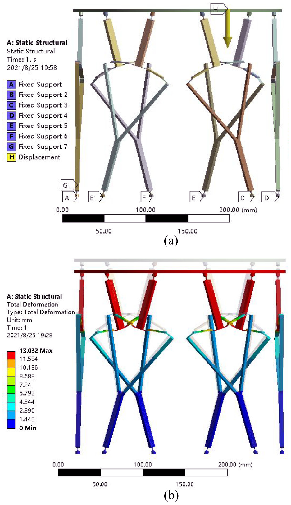
Finite analysis of the mechanism. (a) Constraint settings and (b) simulation of deformation.
Figure 9 presents the FEA result that indicates the Fd-SZ curve, where SZ is the displacement of the up moving platform along the negative Z-axis direction.

External force variation versus Z direction displacement.
From Figure 9, one can see that on the condition of afore given parameters, Fd-S curve has a constant-force zone around SZ = 9.0 mm. In order to verify the multi-DOF constant-force characteristic, here the moving platform is set to make a pose (position and orientation) transformation around SZ = 9.0 mm, that is, the position center of the six joints Ni (i = 1, 2, …, 6) with respect to the fixed frame O-XYZ is (0, 0, 215) mm as shown in Figure A in the Appendix.
Figure 10 further gives the reaction force variation of each branch versus the displacement of the up moving platform. It shows that when the moving platform moves in the negative Z-direction, each reaction force may keep constant when the moving platform works around the displacement of Sz = 9.0 mm in the negative Z-direction.

Reaction force on each branch when platform moves in Z direction.
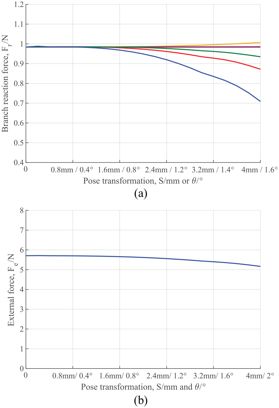
After moving to the negative Z-direction displacement of Sz = 9.0 mm, Figure 10 further describes the case that the moving platform translates in X-direction.
From Figure 11, we can see that each branch reaction force and the external force are constant within the given pose transformation.

The case of moving in X direction. (a) Branch reaction force variation and (b) external force variation.
When the moving platform firstly translates to the negative Z-direction displacement of Sz = 9.0 mm, and then makes a further pose transformation of 4 mm displacement in direction of vector (2; 0; 2) mm and simultaneously gradually rotates 2° about y-axis, Figure 11 shows that the variation of external force applied on the moving platform versus the further pose transformation, that is, translational displacement S or rotational angle θ.
Figure 11(a) shows that each branch reaction force keeps nearly constant for a certain zone when the displacement is less than 2.0 mm in direction of vector (2; 0; 2) and the rotation angle is less than 2° about y-axis.
From Figures 9 to 12, we can conclude that when the moving platform works around the pose where each branch force reaction keeps constant, the external force applied on the moving platform can also remain nearly constant. It indicates that the multi-DOF passive CCFM originated from the SPM by using PRBM and ERBRS can generate multi-DOF constant-force.
The case of moving in direction of vector (2; 0; 2) mm. (a) Branch reaction force variation and (b) external force variation.
Discussion
Section 4 presents that the value of the external force applied on the moving platform keeps nearly when each branch works around the position where each branch reaction keeps nearly constant. This characteristic has a wide range of applications. For example, when the SPM is employed in the polishing machining, which needs the contact force between the polishing head and the workpiece to keep constant as shown in Figure 13. Here each branch of the SPM is replaced by the compliant branch with constant-force characteristic and then the CCFM is obtained. When the moving platform passively makes a pose transformation because of the complex surface, if the CCFM originated from the SPM works around the pose where each compliant branch is located at the constant-force zone, the polishing head can keep constant polishing force applied on the surface of the workpiece. The passive constant-force polishing head greatly reduces the cost and improve the processing efficiency in comparison of using the complex control system to obtain a precise constant contact force.
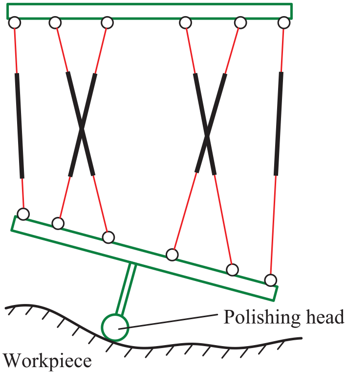
The CCFM being employed on polishing surface.
Conclusions
In this paper a feasible process for designing a novel multi-DOF passive CCFM is addressed. This work relies the well understanding of kinematic property of the one-DOF rigid-body mechanisms. By using the pseudo-rigid-body-model and assigning appropriate structure parameters to obtain corresponding equivalent stiffness, the one-DOF CCFM works around the kinematic limb-singularity is constructed. Based on the multi-DOF parallel mechanism, the “Expanded Rigid-body Replacement Synthesis” proposed in this paper is an effective method to construct a multi-DOF constant-force mechanism. It should be pointed out that the concentration of this paper is an evaluated process of designing a multi-DOF constant-force PM rather than obtaining an accurate mechanics model. The design process has much reference value in constructing a similar multi-DOF PM with constant-force applied on the workpiece. Our future work will focus on establishing an accurate mechanics model to obtain the desired value and range of the constant-force, which is followed by some experimental testing.
Footnotes
Appendix
The sketch of the SPM is shown in Figure A. The mechanism consists of a moving platform and a fixed platform connected via six identical SPS legs MiNi (i = 1, 2, …, 6), where S denotes a passive spherical joint and P denotes a prismatic joint. The moving platform and the base one, whose vertices are Mi and Ni (i = 1, 2, …, 6), respectively, are both semi-symmetrical hexagons. Gj (j = 1, 3, 5) are the intersection points of the three sides of the base platform. The meanings of the symbols P, O, βm, βb, Rm, Rb are as follows: P: Geometry center of the moving platform, O: Geometry center of the base platform, β
m: Central angle of the side M4M5 of the moving platform, 0°≤βm≤120°, β
b: Central angle of the side N1N2 of the base platform, 0°≤βb≤120°, R
m: Circumradius of the moving platform, R
b: Circumradius of the base platform.
From the geometry of the mechanism, the position coordinates of the hinge joints Mi with respect to the moving frame P-xyz and Ni with respect to the fixed frame O-XYZ can be written as M
1 :(−Rm cos(30°+βm/2), −Rm sin(30°+βm/2), 0) M
2 :( Rm cos(30°+βm/2), Rm sin(30°+βm/2), 0) M
3 :( Rm cos(30°−βm/2), −Rm sin(30°−βm/2), 0) M
4 :( Rm sin(βm/2), Rm cos(βm/2), 0) M
5 :(−Rm sin(βm/2), Rm cos(βm/2), 0) M
6 :(−Rm cos(30°−βm/2), −Rm sin(30°−βm/2), 0) N
1 :(−Rb sin(βb/2), −Rb cos(βb/2), 0) N
2 :( Rb sin(βb/2), −Rb cos(βb/2), 0) N
3 :( Rb cos(30°−βb/2), Rb sin(30°−βb/2), 0) N
4 :( Rb cos(30°+βb/2), Rb sin(30°+βb/2), 0) N5 :(−Rb cos(30°+βb/2), Rb sin(30°+βb/2), 0) N
6 :(−Rb cos(30°−βb/2), Rb sin(30°−βb/2), 0)
Acknowledgements
The authors express their sincere thanks to the editors, referees, and all the members of our discussion group for their beneficial comments.
Handling Editor: Chenhui Liang
Declaration of conflicting interests
The author(s) declared no potential conflicts of interest with respect to the research, authorship, and/or publication of this article.
Funding
The author(s) disclosed receipt of the following financial support for the research, authorship, and/or publication of this article: We also gratefully acknowledge the project support of the National Natural Science Foundation of China (U21A20122).