
Abstract
Assembly quality affects the performance of mechanical products and reasonable tolerance designs are central to assembly quality. Unreasonable tolerance design leads to the mechanical equipment performance degradation under complex operating conditions. This study developed a novel tolerance analysis method that considers the influence of temperature, load, and other environmental factors based on the Jacobian–torsor and skin models. First, the deformation caused by multifactor coupling was analyzed using the finite element method, and the feature surface of deformation is extracted. Second, the deformation extraction and tolerance conversion based on the new generation geometrical product specification theory was used to convert the deformation of the feature into the dimension, orientation, and form tolerance. Third, the modified Jacobian–torsor model considering multifactor coupling was constructed by superimposing the converted tolerance with the design tolerances. Finally, the abrasion problem of the airborne actuator was considered as an example to verify the effectiveness and accuracy of the novel method. Through the accurate calculation of tolerances, it accurately analyzes the assembly state of the product under the influence of environmental factors, and provides more accurate guidance for the design and optimization of product tolerance in complex working conditions.
Keywords
Introduction
Hydraulic actuators are important airborne equipment that are widely used in aircraft actuation. The performance of the actuator directly affects the safety of a plane. The assembly accuracy of a civil aircraft actuator has a significant influence on its performance; therefore, it is important to study the law that contributes the most to the assembly accuracy. Limited by the actual condition, such as the cost, the experience of the designer and the manufacture precision of the machine, it is not easy to produce parts which is perfect at size. All the parts have tolerance. The tolerance of the parts has a great influence on the performance of the machine. Tolerance analysis theory is a valuable tool to solve the problem. With the application of the theory, the assembly accuracy of the machine can be easily predicted. It can help the designers know more about their design and modified the model before the machine is manufactured. It will reduce the development cycle and save the cost of the project. Traditional tolerance analysis theory thinks that the parts are rigid. However, the parts can be influenced by its working environment and have small deformation. Environmental factors such as pressure and temperature cause deformation, which results in a significant loss in accuracy and reliability. Statistically, 52% of the failures of airborne equipment are caused by environmental factors, and 74% are caused by their operating temperature.1,2 The current tolerance analysis method makes it difficult to analyze the influence of environmental factors. A tolerance analysis model that considers environmental factors to calculate the actual assembly accuracy under operating conditions is urgently required.
Many researchers have made significant progress in the study of actuator performance. Aston et al. 3 determined the relationship between the frictional force and viscoelastic phenomenon of rubber seals at high temperatures. Subsequently, Papatheodorou et al. 4 designed a testbed to study the effects of operating speed, oil temperature, and rod surface treatment on the sealing performance of a piston rod. The results indicated that the operating conditions and surface treatment process had significant effects on the friction, abrasion, and leakage of the seals. Based on the study by Nikas et al., 5 a testbed was developed, which expanded the range of experimental fluid pressure and temperature to measure the friction and leakage of the O-ring under different pressures and temperatures. The results indicated that the sealing effect of the O-ring is related to various operating parameters. Most researchers have investigated the relationship between the external environment and the performance of an actuator, but they fail to explain why external environmental factors affect the performance of the actuator.
Evans 6 first proposed a mathematical expression that can be used for one- and two-dimensional tolerance analysis. The foremost methods for linear tolerance analysis, such as the linear method 7 and quadrature, 8 have been proposed. As the structure of mechanical products becomes increasingly complex, three-dimensional tolerance analysis technology, which can better reflect the essential attributes of tolerance, has been developed. Many three-dimensional tolerance modeling theories have been proposed, such as the T-Mao model,9,10 direct linearization method (DLM),11,12 matrix model,13,14 Jacobian–torsor model,15–19 and skin model.20–23 However, all these models assume that the part is rigid without considering the errors caused by environmental factors. With the use of flexible parts in mechanical products, it is difficult to satisfy accuracy requirements with the traditional tolerance analysis method. The sufficiently general algorithm without any assumptions is necessary to analyze the tolerance considering environmental factors. An and Yang 24 proposed a DOC algorithm which require no extra assumption. Therefore, tolerance analysis methods that consider deformation have gradually become a focus of research in this field. Samper and Giordano 25 used an elastic stiffness matrix to introduce deformation into a tolerance analysis model and improved the matrix model. Benichou and Anselmetti 26 used thermal deformation in a tolerance analysis model and analyzed the influence of thermal expansion on product clearance. Lacroix et al. 27 combined finite element analysis with measurement data of parts to analyze assembly accuracy, which integrated measurement and calculated data. Cheng et al. 28 proposed a virtual assembly method based on the triangular plane model and Laplace operator, and it had a high solving speed and efficiency. However, these methods are not suitable for tolerance analysis because of the complex deformation of the assembly. The one- or two-dimensional tolerance analysis method is often adopted for the analysis, but it cannot accurately express the complex three-dimensional deformation of parts.
Product tolerance is divided into three categories: dimension, orientation, and form tolerance. The dimension tolerance and position tolerance of feature surface are expressed by Jacobian model, and the shape tolerance of feature is expressed by torsor model. To study the influence of environmental factors, we propose a new tolerance analysis method based on the Jacobian–torsor model. According to the new generation geometrical product specification theory, we convert the deformation generated by the multifactor coupling into dimension and geometry tolerance. The converted tolerance is superimposed on the design tolerances to obtain the modified Jacobian–torsor model. The modified Jacobian–torsor model is suitable for analyzing the relationship between environmental factors and assembly accuracy. The advantages of the Jacobian and Torsor models are integrated to generate a new solution and calculate the six degrees of freedom. Calculating tolerances accurately analyzes the assembly state of the product under the influence of environmental factors, and provides more accurate guidance for the design and optimization of product tolerance in complex working conditions.
Unified Jacobian–torsor tolerance analysis method
The unified Jacobian–torsor model is an innovative three-dimensional tolerance analysis method that was proposed by Desrochers et al. 15 in 2003. It is used to predict the quality of an assembly when tolerances are assigned to features. This method combines the advantages of two models: the small torsor model, which is suitable for tolerance expression, and the Jacobian model, which is suitable for tolerance propagation. Because of the clear structure and simple algorithm of the model, it has been widely studied over the last decade.
The Jacobian–torsor model includes the tolerance expression and tolerance propagation. The three-dimensional tolerance information is expressed by the torsor model. The core of this method is that the variation in the geometric elements of a part can be represented by a torsor model,

where
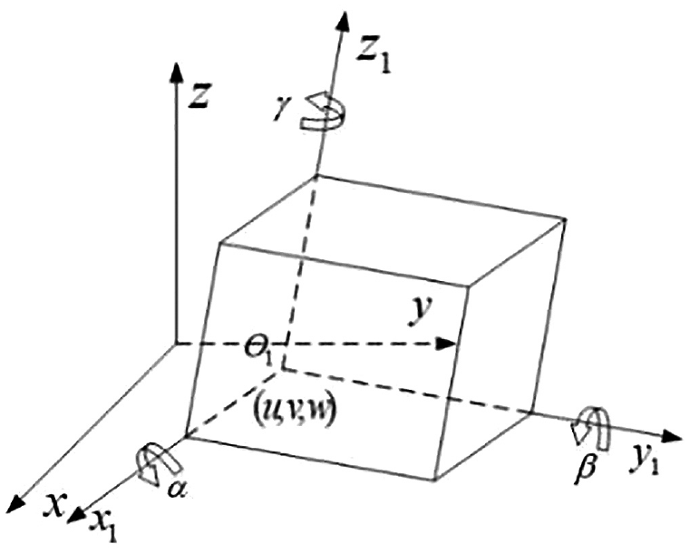
Torsor model for a feature.
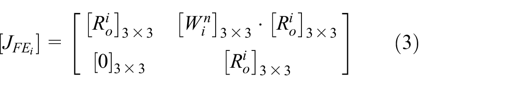
The tolerance propagation of the Jacobian–torsor model is realized by the Jacobian matrix, which expresses the small displacement of all functional elements (FEs) and functional requirement (FR). The Jacobian matrix transfers the errors of FEs generated by production or assembly to the end of the assembly and obtains the actual part assembly result FR that reflects the part design. The complete Jacobian matrix of the assembly is expressed as follows:

Where
In the Jacobian–torsor model, the functional elements are expressed by the following equations:
where

where
Figure 2 shows the details of the propagation of the assembly errors. For an assembly composed of many features, the expression of its Jacobian–torsor model can be represented by
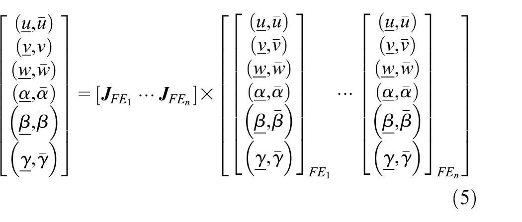
where

Propagation of assembly errors.
Multifactor coupled deformation extraction and tolerance conversion
The traditional tolerance analysis method assumes that the product is rigid and only considers the tolerance propagation of machining errors, such as design or manufacturing errors, ignoring the deformation caused by the operating conditions (temperature, load, vibration, etc.) of the product in service. The operating state of mechanical products will cause the parts to have small displacements, particularly the airborne equipment, and this will result in unreliable assembly accuracy analysis results. To solve this problem, we should consider the deformation of the actuator caused by actual operating conditions. A modified tolerance analysis model is generally divided into three parts: finite element analysis, tolerance extraction, and tolerance conversion. Tolerance extraction and conversion considering multifactor coupling are the most important steps in constructing a tolerance analysis model of the actuator cylinder considering deformation.
Deformation extraction
The extraction operation is a basic mathematical tool in the new generation of geometrical product specification (GPS) theory. It obtains a series of points from geometric elements according to a certain rule. In this process, points on nonideal elements are discretized according to specific rules, and these discrete points are used to approximate the features of the elements. The extraction operation is an important process for obtaining actual geometric elements. However, the actual deformation is not accessible under actual operating conditions. According to the method of the new-generation GPSs, using finite element simulation data to replace the actual product extraction of geometric elements can effectively solve the difficulty of extracting the actual geometric elements of mechanical products, and it has a relatively high calculation accuracy.
From the finite element results, we can extract the original node coordinates of the key functional features and deformation of the relevant coordinates along the three directions of the global coordinate frame. By superimposing the deformation of the relevant node with the original coordinate along the three directions, points representing the actual geometric surface can be obtained.
As shown in Figure 3, a cylinder feature is used as an example to illustrate the extraction process of an actual geometric element: First, the distribution of discrete points is obtained through an extraction operation of actual cylinder features. Second, the discrete points are divided into ideal cylinder features and the variable range of the cylinder.
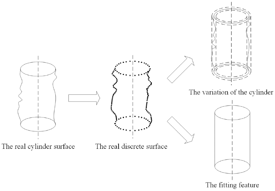
Geometric element extraction based on the GPS theory.
Figure 4 describes the geometric extraction process based on the finite element: First, a finite element simulation is built. Second, based on the simulation results, the deformation of the cylinder can be extracted, which can be divided into ideal cylindrical characteristics, and the displacement of the cylinder can vary. To display the variable range of the cylinder more directly, a schematic diagram of the radial deformation expanded along the cylinder is shown in Figure 5.

Geometric element extraction based on a finite element.
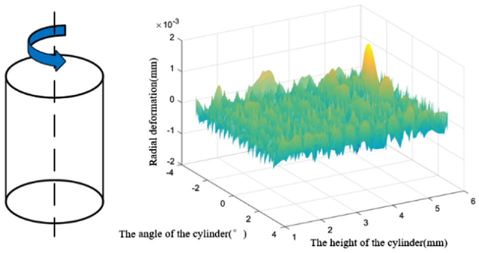
Radial deformation expanded along the cylinder.
The use of finite element deformation data solves the difficulty of extracting product deformations. Using this method, a discrete point finite element model that can accurately express the deformation was obtained.
Tolerances conversion
Tolerance conversion consists of feature fitting and deformation transition. Fitting approximates nonideal elements to ideal elements with certain rules. The aim is to describe the nonideal elements and obtain their characteristic values. The variation range of the ideal elements is obtained from the deformation transition. Through tolerance conversion, the deformation of mechanical products can be transformed into the relevant tolerance, and then a tolerance analysis model with multifactor coupling can be built. Therefore, tolerance conversion is an important step in constructing a tolerance analysis model that considers multifactor coupling.
Many researchers have studied the feature fitting theory. Commonly used mathematical fitting methods include the least squares method, minimum region method, unilateral Chebyshev method, maximum internal tangent method, and minimum external connection method. As shown in Figure 6, the specific equivalent method of deformation to the geometric error is as follows:
The dimension tolerance caused by deformation refers to the difference between the characteristic value of the fitted ideal feature and design size. The dimension tolerance of the deformed part can be obtained by subtracting the design size from the characteristic value of the fitted feature.
The orientation tolerance caused by deformation refers to the change in the actual position after fitting and in the ideal position. It equals the movement and rotation of the local coordinate system, which bounds the fitted feature to the theoretically correct position.
The form tolerance caused by deformation refers to the actual variable range of the ideal feature after the fitting. The actual variable range is denoted as the extreme value of the distance between the discrete point and cylinder.

Example of equivalent calculation of deformation.
According to the tolerance requirements of different features of the parts, we must match the relevant form tolerance. For example, for plane features, flatness should be selected as the equivalent target. For the surface, the cylindricity and surface profile can be selected as equivalent targets.
Multifactor coupled Jacobian–torsor tolerance analysis
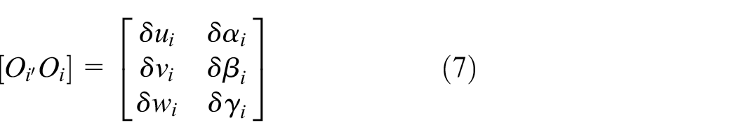
The torsor model uses screw parameters to represent small displacements of a feature within its tolerance zone. However, owing to the influence of temperature, load, and other environmental factors, the functional characteristics of the parts tend to change. These changes result in a small displacement of the parts. It is assumed that the deviation and ideal surface form tolerance can be superimposed and the actual form tolerance of the deformed parts can be obtained. The modified torsor model can be expressed as follows:

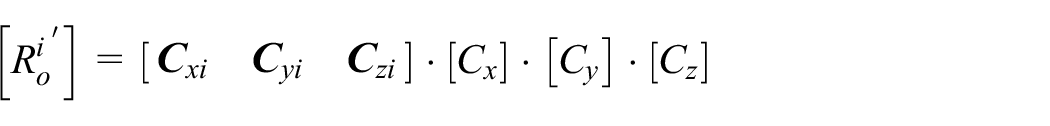
The torsor model modifies the form tolerance after deformation, and the Jacobian matrix modifies the dimensional tolerance and orientation tolerance after deformation. Owing to environmental factors, the feature dimension and location change, and these changes result in the transformations of the reference frame built by ideal characteristics. The change in the deformed feature consists of two parts: position movement and orientation movement. The following equation describes the transformation of the coordinate frame.
where
The modified change of the coordinate frame matrix
where


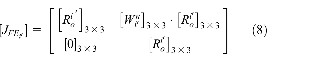
The modified Jacobian matrix

Example analysis
Hydraulic actuators are a critical part of aircraft control systems, and they are widely used in aircraft actuation. The operating environment of civil aircraft actuators is extremely special, and they must operate normally under high pressure and a wide temperature range. Most actuators are required to operate at temperatures of −50°C to 80°C and pressures of 30 MPa. Under such operating conditions, the assembly accuracy of the actuator is significantly affected. This study examined the influence of pressure and temperature on assembly accuracy, and an industrial application is described below. Figure 7 shows a simplified assembly and an exploded view of the actuator cylinder.
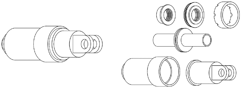
Assembly and exploded view of the actuator cylinder.
Actuator cylinder deformation under multifactor coupling
An actuator is used to drive the rudder of an aircraft to control its posture. It is simultaneously affected by high pressure and thermal load. It is required to drive the piston to operate normally at an operating pressure of 30 MPa and operating temperature of 50°C–80°C. However, the deformation caused by the multifactor coupling accumulates, which may result in a worse condition than a single factor and superpose the deformation caused by the operating stress. The deformation of this feature adversely affects the performance of the actuator. To study the effect of the parameters on the assembly accuracy, we investigated the effect of environmental factors on the deformation of the actuator. Finite element simulations were performed to determine the deformation of the actuator under single-factor and multifactor coupling conditions. The simulation results supported the construction of a tolerance analysis model.
Simulation of the deformation of the actuator cylinder under the influence of load
When the actuator was in a normal operating state, the pressure of the oil chamber was 30 MPa. To simplify the analysis process, we simplified the analysis model by eliminating the end cap and back cover in the modeling process. The construction process of the finite element model was as follows: (1) The simplified model was imported into Workbench, and the mesh was generated. (2) The contact relation between the piston and the inside and outside linings was set as the roughness. (3) The contact relationship between the cylinder and the inside and outside of the lining was set as the non-separation. (4) The pressure in the cavity was defined as 30 MPa, and the external surface of the cylinder and inner surface of the piston rod were set as fixed constraints. The deformation of the actuator cylinder under the operating load is shown in Figure 8.
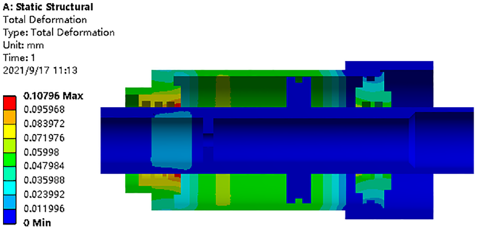
Deformation of actuator cylinder under the load.
As shown in Figure 8, the deformation was primarily concentrated on the outside lining, cylinder, and inside lining. The deformation of the outer lining was the most significant, with a value of 0.108 mm. The deformation of this key feature at the groove of the outside lining was approximately 0.072 mm, which was significantly larger than the design tolerance of the groove at 0.04 mm. Figure 9 shows the deformation distribution of the outer lining groove under load. The maximum radial deformation of the outer lining groove surface after deformation was 0.005 mm and the minimum was 0.001 mm.

Radial deformation expanded along the cylinder under the load.
Simulation of actuator cylinder deformation under the influence of thermal load
According to the experiment, the hydraulic oil temperature of the actuator cylinder was approximately 80°C, and the external surface temperature of the actuator cylinder was approximately 20°C under normal operating conditions. The steps for constructing the finite element model were as follows: (1) The simplified model was imported into Workbench and it was grided. (2) The temperature boundary condition of the actuating cylinder’s internal and external surfaces was set. The inner surface temperature was 80°C and the environmental temperature was 20°C. (3) The temperature distribution of the actuating cylinder was calculated, and the calculated results were sent to the static simulation. (4) The corresponding boundary conditions of the actuating cylinder were set as in Section 3.1.1. The deformation results under the influence of thermal load are shown in Figure 10.

Deformation of actuator cylinder under the thermal load.
As shown in Figure 10, the deformation was primarily concentrated on the outside lining, cylinder body, and inside lining. The deformation of the cylinder was the most significant with a value of 0.049 mm. The deformation of this key feature at the groove of the outside lining was approximately 0.04 mm, which was approximately equal to the design tolerance of the groove. Figure 11 shows the deformation distribution of the outer lining groove at different temperatures. As shown in Figure 11, the maximum radial deformation of the outer lining groove surface after deformation was 0.011 mm, and the minimum was 0.008 mm.

Radial deformation expanded along the cylinder under the thermal load.
Simulation of actuator cylinder deformation by thermo-mechanical coupling
To study the influence of the load and temperature on the actuator cylinder, we constructed a coupling model to obtain the deformation data. Owing to the operating temperature, the deformation of the actuator cylinder along each direction was small; therefore, the indirect coupling method was used to solve this condition. First, the corresponding temperature boundary conditions were set as shown in Section 3.1.2 to calculate the temperature distribution of the actuator cylinder. Second, the calculation results were imported into a static simulation. Third, the boundary conditions and oil pressure in the actuator cylinder were set. The deformation of the actuator cylinder under the thermo-mechanical coupling effect is shown in Figure 12.
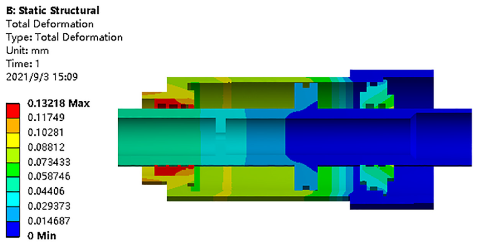
Deformation of actuator cylinder with thermo-mechanical coupling.
As shown in Figure 12, the deformation was primarily concentrated on the parts of the outside lining, cylinder body, and inside lining. The deformation of the outside lining was the most significant, with a value of 0.132 mm. The deformation of this key feature at the groove of the outside lining was approximately 0.13 mm, which was significantly larger than the design tolerance of the groove. Figure 13 shows the deformation distribution of the outside lining groove under the coupling effect of multiple factors. The maximum radial deformation of the outside lining groove surface after deformation was 0.018 mm and the minimum was 0.012 mm; this deformation was larger than that caused by temperature and pressure.
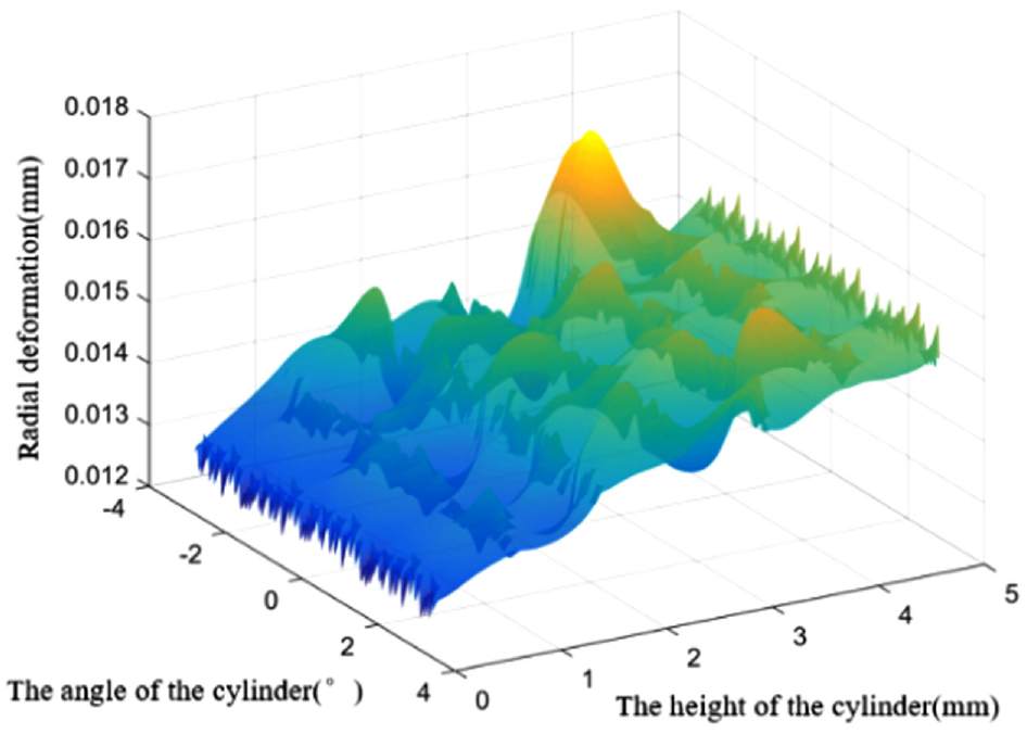
Radial deformation expanded along the cylinder with thermo-mechanical coupling.
Tolerance modeling of actuating cylinder under multifactor coupling
The traditional and modified Jacobian–torsor models were constructed to determine the assembly accuracy law of the actuator under multifactor coupling. The tolerance analysis results of the calculation examples were compared to determine the differences between the two tolerance analysis models.
Establishment of the Jacobian–torsor model
A global coordinate frame was established based on the outer surface of the piston rod, and a local coordinate frame was established based on the functional characteristics of the part. The details of each coordinate frame are shown in Figure 14. All local coordinate frames were established in the theoretical middle of the feature or assembly center position.

Relative position of each local coordinate frame.
Considering the influence of the functional characteristics, tolerances, and assembly characteristics of the parts, the part assembly relationship diagram can be constructed using graph theory (Figure 15). Figure 15 shows the relationship between the outside lining and outer surface of the piston rod, indicating the assembly connection form of the component in series.
Functional connected relation.
We can observe from Figure 15 that a tolerance transfer path exists for this assembly:

The Jacobian matrix and torsor model of each functional feature were calculated, as shown in Table 1.
Jacobian matrix and characteristic torsor model before deformation.
Using the Jacobian–torsor method and substituting the deformed data into equation (10), the calculated results were obtained as follows:

Construction of Jacobian–torsor model under multifactor coupling
Based on Section 3.1.3, the deformation information data of the required surface were extracted to obtain the finite element discrete surface information. Subsequently, we wrote a program that could fit the data to a cylinder model. The program was based on the MSAC method, which can fit the extracted data well. It can also significantly eliminate the “noise points” generated by the calculation and effectively avoids the analysis and judgment process of the initial test data with good robustness and accuracy. The distribution of the points before and after deformation is shown in Figure 16, where the red points indicate the positions of the feature points before deformation, and the blue points indicate the positions of the feature points after deformation.

Distribution of points before and after feature deformation.
Using the MSAC surface fitting method, the deformed cylindrical model, which can obtain information about the translational and rotational movements of the deformed cylindrical features, can be obtained. The program uses the finite element discrete surface points as input and determines the optimal solution that satisfies the conditions by controlling the maximum distance from the point to the fitted position. The fitting results are shown in Figure 17.

Fitting cylindrical model.
From the results of the program, the radius of the fitted cylindrical surface was 22.1172 mm, which was caused by the influence of deformation. The direction vector was (0.0243, −0.0080, −4.8855), and the local coordinate system position was (−0.0083, −0.0018, 0.0541). The radius of the original cylindrical surface is 22.11 mm, the direction vector was (0, 0, 1), and the local coordinate system position was (0, 0, 0). Figure 18 shows that the deformed surface expanded along the fitted cylinder. The cylindricity of the feature was calculated to be 0.005 mm. Table 2 lists the relevant parameters after the deformation.
Deformed surface expanded along the fitted cylinder.
Characteristic parameters after deformation.

The local coordinate system built on the parts changed owing to the deformation of parts in the actuator cylinder influenced by multifactor coupling. The Jacobian matrix and characteristic torsor models after the deformation are listed in Table 3.
Jacobian matrix and characteristic torsor model after deformation.
Using the Jacobian–torsor method, we substituted the data into equation (10). The calculated results were obtained as follows:

By comparing the results of the tolerance analysis before and after deformation, we observed that the multifactor coupling environment reduced the assembly accuracy of the target feature. Without considering the deformation, the tolerance between the outer surface of the piston and the groove of the outside lining in the direction y was (−0.1374, 0.1374), while the tolerance in the direction y was (−0.1999, 0.1999) considering the deformation. This result indicated that the deformation resulted in poor accuracy of the distance from the outside lining groove to the piston surface. Using the traditional method to predict assembly accuracy may result in unreliable results. If the tolerance is still assigned as usual, abrasion between the sealing ring and outer surface of the piston is inevitable. Therefore, it is necessary to consider reducing the dimensional tolerance of the groove or increasing the basic dimensions of the feature to compensate for the deformation caused by environmental factors. The result also explains the phenomenon of abnormal abrasion of the sealing ring when performing a movement, and it may reveal the essential reason for the poor performance of the actuator in the operating state.
Conclusion
Based on the small screw theory and Jacobian model, this paper presents a novel approach to analyzing product assembly errors considering the coupling of multiple factors. This method and the traditional method were used to analyze the actuator tolerance, and the results of the tolerance analysis were compared. We observed that the new method reflected the actual accuracy of the assembly, and the analysis result was larger than that calculated using the traditional method. This conclusion explains the abnormal abrasion phenomenon of the actuator cylinder under the operating conditions.
Using the new GPS theory, the deformation of the product was extracted from the finite element model, and then the deformation was converted to the tolerance of dimension, orientation, and form to consider the influence of the deformation. Additionally, this study investigated the specific rules of deformation conversion to tolerance.
In this study, a finite element simulation of a single factor and multiple factors was performed to investigate the assembly and accuracy of the actuator. The results indicated that the deformation of the actuator with multifactor coupling was larger than that of the single factor and also larger than the sum of the single factors.
In this study, an airborne actuator was considered as an example to build an assembly error analysis model under multifactor coupling. The assembly state of the actuator was analyzed more accurately by considering its deformation. The results clarified the effects of the operating state on the assembly accuracy of the actuator from the perspective of tolerance, thereby supporting the subsequent improvement of the actuator.
Footnotes
Acknowledgements
The authors would like to thank the editor and reviewers for their detailed comments which helped to improve the quality of this paper.
Handling Editor: Chenhui Liang
Contributions
All the authors contributed significantly to the work with the order provided.
Declaration of conflicting interests
The author(s) declared no potential conflicts of interest with respect to the research, authorship, and/or publication of this article.
Funding
The author(s) disclosed receipt of the following financial support for the research, authorship, and/or publication of this article: This work is supported by Science, Technology and Innovation Commission of Shenzhen Municipality (JCYJ20190806151013025).
Consent for publication
All the authors have reached agreement for publication.