
Abstract
In the machining of a five-axis machine tool with a double turntable, the dynamic characteristics of the machine tool are affected by different spatial positions of workpieces. Predicting the dynamic characteristics of machine tools at different spatial positions can effectively improve the machining accuracy of workpieces. In the present study, a five-axis CNC machine tool (Tuopu VMC-C50, China) is considered as the research object. Firstly, the bearing stiffness model of the double turntable rotary system is established, and the influence of the joint stiffness of the turntable bearing on the dynamic characteristics of the five-axis machine tool table rotary system is studied. Based on the established three-dimensional model and rigidity of the sliding joint surface of the machine tool, the machine tool modes at 81 working positions are analyzed. Accordingly, the influence of different swinging positions of the double turntable on the dynamic characteristics of the five-axis machine tool is studied. Finally, based on the three-dimensional Kriging prediction model, variations of the natural frequency and vibration amplitude of the system in the machining space for different swing table angles are analyzed.
Introduction
Machining accuracy is an important indicator in evaluating the performance of CNC machine tools. In this regard, the dynamic characteristics of CNC machine tools are essential factors affecting machining accuracy and stability. With the rapid development of intelligent manufacturing technology, the quality requirements of machine tools are continuously becoming stricter. The improvement is especially more pronounced to reach better dynamic characteristics of machine tools. During the operation of the five-axis machine tool with a double turntable, the space position of the moving axis constantly changes due to the movement of the X-, Y-, Z-, A-, and C-axes of the rotating axis, thereby changing the rigidity of the machine tools. It is worth noting that the dynamic characteristics of the machine tool are different in each machining position. Consequently, predicting the dynamic characteristics of the machine tool when the workpiece is in different machining positions can effectively improve the machining accuracy of the workpiece.
Studies show that the dynamic characteristics of a mechanical system is affected by its structure and the contact quality between different structural components. To analyze the dynamic characteristics of machine tools, numerous virtual prototypes have been developed. Moreover, numerous investigations have been carried out to analyze and optimize the performance of machine tools and test works. 1 In this regard, Mi et al. 2 used ANSYS software to model a horizontal machining center and analyze the machine mode. Although remarkable achievements were obtained, the dynamic characteristics of various key components were not considered in this study. Liu et al. 3 established a generalized modal function and a generalized stiffness field function to describe the dynamic characteristics of CNC machine tools at different machining positions. It was found that the optimal machining attitude of the tool follows the spatial variation of natural frequency and dynamic stiffness. However, the combined rigid body motion and vibration were not considered in the established function. Law et al. 4 proposed a reduced-order substructure finite element model to evaluate the position-dependent stability of machine tools. However, the identified weak machine tool components were not analyzed when the machine tools were reassembled. Baumann et al. 5 analyzed the dynamic characteristics of the machine tool by analyzing the machining position and machining path of the machine tool. They obtained the frequency response function by obtaining the dynamic characteristic information of limited positions. Although this method was effective in considering the tool-position-dependent change of modal parameters in a geometric-kinematic simulation system, the influence of the rotational axis’ configuration on the machine tool was not considered. Nam et al. 6 studied the dynamics of multibody five-axis machine tools and proposed a model to predict the combined rigid body motion and vibrations of the machine. However, during experimental modal analysis tests, individual motions around the rotational axes of the table were not considered comprehensively. Deng et al. 7 developed a method to study the regularity of the dynamic characteristics of the whole machine tool in the generalized manufacturing space. In this regard, a generalized dynamic response model was developed by combining the response surface method (RSM) and the orthogonal design of the experiment method. The model contains information on the spatial position and spindle-bearing dynamic parameters. However, the connection between the spindle system and the gripper-tool system, and the dynamic information of the rotary table cannot be obtained in the machining space. Barbosa et al. 8 studied the three-dimensional free vibration and converted the domain integral of the system inertia into the boundary integral. By solving the Helmholtz equation, the dynamic model of the natural spectrum was determined. It should be indicated that most of the reviewed investigations were based on the dynamic characteristics analysis of the spindle at different machining positions, while there are few articles about the influence of the spatial position of the double turntable swing on the dynamic characteristics of the five-axis machine tool.
Moreover, since the moving parts of the machine tool may be in different spatial positions during machining, it is necessary to carry out machining path planning and tool attitude control to fit the dynamic characteristics of the whole machining space to the dynamic characteristics of the limited observation points in the machining space. Aiming at providing a new method for data fitting of modes in unknown machining space, Hu et al. 9 proposed a method to smoothly interpolate the dynamic characteristics of machine tools. Gao et al. 10 proposed a model based on the Kriging method and obtained the dynamic characteristic spectrum of the machine tool. Furthermore, Li Tianjian et al. 11 used the spatial statistics method to explore the dynamic characteristics of the machine tool and fit the dynamic spectrum of the machine tool. Varatharajan, 12 Zhong, 13 Deng 14 and others used Kriging interpolation in the research method of spatial fitting, which provides a relatively accurate prediction method for studying the spatial dynamic characteristics of the machine tool machining. The performed literature survey indicates that different methods such as studying machine tool dynamics, 15 conducting numerical simulations and modal analyses on the machine tool under specific working postures, 16 and adopting different interpolation methods for unknown working conditions 17 have been developed to interpolate the machine tool’s position and posture. Although some achievements have been made, these methods have certain limitations in fitting accuracy and range.
In the present study, it is intended to establish the bearing stiffness model of the double turntable rotary system. The main objective of this article is to investigate the influence of the stiffness of the bearing joint on the dynamic characteristics of the rotary system of the five-axis machine tool. To this end, a three-dimensional model of the double turntable five-axis CNC machine tool is established. Then the machine tool modes at different machining positions are analyzed. Finally, the basic mode field of the machine tool machining space is established based on the three-dimensional Kriging interpolation method, and the dynamic characteristics of the machine tool machining space are analyzed accordingly.
Establishment of bearing stiffness model of the double turntable rotary system
The basic structure of the double turntable rotary system
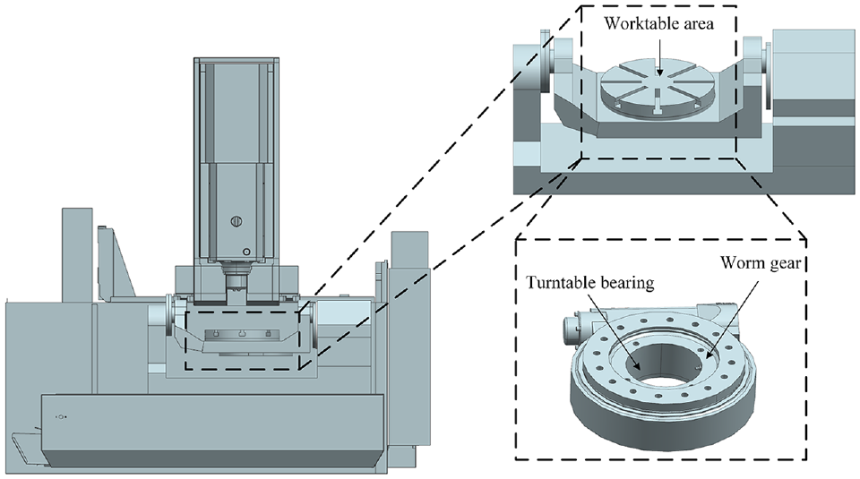
The dynamic characteristics of the rotary system significantly affect the positioning accuracy and machining performance of the five-axis machine tool. In the present study, a five-axis CNC machine tool (Tuopu VMC-C50, China) is considered as the research object. The schematic structure of the machine is shown in Figure 1. The main features of the studied CNC machine are shown in Table 1. The transmission mechanism of the table mainly includes a worm gear and a worm drive, and the main mechanical joints include a turntable bearing joint, a worm gear joint, a fixed joint, and a swing-arm bearing joint.
AC dual-axis turntable five-axis machine.
Main features of the studied CNC machine.

As the indexing and positioning component of the machine tool, the supporting stiffness of the turntable not only affects the static deformation of the table, but also the dynamic stiffness of the double turntable rotary system and the cutting stability and machining accuracy of the workpiece. The turntable and worm gear are connected to the base through bearings, whose static stiffness directly affects the geometric accuracy and dynamic characteristics of the table. The bearings can bear axial and radial loads and an overturning moment at the same time. Figure 2 shows that a YRT bearing of the double swing table mainly consists of a shaft ring, a seat ring, two rows of axial cylindrical rollers, a row of radial cylindrical rollers, and a cage.

Structure diagram of a YR-type turntable bearing.
Establishment of stiffness model of the turntable bearing
In order to improve the convergence rate and the computational efficiency, the bearing stiffness is theoretically calculated based on the following assumptions: the seat ring, washer, and shaft ring are rigid bodies and do not deform. The deformation occurs only on the axial roller, radial roller, and contact areas. The seat ring is stationary, while the shaft ring has relative displacement under the action of external loads. The rotating speed of the table does not exceed the upper limit, and the centrifugal force is negligible.
A YRT-type bearing is a high-precision three-row roller turntable bearing that can tolerate combined loads. It is widely used in the rotary parts of precision instruments such as machine tools, engineering machinery, and rotating parts in the aerospace industry. Its axial direction is bidirectional thrust cylindrical roller bearings. The roller contacts two planes. Elastic convergence of the cylindrical roller 18 can be obtained from the following expression:
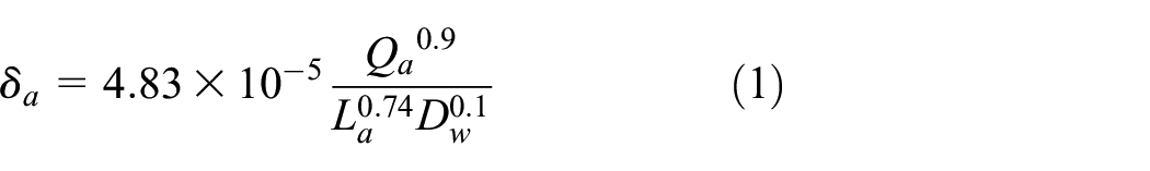
Based on equation (1), the single axial roller load Qa can be expressed as follows:

Where Qa is the load of a single axial roller, La is the length of the roller, Daw is the effective diameter of the axial roller, and δa is the elastic approach value along the axial direction.
Since the YRT-type bearing is axially preloaded with a negative clearance Ga, deformations of the two rows of axial cylindrical rollers on each contact surface are equal. In other words, the axial cylindrical rollers on each contact surface approach elastic deformation δa = Ga/4. Therefore, equation (2) can be rewritten in the form below:

In this problem, it is assumed that a load of ΔFa(N) is applied to the bearing so the total elastic produced by the rolling element and raceway is equal to 1 μm. Under these circumstances, the stiffness of the bearing can be considered as ΔFa (N/μm) indicating that only ΔFa is required to obtain the axial stiffness Ka.
When the total elastic deformation of the bearing along the axial direction reaches 1 μm, the stiffness of the bearing is ΔFa (N/μm). The increasing value of the approaching amount between a cylindrical roller and a contact surface is

Considering the negative axial clearance concept, the same load is applied to all rolling elements. Accordingly, an increase of one unit of load ΔQa on each rolling element can be expressed in the form below:

Where Za denotes the number of single-row axial cylindrical rollers. Moreover, ΔFa (N/μm) reflects the axial stiffness Ka (N/μm) of the bearing in the state of negative clearance Ga. Combining equations (4) and (5) yields the following expression:

Since the radial dimension of the rotary table bearing is much larger than the length of the cylindrical roller, the relationship between the contact deformation and force of the axial roller can be described using the ideal plane contact. Ignoring the centrifugal force, the contact deformation and angle between the axial roller and inner and outer rings are equal. Equation (6) indicates that the initial clearance of the axial roller can be determined by the pre-tightening force of the fastening screw. Since the screw is pre-tightened, initial clearances of axial rollers are negative. Under the influence of external load Fa, the axial clearance Ga of the axial roller under a given screw tightening torque can be calculated using the following expression:

Where Zb is the number of screws, T is the tightening torque, db is the screw diameter, and Kb is the screw torque coefficient, which is usually set to 0.2. 18
The bearing can be regarded as cylindrical roller bearing in radial direction, so the radial stiffness of a YRT-type bearing can be calculated similarly to the radial stiffness of a cylindrical roller bearing. In a linear contact cylindrical roller bearing, the elastic convergence between the roller and the raceway is defined in the form below:

Where Qr is the load on the single radial roller, Lr is the length of the roller, and υ1, υ2 are the Poisson’s ratio of the roller and ring materials, respectively; Moreover, E1 and E2 are the elastic moduli of the roller and ferrule materials, respectively.
It should be indicated that equation (8) is only applicable to the calculation of elastic approach δr of rolling bearings with raceway diameter of 20–70 mm. Considering the convexity-concavity of curvatures of the roller and raceway, equation (8) can be modified in the form below:
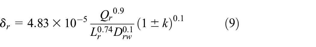
Where Drw and Dr are the effective diameters of the roller and the raceway, respectively. Moreover, k denotes the ratio of the effective diameter of the rolling element to the raceway diameter Drw/Dr. When the roller contacts the inner raceway, k is calculated as “+,” and when it contacts the outer raceway, k is calculated as “−.” When the roller contacts the inner and outer raceways simultaneously, the total normal displacement of the roller is the sum of the elastic convergence of the inner and outer raceways. The maximum rolling element force subjected to the radial load in the zero-clearance state can be calculated as follows:

Where Zr and Fr denote the number of radial cylindrical rollers and the radial load, respectively. Similarly, the radial stiffness can be calculated from the following expression:

Where Gr is the initial clearance of the radial roller.
Analysis of dynamic characteristics of double turntable rotary system
To establish a three-dimensional geometric model, the rotary system is imported into the ANSYS environment. The structural model of the rotary system is simplified before establishing a finite element model. In the established mode, the turntable body is in the middle of the double swing table, including the worktable, turntable bearing, worm gear, and body. It should be indicated that the holes, grooves, and chamfers are ignored in the model. Figure 3 shows the structural model and the meshed model of the rotary system.

The established finite element model for the studied double-turn table: (a) 3D model diagram and (b) meshed model.
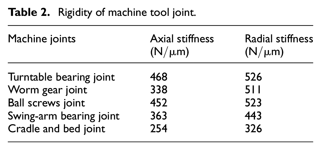
Then the boundary conditions of the joint surface and components are set. The fixed joint surface is bolted, which is set as default. The setting of joint surface stiffness of the double turntable rotary system is shown in Table 2, and a spring is used between the contact surfaces. In the established model, 108,959 tetrahedral meshes with a size of 10 mm were used.
Rigidity of machine tool joint.
To study the impact of the stiffness of the bearing joint on the dynamic characteristics of the double turntable rotary system of the five-axis machine tool, the turntable shown in Figure 3 is considered as the research object. The dynamic characteristics of the rotary system of the five-axis machine tool table with a swing angle of

Model contours of the first six modes of the double turntable: (a) The first-order modal; (b) The second-order modal; (c) The third-order modal; (d) The fourth-order modal; (e) The fifth-order modal; (f) The sixth-order modal.
The first six natural frequencies of the double turntable.
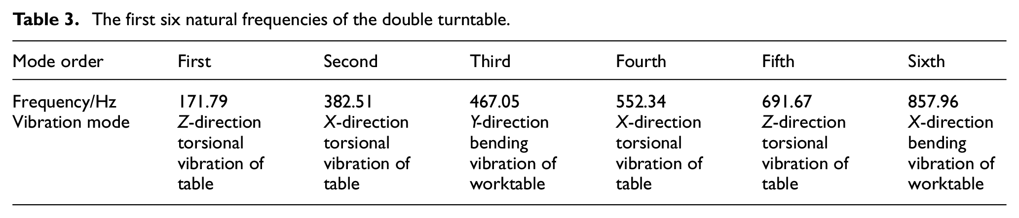
It is observed that the main vibration pattern of the first six modes mainly appears below the C-axis turntable where the power is transmitted through a worm gear. Considering the low stiffness of the worm gear teeth, this point is the weakest point in the entire C-axis turntable transmission system, which reduces the overall stiffness of the double rotary table and limits the overall first-order natural frequency of the double rotary table.
The modal analysis of the double rotary table system was carried out at different swing angles, and the first six natural frequencies of the double rotary table system are presented in Table 4. It is observed that as the swing table angle increases, the first-order natural frequency of the swing table decreases first and then increases. The natural frequency of the swing table with a positive angle is larger than that with a negative angle; Table 3 indicates that the largest natural frequency is 191.62 Hz, which occurs at 60°; Meanwhile, as the swing angle changes, the corresponding first-order natural frequency of the swing table changes at 78.49 Hz.
First-order frequency parameters of machine tool under different positions of the swing table.

Influence of double turntable swing on dynamic characteristics of the five-axis machine tool
When establishing the geometric model and simulating the system, it is necessary to set the parameters according to the unique characteristics of the double turntable five-axis machine tool. When the size of the geometric details is much smaller than the size of the components, these geometric details can be ignored.
The three-dimensional model of the five-axis double-turntable CNC machine tool is shown in Figure 5(a). In the first step, the established three-dimensional model in the UG NX platform is imported into the ANSYS environment. The bed material of the machine tool is cast iron HT250 with a density of 7200 kg/m3, elastic modulus of 110 GPa, and a Poisson’s ratio of 0.28), other material parameters are also set according to the instructions. Then the boundary conditions are set. The fixed joint surface of the machine tool is mainly bolted and the spring unit is set between the contact surfaces. The stiffness settings of the linear guide pair and the ball screw pair are shown in Table 5. Figure 5(b) shows that the entire machine tool model was meshed with 353966 units. The mesh independence test is carried out. 19

3D model and prepared meshes of the studied five-axis machine tool: (a) 3D model; (b) Meshed model.
Rigidity of the machine tool joint surface.

Modal simulation of machining space machine tool with fixed double turntable
In this section, static calculations were carried out and the stress distribution was obtained. During analyses, the nonlinear characteristics of the joint were ignored. Figure 6 shows the coordinates of the machining space of the machine tool and angle change direction, indicating that the end of the machine tool spindle is considered as the coordinate origin and a cube with a side length of 300 mm is used as the processing space. There are 27 observation points in the processing space and x14 is the coordinate origin. The table can take three different θ degrees, including θ = 0°, θ = 90°, and θ = −90°. Consequently, there are 81 (=27 × 3) observation points in total. The initial position of the turntable (A = 0°) can be interpreted as the turntable plane is parallel to the horizontal plane. Figure 7 shows the first-order mode of six spatial position points when the swing table is at θ = 0°.
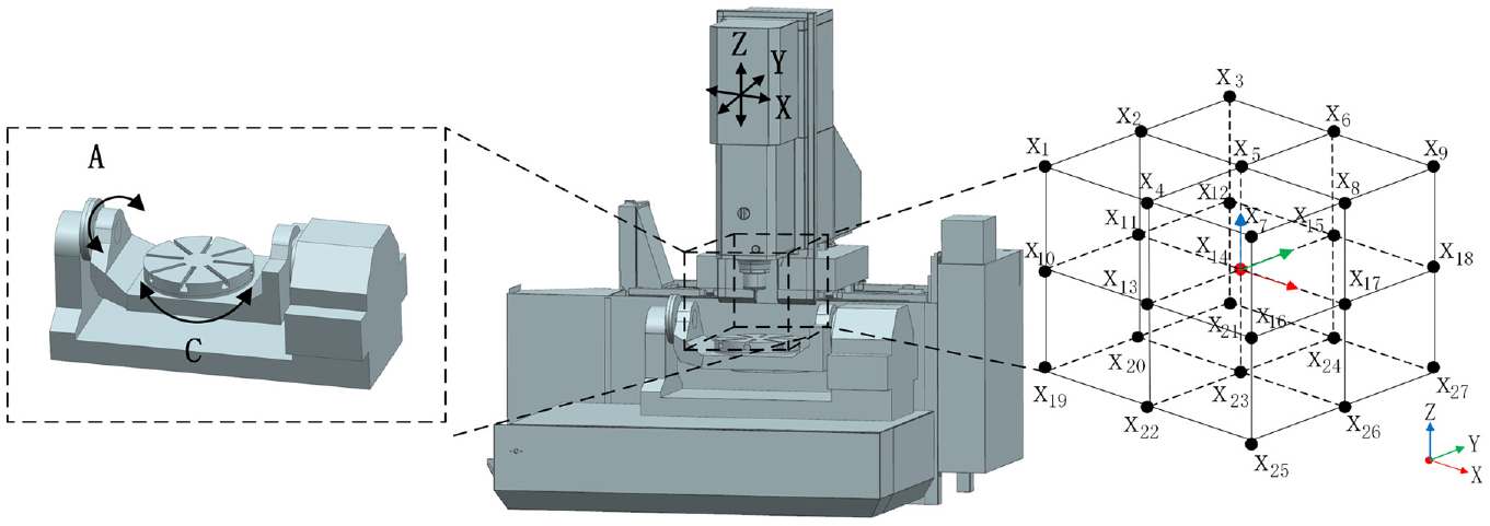
The spatial position of observation points of the five-axis machine tool.

Model contours of the first mode of the machine tool in the spindle end: (a) x = 0 mm, y = 0 mm, z = 0 mm, θ = 0°; (b) x = 150 mm, y = 0 mm, z = 0 mm, θ = 0°; (c) x = 0 mm, y = 150 mm, z = 0 mm, θ = 0°; (d) x = 0 mm, y = 0 mm, z = 150 mm, θ = 0°; (e) x = 0 mm, y = 0 mm, z = 0 mm, θ = −90°; (f) x = 0 mm, y = 0 mm, z = 0 mm, θ = 90°.
After determining the movement direction of each axis of the machine tool, the machine tool moves along the desired direction using the control variable method. It is observed that as the machine tool moves, the first-order natural frequency of the machine changes, and the amount of change is different. Consequently, it is necessary to conduct an in-depth study on the variations of the natural frequency along each axis separately.
Modal Simulation of the Machine tool with double turntable rotation
In this section, it is intended to perform modal analysis on all spatial positions of the spindle end of the dual-turntable five-axis machine tool. In this regard, Figure 8 shows the contours of the first six-order modal analysis of the five-axis machine tool at the end of the spindle of the machine tool. The sixth-order modal parameters and mode shapes at this point are shown in Table 6. With the increase of modal order, the natural frequency increases rapidly.

Model contours of the first six modes of the machine tool: (a) The first-order modal; (b) The second-order modal; (c) The third-order modal; (d) The fourth-order modal; (e) The fifth-order modal; (f) The sixth-order modal.
The natural frequency of the first six orders of the double turntable five-axis machine tool.

Similarly, the modal analysis is carried out at all 81 machining positions at the end of the spindle. Table 7 shows the first-order natural frequencies of the five-axis double-turntable CNC machine tool. When the swing angle is set to −90°, and the spindle end machining position is set to X = 150 mm, Y = −150, and Z = 150 mm, the corresponding natural frequency reaches its maximum value of 53.4 Hz.
Modal parameters of the machine tool in different position.

Analysis of the dynamic characteristic spectrum of the machine tool based on the Kriging model
Kriging prediction model 20 can fit unknown spatial object-related information based on known spatial samples. It is essentially an improved regression algorithm, which uses covariance to measure the correlation degree between points in space. This model mainly consists of two parts, including the linear regression part and the variogram part. Kriging optimal interpolation method is an unbiased estimation method based on minimum variance estimation and has been widely used to approximate response functions.
In order to study the dynamic characteristics of the machining space of the five-axis CNC machine tool with a double turntable using the Kriging prediction model, the dynamic characteristics of the entire machining space are fitted based on the dynamic characteristics of the 27 observation points.
Assume

Where λi is the weight coefficient, which represents the contribution degree of 27 spatial sample points
The weight coefficient should satisfy the unbiasedness and optimality conditions. Unbiasedness conditions can be expressed in the form below:

The average error of the four variograms, including the spherical model, exponential model, Gaussian model, and power function model was obtained by cross-validation. 20 The Gaussian model had the smallest error so it was selected as the variograms of the kriging model. Then the established kriging prediction model of the Gaussian function was introduced into kriging equations, and the corresponding weight coefficients under 27 spatial positions were calculated. Finally, point x0 was estimated.
In the dynamic analysis of structure, the weight coefficient of each mode has a negative correlation with the mode frequency, indicating that the dynamic performance of the machine tool is basically determined by the low-order mode characteristics. The obtained results in the previous sections reveal that the first-order mode has the greatest impact on the vibration of the machine tool structure. The lower the frequency, the easier it is to be incentive by the outside world. Accordingly, the first-order mode is mainly studied in the modal analysis. The obtained first-order modal data is imported into the kriging model for data fitting, and the Gaussian variation function is used as the various function of the kriging model to establish the first-order natural frequency field and the maximum amplitude field of vibration in the processing space of a double turntable five-axis CNC machine tool. Modal analysis is used to determine the vibration characteristics of structures and design the machine parts. Figures 9 and 10 show the first-order natural frequency of the machining space of the five-axis machine tool for different angles of the swing table. The value range of X-, Y-, and Z-axis is −150–150 mm.
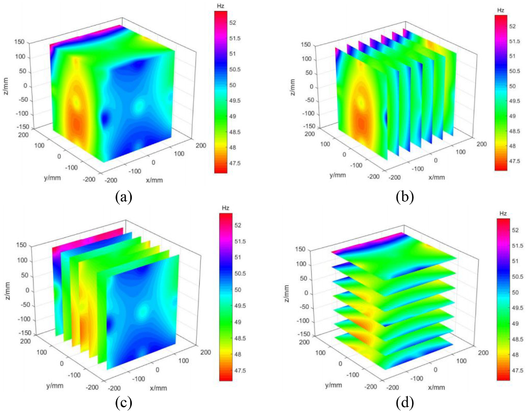
The first-order natural frequency of the processing space at a swing table angle of θ = 0°: (a) natural frequency, distribution of the natural frequency along (b) X-direction, (c) Y-direction, and (d) Z-direction.
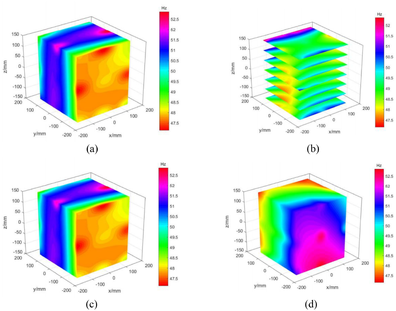
The first-order natural frequency field of the machining space at different swing angles: (a) θ = -45°, (b) θ = 45°, (c) θ = −90°, and (d) θ = 90°.
The modal superposition method 21 is used to analyze the harmonic response of the machine tool. The amplitude of the harmonic response force is 200 N and the virtual X-axis is taken as the center point of the machine tool moving platform. Based on the obtained results from the modal test, the damping ratio of the machine tool structure is set to 0.02. Moreover, the solution frequency band is set to 20–60 Hz and the load step is 20 and the harmonic response solution is obtained in this frequency band. Figures 11 and 12 illustrate the maximum vibration amplitude of the machining space subjected to the cutting excitation for different angles of the swing table. Moreover, variations of the vibration amplitude along the X-, Y-, and Z-axes are 0.06, 0.2, and 0.16 μm, respectively. It is found that the vibration amplitude along the Y- and Z- axes is significant during the movement.

The maximum amplitude field of the processing space of the swing table at θ = 0°: (a) Maximum vibration amplitude field, distribution of the maximum vibration amplitude along (b) X-direction, (c) Y-direction, and (d) Z-direction.

The maximum amplitude field of the machining space of the swing table at different swing angles: (a) θ = −45°, (b) θ = 45°, (c) θ = −90°, and (d) θ = 90°.
Figure 13 depicts the first-order natural frequency of the machine tool based on the machine status. It is found that the frequency changes along the X- and Z- axes are relatively large, while the variations along the Y-axis are relatively low. Moreover, Figure 14 shows the frequency value that mainly appears in the processing space with different swing table rotation angles.

Variations of the natural frequency along each axis during table swing at θ = 0°.

Variations of the natural frequency of machining space at different swing angles.
It should be indicated that the actual machining space changes with the change in the swing angle of the swing table. Therefore, the frequency and amplitude of the position on the actual machining space are used as the basis of the fitting process.
Figures 13 and 14 reveal that it is of significant importance to keep the X-axis in the middle of the machine tool, give the priority to the Y-axis, and limit the motion of the Z-axis. Under these circumstances, the swing table reduces the dynamic characteristics of the machine tool in ultra-precision machining. The lowest natural frequency of the whole machine is achieved when the swing angle of the swing table is set to 0°. Meanwhile, it is observed that as the swing angle of the swing table increases gradually, the natural frequency of the whole machine also increases and the highest natural frequency of the whole machine occurs at 90°. When the swing angle of the swing table is set to −90° and the machining position of the spindle end is at X = 150 mm, Y = −150, and Z = 150 mm, the natural frequency reaches 53.4 Hz. This is the highest natural frequency of the system. It was found that the frequency change of the X-, Y-, and Z-axis are 2.7, 0.8, and 6.2 Hz, respectively.
During the operation of the double turntable five-axis machine tool, the spatial position of the machine tool’s motion axis changes constantly, which affects the machine tool’s stiffness. The maximum amplitude of each processing position of the machine tool under the first-order natural frequency also changes. Figure 15 shows the swing table rotation angle at θ = 0°. It is found that the frequency change is large along the Y- and Z-axes, while it is relatively low along the X-axis. Figure 16 shows the maximum vibration amplitude for different swing table rotation angles. When the swing angle of the swing table is set to 45° and the machining position of the spindle end is at X = 150 mm, Y = −150 mm, and Z = −150 mm, the vibration amplitude of the system is 2.87 μm. At these settings, the amplitude change is the largest and the corresponding natural frequency is 50.1 Hz.
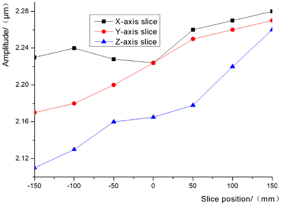
Variations of the vibration amplitude along the three axes at θ = 0°.

Variations of the vibration amplitude of the machining space for different swing angles.
The maximum vibration amplitude is shown in Figures 15 and 16. It is observed that the lowest vibration amplitude is achieved when the rotation angle is set to θ = 0°. In the studied range of the swing angle, the vibration amplitude changes about 0.14 μm. Moreover, it is found that as the rotation angle of the swing table increases, the vibration amplitude increases first and then decreases. The maximum vibration amplitude of the spindle end of the machine tool occurs at 45°. The prediction of machining space dynamic characteristics of the above machine tools can be fitted for tool attitude control.
Conclusion
In this paper, a five-axis CNC machine tool (Tuopu VMC-C50, China) is considered as the research object. The bearing stiffness model of the double turntable rotary system is established. The influence of the stiffness of the bearing joint and the swing positions on the dynamic characteristics of the five-axis machine tool rotating system are analyzed. The main achievements of this article can be summarized as follows:
A three-dimensional model was proposed to simulate the five-axis double turntable machine tool and then the modal analysis was carried out. The first six-order modal simulations were performed on 81 machining positions in the machining space and the stiffness of the sliding interface of the machine tool was modified based on the performed modal analysis. According to the spatial statistics method, the Gaussian variogram was used as the variogram and the three-dimensional Kriging prediction model was applied to fit the swing angle of the swing table at −90°, −45°, 0°, 45°, and 90°. The first-order natural frequency of the machining space was obtained and the dynamic characteristics were calculated.
When the swing angle of the swing table is set to −90° and the machining position of the spindle end is at X = 150 mm, Y = −150 mm, and Z = 150 mm, the natural frequency reaches 53.4 Hz. This is the highest natural frequency of the system and vibration amplitude reaches 2.13 μm. It was found that the frequency change of the X-, Y- and Z-axis are 2.7 Hz, 0.8 Hz, and 6.2 Hz, respectively. It is inferred that the Y-axes should be given priority during the machining process, while the motions along the X- and Z-axes should be limited. It was also found that variations of the swing table angle affect the natural frequency of the machine tool. The mesh convergence study revealed that when the swing angle of the table changes from 0° to 90° and −90°, the natural frequency of the machine tool changes about 1.5 Hz.
When the swing angle of the swing table is set to 45° and the machining position of the spindle end is at X = 150 mm, Y = −150 mm, and Z = −150 mm, the vibration amplitude of the system is 2.87 μm. At these settings, the amplitude change is the largest and the corresponding natural frequency is 50.1 Hz. Moreover, variations of the vibration amplitude along the X-, Y-, and Z-axes are 0.06, 0.2, and 0.16, respectively. It is found that the vibration amplitude along the Y- and Z- axes is significant during the movement. Variations of the swing angle of the swing table affect the natural frequency of the machine tool. In the studied range of the swing angle, the vibration amplitude changes about 0.14 μm.
The obtained results are expected to provide a new design analysis method and technical support for the dynamic design of precision machine tools. The prediction of machining space dynamic characteristics of the above machine tools can be fitted for tool attitude control.
Footnotes
Handling Editor: Chenhui Liang
Author contributions
Conceptualization, S.W.; methodology, S.W.; software, T.Y.; formal analysis, T.Y.; data curation, S.W., T.Y. and C.Q.; writing—original draft preparation, T.Y., C.Q. and P.W.; writing—review and editing, S.W., T.Y. and C.Q.; All authors have read and agreed to the published version of the manuscript.
Declaration of conflicting interests
The author(s) declared no potential conflicts of interest with respect to the research, authorship, and/or publication of this article.
Funding
The author(s) disclosed receipt of the following financial support for the research, authorship, and/or publication of this article: This research was supported by the State Key Program of National Natural Science Foundation of China (51720105009).
Data availability
All data included in this study are available upon request by contact with the corresponding author.