
Abstract
Agricultural tractors are connected with various implements such as plow, baler, rotovator, and loader for performing agricultural work. In particular, the rotovator is used to crush and uniformly spread the soil after plowing operations. However, achieving uniformly spread soil and flattened fields using rotovator can be extremely challenging, because the soil is often pushed to a particular side or remains on a slope owing to the variations in soil composition, plowing depth, and the skill level of workers, which consequently affects the transplantation work. This study aims to analyze the prediction accuracy of the implement and tractor attitudes as a reference standard by (a) developing an algorithm to predict the implement attitude based on the hitch height, support points of the lower link and lift rod, and distance between the lower links, through four-section link mathematical modeling for a three-point hitch system, and (b) using an observer to predict the tractor attitude using a Kalman filter with gyroscopic and acceleration sensors. We developed a control algorithm using the gyroscopic and acceleration information from the sensor to improve the precision and adjustment speed of the conventional tractor–implement leveling-control system. In addition, the performance improvement was verified by comparing the conventional and proposed systems. The results revealed that the error rates in the proposed system were up to 72% less than those of the conventional system, implying that the control performance of the stated system could be improved by reducing the implement attitude estimation error and tractor attitude measurement delay.
Introduction
Agricultural tractors can be connected with various implements such as plow, rotovator, baler, and loader as a power source for performing agricultural work. Therefore, tractors are equipped with several interfaces such as three-point hitch, power take-off (PTO), drawbar, and hydraulic outlet to install various types of implements and supply power according to the power requirement of the implements. Among these implements, the rotovator crushes the soil inverted by plowing and uniformly spreads the soil. In South Korea, the rotovator facilitates sowing and transplanting crops by flattening the work area, for example, paddy field, as much as possible prior to planting crops. In particular, the rotovator work is performed immediately before sowing (transplanting) and is repeated in several instances to flatten the working area as much as possible. However, achieving uniform work results can be extremely challenging, because the soil is often pushed to a particular side or remains on a slope even after the rotorvator work owing to the variations in soil composition, plowing depth, and the skill level of workers. Consequently, the transplantation work becomes challenging because the soil exhibits several fluctuations. Thus, certain implement leveling-control systems equipped with a hydraulic cylinder as well as a slope sensor have been developed to modify the lift-rod length of the three-point hitch and detect the tractor’s slope, respectively. These tractor implements are being promoted in markets of East Asia, where paddy-field work is often performed.
In addition, such implement leveling-control systems are available in the market, and prior research with related data can be conveniently accessed. Kim 1 mathematically modeled the structure of a hitch with its control system. Yoo et al. 2 developed a system with a weight-type inclination angle sensor that could automatically control the attitude of implements using a microcomputer to evaluate its control performance. Cha et al. 3 and Lee et al. 4 developed a hydraulic mechanical system to control the attitude of implements in the soil preparation work using pulse-width modulation control. The conventional leveling-control systems mounted in tractors manufactured in South Korea were based on this study. They comprise an electrolyte-type tilt sensor to measure the rolling angle of the vehicle, a cylinder position sensor to detect the current position of the implement, and an on/off flow valve to operate a horizontal cylinder. However, these systems lack precision and speed for controlling the horizontal attitude of implements owing to their inevitable time delays and dead zones,5–7 which presents problems such as uncultivated fields and work-field level fluctuations. 7 Consequently, the customer demand for more precise and accurate implementation of leveling-control systems is growing, but the end-users of these systems are highly dissatisfied owing to the dearth of performance evaluation studies since the development of these systems. 7
Generally, electrolyte and acceleration sensor-type tilt sensors are used in the commercial implement leveling-control systems currently available in the South Korean market. The electrolyte sensor measures the angle with respect to the degree of inclination of the viscous liquid present inside the sensor. 8 This sensor is advantageous because it exhibits high reliability and insensitivity toward high-frequency noise such as that from engine vibrations. However, it has certain limitations regarding its extremely slow reaction time and is considerably influenced by external factors, for example, low temperature and vehicle turning. In contrast, the acceleration sensor exhibits the advantages of ultrahigh response speed and accuracy as compared to the electrolyte sensor, but it is sensitive to noise, and its accuracy is significantly reduced in a dynamic condition with additional acceleration. The hydraulic system performs on/off control by receiving a constant flow and is limited in terms of realizing fine control in response to the rolling rotation speed of the vehicle. Furthermore, hunting can frequently occur because the operation speed remains constant under all instances.3,7,9 In particular, a certain range of dead zone can be set using a simple on/off solenoid to prevent hunting in a hydraulic cylinder operating at a constant speed; consequently, the precise control of implement attitude cannot be easily achieved. To improve these leveling-control systems, the tractor attitude should be accurately and rapidly detected, and precise hydraulic control should be performed based on the detected attitude. Thus, Ro et al. 7 conducted a study to increase the reaction speed by installing a rolling angle sensor on the front axle of the tractor, and they reported that the root–mean–square error (RMSE) reduced by 44.6% in comparison to the conventional system.
Currently, attitude detection technology for mobility systems is applied in diverse industrial fields. In particular, the Kalman filter and gyroscopic and acceleration sensors are widely used in the automotive and heavy machinery industries to predict the attitude of vehicles via an observer.10–16 These technologies aim to predict the angle by combining an acceleration sensor that ensures accuracy in static conditions with a gyroscopic sensor that can achieve reactivity under dynamic conditions. In general, a recursive filter such as a Kalman filter, and a complementary filter, are used for this purpose. Consequently, such observers can minimize the disadvantages of each sensor and rapidly predict their attitude with greater accuracy. Furthermore, this technology is applicable on a tractor-implement leveling-control system.
Tractor attitude prediction using sensor fusion technology and the accurate analysis of the mechanical action of the three-point hitch are essential to predict the implement attitude that is likely to achieve a more accurate and precise leveling-control performance. In particular, the three-point hitch system is a closed-loop system with a four-section link structure, and the overall dimensions can be modified based on the angle and length between the links. 17 An alteration in the height of the hitch varies the range of motion as well as the angle between the horizontal cylinder and the lower link, which implies an inappropriate leveling depending on the implement height. Furthermore, the mounting position of the lower link and the support point of the three-point hitch link can be altered according to the implement type. This signifies that the length of the horizontal cylinder and the angle of the implement cannot be simply analyzed using static and linear relationships. Accordingly, when the operator adjusts the length of the lift rod of the three-point hitch or mounts a implement of a different size, there is a problem in that the attitude of the implement cannot be accurately predicted due to a difference in the mechanical structure. Therefore, an additional estimation algorithm should be applied to clarify these conditions.
As a foundational approach to improve the performance of the implement leveling-control system, this study analyzes the prediction accuracy of the implement and tractor attitudes for reference input by developing an algorithm to predict the implement attitude based on the kinematic change of the hitch height, support points of the lower link and lift rod, and distance between the lower links via four-section link mathematical modeling for a three-point hitch system. To reliably predict and quickly respond to the attitude prediction of the tractor during field operation where vibration and attitude variation occur frequently, the algorithm was developed using an observer to predict the tractor attitude using a Kalman filter with gyroscopic and acceleration sensors.
Materials and method
Conventional leveling-control system
The conventional implement leveling-control system comprises a tilt sensor to measure the rolling angle of the vehicle, a hydraulic cylinder mounted on the lift rod to control the implement attitude, a hydraulic valve to supply a flow to the hydraulic cylinder, and a controller to monitor and control all these components. A schematic of this system is illustrated in Figure 1.18,19
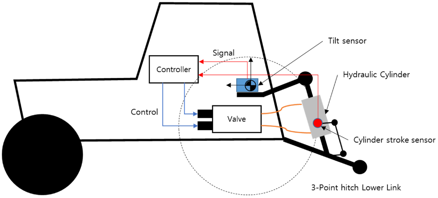
Leveling-control system layout.
Microelectromechanical systems (MEMS)-type acceleration sensors or electrolyte-type tilt sensors are used in the tilt sensors mounted on the tractors currently available in the market. In addition, the rolling angle of the tractor body can be accurately measured by machining the transmission surface as a flat surface on the rear differential case and installing it so as to form a 90° angle with the driving direction of the tractor.
The hydraulic cylinder is mounted on one of the lift rods present on both sides to control the implement angle, which transmits the lift of the three-point hitch lift arm and controls the implement attitude using the angle deviation between the tractor and implement caused by the varying length of the hydraulic cylinder. Herein, the cylinder length is detected using a cylinder-stroke sensor mounted on the side of a variable hydraulic cylinder.7,20,21 For the stroke sensor, a variable-resistance potentiometer was used to detect and estimate the variations in the cylinder length. This alters the motion generated by a particular variation of the cylinder length with respect to an electric signal, and subsequently, transmits it to the controller to estimate the variation of the cylinder length using the received signal. Based on the estimated variation of the cylinder length, the implement rolling angle is estimated using a trigonometric formula, assuming that the hitch is a static type. 5 However, the prior study did not consider the deviation in the estimated implement rolling angle from the actual value caused by the variations in the dimensions at major points of the hitch, as generated during the hitch operation.
The control algorithm of the conventional leveling system estimates the implement rolling angle required for leveling with the ground using the vehicle rolling angle measured with a tilt sensor. However, the estimated value of the required rolling angle of the implement has a sign opposite to that of the measured vehicle rolling angle. Moreover, the control algorithm varies the length of the horizontal cylinder by activating two on/off valves to ensure that the deviation between the absolute values of the required implement rolling angle and the measured vehicle rolling angle is within a certain dead zone. Thus, if the measured vehicle rolling angle is 5° and the dead zone of the system is 0.5°, the attitude of the implement is controlled within the range of −4.5 to −5.5 °. Thus, the sensor requires an accurate measurement as well as a rapid response to the variations in the vehicle rolling angle, because the vehicle rolling angle measured by the tilt sensor determines the overall performance of the implement leveling-control system. However, the current system exhibits an extremely slow response as it uses an electrolyte sensor, and the use of an acceleration sensor cannot assure accurate measurements of the angle in the case of an unexpected acceleration of the vehicle. 22
Initially, the hydraulic system branches a certain amount of flow from the hydraulic line of the tractor and supplies it to the horizontal cylinder for leveling-control. Thereafter, it supplies or stops the flow with the on/off valve. Thus, a branched priority flow is supplied, and the hydraulic cylinder operates at a constant speed when the controller operates the valve.
This study aims to accurately measure the attitudes of the implement and tractor to improve the performances of the hydraulic system and control algorithm with a follow-up study.
Implement rolling angle estimation algorithm
The three-point hitch of the tractor bears a link structure comprising a rear axle housing, lower link, lift rod, and lift arm. In addition, the position and motion of the link can be defined using certain constraints. Consequently, the three-point hitch of the tractor can be simplified and modeled as a closed loop with a four-section link, and the behavior of each link can be analyzed using the minimum information if the constraints are set for certain links.5,23 Thus, the mechanical behavior of this tractor three-point hitch was analyzed by modeling the angles between the links of the four-section link as shown in Figure 2.
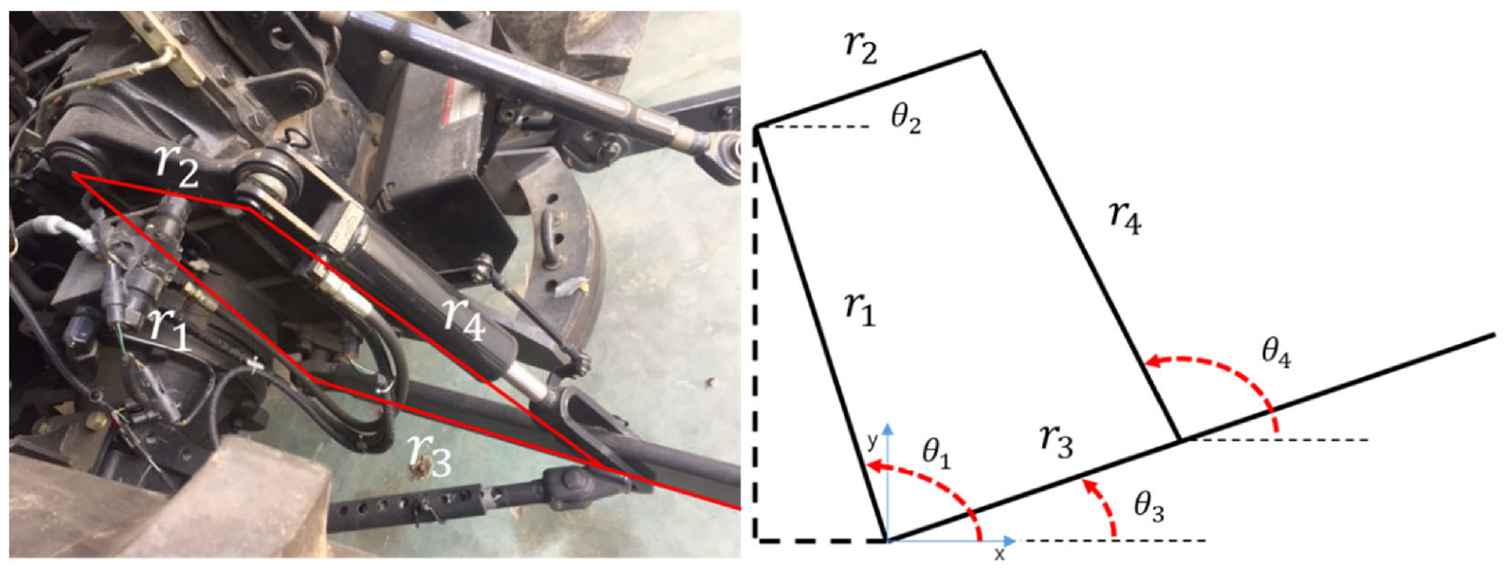
Modeling and schematization of angles between links.
The four-section link equation for the three-point hitch can be represented by the vector equation in equations (1) and (2), respectively. Herein, the hinge point coinciding with
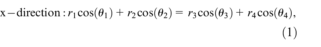

where
Equations (1) and (2) were simplified by expressing their parts in equations (3) and (4):


Upon substituting equations (3) and (4) into equations (1) and (2), the


Upon combining and rearranging both sides of equations (5) and (6), the following equation can be obtained:

To further simplify the equation, the left-hand side was replaced with

Equation (8) is a quadratic equation for

In addition, equation (9) is a quadratic equation as well, and

In particular, the implement height of the three-point of the tractor can be adjusted by altering the angle of the lift arm (
If the length of the lift rod

Variation between
The variation in the angles of the lower links on both sides,

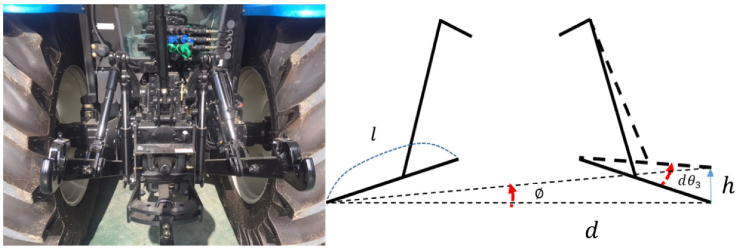
Modeling of implement rolling angle.
where
Consequently, the implement rolling angle Ø can be finally estimated using
Tilt angle estimation
The rolling angle of the tractor can be measured using the tilt sensor. Commercialized leveling-control systems utilize a sensor to measure the inclined angle through the electrolyte inside the sensor, including an acceleration sensor based on gravitational acceleration. 7 However, the accuracy of the tilt sensor is affected in case the acceleration of an axis varies from that of the rolling axis, such as in cases of pitching and yawing. In addition, the linear acceleration to the rolling axis or an acceleration caused by rotational motion affects the accuracy of tilt sensors, because it measures the slope using a component of gravitational acceleration. Therefore, the attitude of the tractor can be accurately predicted under dynamic conditions by developing an algorithm using the Kalman filter, which predicts the rolling angle of the tractor using gyroscopic and acceleration sensors. The block diagram of tilt angle estimation is shown in Figure 5.
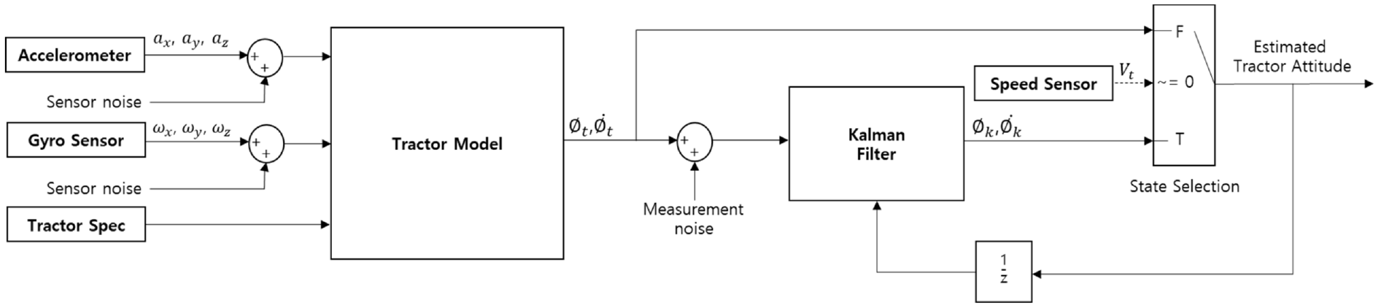
Block diagram of tilt angle estimation.
If the tractor is in a static state or driving at a constant forward velocity without any acceleration or deceleration, the accuracy can be adequately increased even if the attitude is measured using only an acceleration sensor because no deceleration or acceleration by turning occurs. Furthermore, when the tractor has stopped, the vibration caused by the engine rotation is dominant, and the noise component caused by the vibration can be reduced using only a simple low-pass filter (LPF). Thus, an accurate slope can be predicted using only the acceleration sensor information.
Therefore, the state of rest or constant-speed driving was determined as per equations (12) and (13) based on the vehicle speed and three-axis acceleration information of the tractor, and the tractor attitude at both rest and constant-speed driving states was determined using equation (14). Furthermore, for any state other than rest, the model could predict the attitude using the Kalman filter algorithm based on the dynamic model. As the coordinate axes, the roll and the longitudinal axis rotation of the tractor was defined as the x-axis, the pitch reflecting the lateral axis rotation was defined as the y-axis, and the yaw including the vertical axis rotation was defined as the z-axis. 24
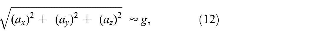


where
The dynamic state can be modeled instead of the rest or constant speed driving state by setting the rolling angle and its variation rate as the state variables:
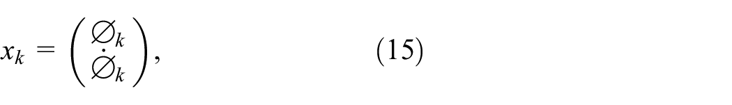
where
The equation of motion for the rolling angle of the tractor is expressed as equations (16) and (17), respectively.


The equation of motion for the rolling angle of the tractor is expressed as equations (18)–(20), from which the state transition matrix A and the system noise matrix W can be obtained as follows:


where


where
Regarding the acceleration sensor in a dynamic condition, the random acceleration in the axial direction, the acceleration caused by rotation, the component of gravitational acceleration according to attitude alterations, and the acceleration component caused by random driving of the tractor can be determined as follows:


where
Upon considering the working environment, the velocity of the tractor hardly existed in the z- and y-axis directions, and the variations in the pitch and rolling angles were approximately


Finally, the rolling angle

Among the components measured by the acceleration sensor, the component representing the actual angle is
The angular velocity measured by the angular velocity sensor was modeled as follows:

where
Consequently, all the components of equation (24) were assumed as adequately satisfying the linearity in a general working environment.
The measurement relational equations can be derived using equations (30) and (31) as follows:


where
The Kalman filter was applied using a system equation based on the above modeling to predict the rolling angle of the tractor.
The value of Q, which represents the system noise, was set based on the trial-and-error method, and it was modeled to be slightly smaller than R.25,26 The measured noise R was set based on the performance test data of the angular velocity along with the acceleration sensors used in the test. For the
Moreover, the initial rolling angle of the tractor was measured using the acceleration sensor, considering that the tractor started from a stationary condition. Furthermore, the initial angular velocity was assumed as 0, and the initial value of the covariance matrix was set to
Performance test
Equipment
This study used the XP7102 tractor, a mechanical front-wheel drive tractor manufactured by LSMtron (LSMtron Co., Gyeonggi-do, South Korea) that is equipped with Cat.2 hitch (ISO 730-1, ISO, 2009) 27 and a forward/backward electrohydraulic automatic transmission. The detailed specifications of this tractor are listed in Table 1.
Specifications of study tractor.

For the lift arm sensor predicting the implement attitude, a noncontact Hall type potentiometer sensor was used. As depicted in Figure 6, a link structure that can detect the rotation of the lift arm was installed to convert the rotation angle of the lift arm to an electric signal.

Lift arm sensor.
In addition, a variable–resistance-type potentiometer was installed in the stroke sensor mounted on the lift rod, and it was installed as a link structure to convert the cylinder length variation to an electric signal, as depicted in Figure 7.

Lift rod cylinder stroke sensor.
The sensor used for estimating the tractor attitude was mounted with separately fabricated brackets above the transmission housing in the same position as the conventional sensor. Subsequently, to compare its variations with the conventional system, certain tests were sequentially performed by attaching an electrolytic sensor, a MEMS-type accelerometer, gyroscopic sensor, and an accelerometer. The specifications of the sensors are listed in Table 2. In addition, a Hall sensor was mounted to measure the rotational speed of the final output gear of the rear axle, which was converted to a vehicle velocity. Thereafter, the results were received through the controller area network (CAN) communication.
Specifications of study sensors.

Infineon’s XC2387A microprocessor was used as the controller to measure the sensor values and drive the valves, and its detailed specifications are listed in Table 3.
Specifications of microprocessor.

For the analog voltage input, the voltage signal input measured from the microprocessor was converted to a 10-bit digital signal and transmitted through the CAN communication, which is frequently used for vehicle communication. The sampling rate was set to 100 Hz.
Test method
The estimation accuracy of the implement rolling angle was evaluated by varying the angle of the three-point hitch lift arm (
Main dimensions of three-point hitch and implement of tractor used in the test.

A commercial tilt sensor was mounted above the implement to measure the actual rolling angle of the implement, as shown in Figure 8 and the detailed specifications of the sensors used in this test are listed in Table 5.

Tilt sensor mounted above the implement.
Specifications of tilt sensor.

The angle of the three-point hitch lift arm was measured using a lift arm sensor mounted on the three-point hitch. The 60° range constituting the full-stroke range of the three-point hitch was divided into intervals of 12°. Thereafter, the actual rolling angle of the implement was measured upon continuously varying the length of the lift rod (
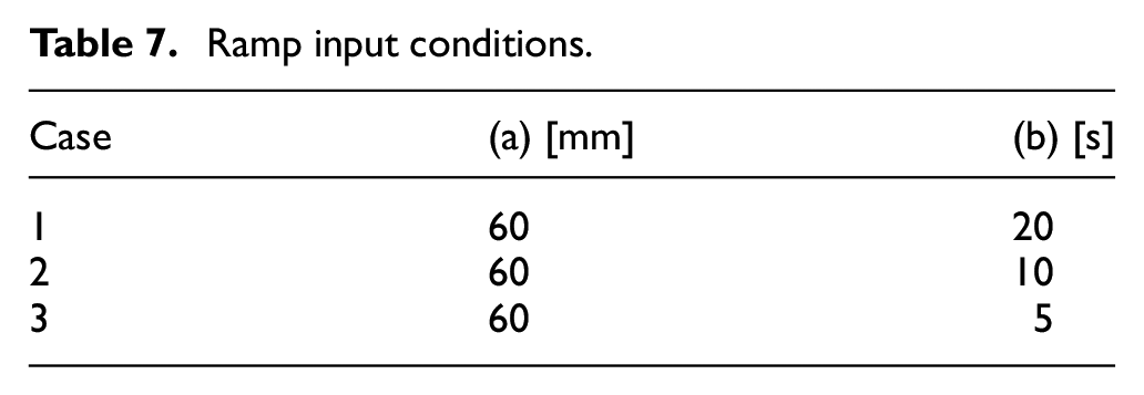
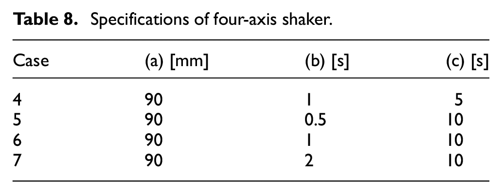
Furthermore, a four-axis shaker was used to evaluate the performance of the implement leveling-control system, as shown in Figure 9. Using the improved algorithm, upon inclining the tractor, the horizontal attitude control performance of the actual implement was compared for the conventional system and the improved algorithm with the same reference input. Regarding the reference waveforms, a sine-wave input with an altered frequency and a ramp input with an adjusted slope were applied. For the sine-wave input, a 180° phase difference for the left- and right-hand side wheels was achieved to generate lateral rolling. Thereafter, a maximum amplitude of 120 mm was achieved by applying the frequencies of.05, 0.1, and 0.2 Hz based on an amplitude of 60 mm. Consequently, the vehicle was tilted up to 4.51°. For the ramp input, the input displacement of one wheel was +90 to −90 mm, and the rolling angle speed was varied by controlling the ascent and descent periods of the ramp. The sine-wave reference input waveforms are presented in Figure 10 and Table 6, and the ramp input waveforms are portrayed in Figure 11 and Table 7. Overall, the maximum amplitude was derived using the maximum and minimum implement rolling angles when the leveling control was realized using both the conventional and the improved system. Moreover, the peak value was calculated to compare the damping ratio of the maximum amplitude of the implement rolling angle with the maximum input amplitude. The max function method was employed for the waveform value over time. In addition, leveling control was performed according to the reference input to compare the implement leveling-control accuracy. Furthermore, the RMSE of the implement rolling angle was determined for sea level (rolling angle = 0°) during the entire test period and compared between the conventional system and the improved system. The specifications of the four-axis shaker used in this study are detailed in Table 8.

Test tractor mounted on a four-axis shaker.

Input characteristics of the sine wave.

Ramp input waveform.
Sine wave input conditions.

Ramp input conditions.
Specifications of four-axis shaker.
Results and discussion
Verification result of implement estimation algorithm
Figures 12 and 13 present the results of varying the range of motion of the three-point hitch, 60°, in intervals of 12°. Figure 12 depicts the result when the length of the lift rod (

Comparison of the results of the estimated angle between the proposed and conventional algorithms according to the hitch variation: (a) Hitch 0°, (b) Hitch 12°, (c) Hitch 24°, (d) Hitch 36°, (e) Hitch 48°, and (f) Hitch 60°.

RMSE comparison of the estimated angle between the proposed and conventional algorithms by hitch angle variation.
Result of leveling-control performance improvement test
Figures 14 and 15 display the measurements of the implement rolling angle with sine wave and ramp inputs in the conventional and proposed leveling systems. Figure 14 depicts the results of frequency variations based on the amplitude of 60 mm in the sine wave, wherein Figure 14(a) portrays the results of inputting a frequency of 0.05 Hz with the same amplitude of 60 mm in the sine waveform. The RMSE of the conventional system rolling angle (conventional) was 0.95°, whereas that of the proposed system rolling angle (proposed) was 0.37°. In addition, the RMSE of the proposed system was 61.05% less than that of the conventional system. For accurate verification, the rolling angles were measured by varying the frequency to 0.1 and 0.2 Hz. The results revealed that the RMSEs of the rolling angle were 1.79° and 2.79° in the conventional system, whereas those in the proposed system were 0.49° and 0.84°. Thus, the RMSEs of the proposed system for the frequencies of 0.05, 0.1, and 0.2 Hz were 61.05%, 72.63%, and 69.89% less than those of the conventional system, respectively. Moreover, Figure 15 presents the results of varying the straight and inclined angles based on an amplitude of 90 mm in the ramp input, wherein Figure 15(a) depicts the results of inputting 5 s for the straight angle and 1 s for the inclined angle under the same conditions. In particular, the RMSE of the rolling angle was 1.46° in the conventional system, whereas that of the proposed system was 0.39°. Thus, the RMSE in the proposed system roll was 73.29% less than that of the conventional system roll. Moreover, Figure 15(b) to (d) present the results of varying the inclined angle based on the straight angle for 10 s. Sequentially, the inputs were 0.5, 1, and 2 s, for which the RMSEs of the rolling angle were 1.44°, 1.16°, and 0.85° in the conventional system, whereas those in the proposed system were 0.79°, 0.32°, and 0.37°, respectively. Thus, the RMSEs of the proposed system were 45.14%, 72.41%, and 56.47% less than those of the conventional system, respectively. Therefore, the RMSEs of the proposed system were more proximate to 0° than those of the conventional system, which indicated that the system performance was improved. It means that implement tilt angle estimation using gyroscopic and acceleration sensor can reduce time delay and estimation error than using acceleration sensor only or electrolyte-type sensor. Moreover, Kalman filter and estimation algorithm can reduce measurement error from disturbance of unexpected tractor acceleration and vibrations. However, the peaks burst because the hydraulic reactive speed of the system could not satisfy the reactive speed of the cylinder. In case the on/off control method was used during feedback control, a delay occurred when the system was switched on or off, and there was a variation in the reactivity of the on and off speeds. Nonetheless, this problem can be solved if the error rate is reduced by repeatedly modifying the settings of the operation signals in the subsequent test.

Implement rolling angle according to sine wave: (a) Case 1, (b) Case 2, and (c) Case 3.

Implement rolling angle according to ramp input: (a) Case 4, (b) Case 5, (c) Case 6, and (d) Case 7.
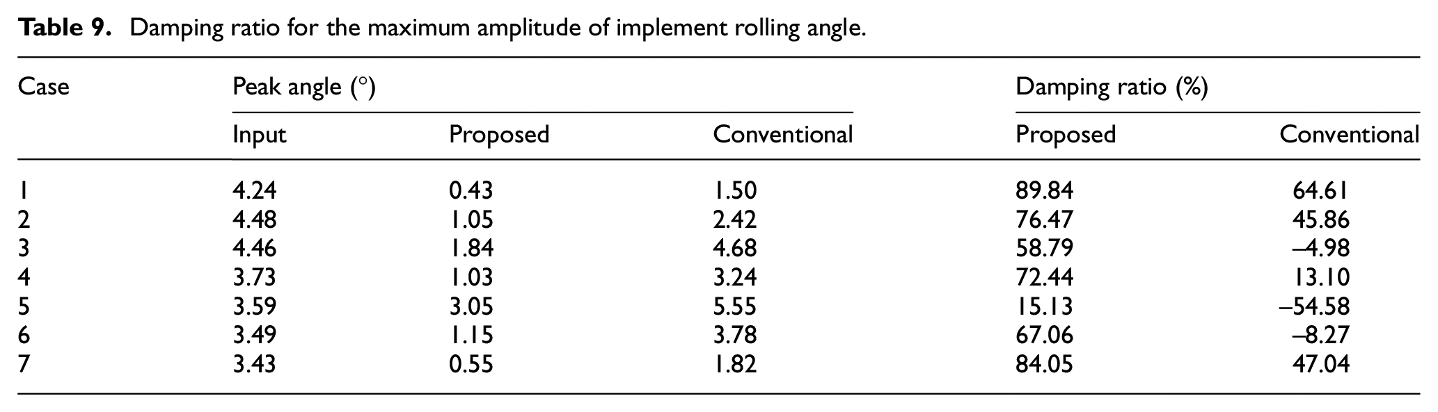
The damping ratios of the maximum amplitude of the implement rolling angle to those of the input rolling angle measured using the output value are listed in Table 9, which shows that the proposed system exhibited a larger damping ratio for the maximum amplitude of the input rolling angle than the conventional system under all test conditions. Moreover, a negative damping ratio of the conventional system indicates that the output vibration is larger than the input vibration. In the conventional system, the accuracy of the rolling angle estimation algorithm is low, and the measurement delay of the sensor is very large; therefore, it cannot match the speed of the tractor tilting, and the error in one direction is thus amplified.
Damping ratio for the maximum amplitude of implement rolling angle.
Summary and conclusions
This study proposed a control algorithm using gyroscopic and acceleration sensors to improve the precision and speed of the conventional tractor–implement leveling-control system. The improved performance of the proposed system was verified by comparing the conventional and improved systems. The major results of this study are summarized as follows:
The measured value of the implement rolling angle according to the variation in the hitch and the estimated values of the implement rolling angle in both the conventional and the improved systems were analyzed. The deviation between the estimated and measured values for the entire stroke of the lift-rod cylinder were represented with RMSEs by varying the rod length. At 0° hitch, the RMSE of the estimated value of the conventional system was 0.44°, whereas that of the estimated value of the proposed system was 0.02°. Thus, the RMSE of the proposed system was 95.45% less than that of the conventional system. Additional tests revealed that the RMSEs of the proposed system at 12°, 24°, 36°,and 48°, and 60° were 86.05%, 80.77%, 79.66%, 78.33%, and 84.00% less than those of the conventional system, respectively. This proved the higher modeling accuracy of the improved system in comparison to that of the conventional system.
In addition, a vehicle was placed on a four-axis shaker and subsequently inclined to evaluate the performance of the implement leveling-control system. Consequently, the results of the sine-wave and ramp inputs were compared. For the sine-wave input, the frequency was varied with the amplitude fixed at 60° in the sine waveform. In particular, the RMSEs of the conventional system rolling angles were 0.95°, 1.79°, and 2.79°, whereas those for the proposed system rolling angle were 0.37°, 0.49°, and 0.84° for the frequencies of 0.05, 0.1, and 0.2 Hz, respectively. Thus, the error rates of the proposed system were 61.05%, 72.63%, and 69.89% less than those of the conventional system.
Moreover, the straight and the inclined angles were varied while maintaining the amplitude of the ramp at 90°. In the case of 5 s for a straight line and 1 s for an inclined line, the RMSE of the conventional system rolling angle was 1.46°, whereas that of the proposed system rolling angle was 0.39°. Thus, the error decreased by 73.29% compared to that of the conventional system. In cases of 0.5, 1, and 2 s based on a straight 10 s, the RMSEs of the conventional system rolling angle were 1.44°, 1.16°, and 0.85°, whereas the RMSEs of the proposed system rolling angle were 0.79°, 0.32°, and 0.37°, respectively. Thus, the error decreased by 45.14%, 72.41%, and 56.47% compared to that of the conventional system. This suggested that the control performance of the implement leveling-control system could be improved by reducing the implement attitude estimation error.
In order to improve the performance of implement leveling control system, nonlinearity of tractor and implement dynamic system, proportional controllable hydraulic system and high dimensional tractor model were considered. In this study, we have conducted a basic study to improve performance of implement leveling system, and we will propose additional studies that apply the nonlinear estimation model, high dimensional tractor dynamic model and proportional hydraulic flow control valve for variable speed control of lift rod cylinder.
Footnotes
Handling Editor: Chenhui Liang
Declaration of conflicting interests
The author(s) declared no potential conflicts of interest with respect to the research, authorship, and/or publication of this article.
Funding
The author(s) disclosed receipt of the following financial support for the research, authorship, and/or publication of this article: This study has been conducted with the support of the Korea Institute of Industrial Technology as “Research equipment coordination project (kitech JA-22-0004).”