
Abstract
This paper focuses on finite element (FE) modeling using a Lagrangian approach with the ABAQUS/Explicit code to simulate the morphology of CSN 12050 carbon steel chips obtained using different tool rake and flank angles. The cutting operation was performed with a 3D model setup based on the cutting tool to determine the impact of the tool rake and flank angles on the total energy (ETOTAL), the von Mises stresses, and the cutting force. In these simulations, using adaptive meshing for the tool, 0°, 5° and 10° rake angles, 0° and 6° flank angles, and 0.2-mm and 0.5-mm cut depths were considered as process parameters and the continuous chip morphology was predicted. The tool with 10° rake and 6° flank angles projected moderate machined surface integrity. The FE analysis tool predicted increased von Mises stresses and reduced cutting forces with the 10° rake and 6° flank angles. The maximum ETOTAL and cutting force were obtained for both cut depths when using a tool with 0° and 5° angles. Additionally, experimental results for the mechanical morphology properties of untreated, annealed and recrystallized CSN 12050 carbon steel chips showed that the predicted and experimental chip morphologies agreed well.
Keywords
Introduction
Chip morphology analysis is useful for prediction of an efficient chip removal process through consideration of both a safe and favorable working environment and process simplification. Numerous mathematical models have been developed based on an orthogonal cutting model to simplify the required assumptions. Among the numerous metal cutting theories available, the most popular was the Merchant theory. 1 Finite element modeling-based simulations of turning processes have since provided better understanding of the chip morphology and the stress components. Numerical analysis of the orthogonal cutting process, computer simulations of material separation processes, the influence of various tool configurations on the turning finish, and numerical and experimental studies of dry cutting have been reported.2–4 There have been many related studies of machining, chip formation and chip morphology. Several of the numerical simulation-based studies of machining are discussed in the following. Using the available experimental results, simulations of cutting of low carbon steel were performed and the results were compared with experimental results obtained under similar cutting conditions. The simulation results were found to agree well with the experimental results. 5 Oblique and orthogonal cutting operations were modelled and simulated using DEFORM 3D software. The simulated results were compared with the experimental results and showed good agreement when predicting chip flow during cutting processes. 6 The robustness of the results was examined to determine the sensitivity of the simulations to detailed changes in flow development using the iterative convergence method (ICM). The simulated results from a finite element analysis were then compared with experimental results. 7
In a similar manner, sensitivity analyses were performed on different frictional coefficients through simulations and the results were compared to explain the effects of flow stress and friction on the predictions. 8 An experimental validation of the cutting process was conducted that verified the simulated results on stainless steel (American Iron and Steel Institute (AISI) 316) and the comparison showed that the friction modelled at the tool-chip interface had a significant influence on the final results.9,10 Using tungsten carbide tooling, experiments on and simulations of machining of AISI 4340 steel were also performed. The tool–chip contact friction was studied and the validity of the friction modelling approach was examined to determine the influence of the limiting shear stress. The results were presented to aid in understanding of the friction effect in finite element (FE) analysis of machining. The modified material model for Inconel 718 was compared with the corresponding Johnson–Cook model. The modified material model demonstrated improved predictions of the forces involved and of chip formation.11,12
Another simulation model focused on FE simulation of orthogonal machining processes on different materials to obtain the magnitude and the direction of the residual stress induced in each workpiece. The Johnson–Cook material model was used to describe the working material’s behavior. A fully coupled thermomechanical analysis was developed to simulate the machining process realistically. A graphical analysis of the residual stress versus the machining parameters was performed, and decisions were made based on this analysis about selection of the optimum machining process to improve component lifetimes. 13
The effectiveness of the current numerical predictive models for determination of machining performance was also evaluated. Five representative working materials were selected carefully for this study from a range of the most commonly used working materials, along with a wide range of cutting conditions. The differences between the predicted results obtained from the various numerical models when using different FE and mesh-free codes were evaluated and were then compared with experimentally obtained results. 14 Machining simulations are challenging with respect to both numerical issues and the physical phenomena that occur during machining processes. The latter issue is mainly related to the description of the bulk material’s behavior (plasticity) and its surface properties (friction and wear). The predictive models available at present, depending on their scopes, were also assessed to determine the developments required for their future use. The mechanisms of chip formation during cutting operations were observed both experimentally and through numerical simulations. In the experiments, the chip morphologies were characterized and the microstructures of the chips under high loading conditions were investigated. The effect of the cutting conditions on the cutting forces was also assessed. Therefore, the chip segmentation phenomenon was correlated with the evolution of the cutting forces. Numerical simulations dealt with chip formation and also considered thermomechanical phenomena. Several numerical results related to chip formation based on the theory of strain gradient plasticity were also discussed. The advantages of arbitrary Lagrangian Eulerian (ALE) and Lagrangian formalisms for simulation of continuous-type processes were also discussed. Through a highly complex industrial application, the ease of use of ALE modelling with the researchers’ own in-house METAFOR code was also illustrated. The ALE and Lagrangian results showed good agreement with each other.15–17
Finite element method (FEM) simulations of orthogonal turning processes were performed based on the Lagrangian formulation using ABAQUS/Explicit software along with the Johnson–Cook plasticity model.18,19 The Johnson–Cook damage law for the chip separation criterion was also applied.
20
Cutting tool materials were developed with different geometries for their rake and flank angles. These different tool geometries have been used to investigate the effects of tool rake and flank angles on prediction of the chip morphology, the total energy (ETOTAL), the stress fields on the machined surface and the cutting force. In turning investigations, most research attention has been paid to modeling of the effects of the cutting speed and the feed rate on the tool geometry using geometrically simple orthogonal cutting processes and plastic deformation.21–26 Three-dimensional FE simulations of the cutting forces and the cutting temperature during hard milling of AISI H13 steel have also been performed.
27
The known tool geometries involved in orthogonal cutting are the rake angle and the clearance angle. The rake angle
Recently, research has been performed on the evolution of the chip morphology, chip formation and the surface topography with respect to the cutting parameters, along with the relationships between these factors during dry milling of cast aluminum alloy using a polycrystalline diamond (PCD) inserter. 28 A new geometric model of serrated chip formation during high speed machining 29 and an accurate transient model of temperature fluctuations on the localized shear band in serrated chip formation have also been proposed. 30 Using coordinate measuring machines (CMMs), a digital tooth contact analysis of face gear drives was performed with an accurate measurement model of the face gear tooth surface; 31 an innovative geometric error compensation method for multi-axis computer numerical control (CNC) machine tools with nonrotary cutters for accurate worm grinding of spur face gears was also proposed. 32
Model formulation
Because of a combination of computational efficiency, easy tracking of the material boundaries, and ease of implementation in metal cutting models, most of the previous researchers have used the Lagrangian formulation for their models.21–23 For metal cutting simulations, the Lagrangian formulation is preferable because it enables more convenient modeling of the evolution of the chip from its incipient stage to the steady form. 3 In this work, the Lagrangian approach was selected and a 3D geometric orthogonal turning model of CSN 12050 carbon steel was used during the FEM modeling and simulation. The Lagrangian formulation can allow simulation of the chip morphology without definition of the initial chip shape from the incipient state to the steady state. This formulation also gives more realistic results when predicting the chip morphology and other machining-related phenomena and parameters, including stress, ETOTAL and the cutting force. The material model selected in this work was the Johnson–Cook plasticity model, and for the chip separation criterion, the Johnson–Cook damage law was used.
FEM 3D geometric model, meshing and boundary conditions
FE analysis of the chip morphology, ETOTAL, the component stress fields and the cutting force during orthogonal cutting of CSN 12050 carbon steel with a carbide cutting tool was performed. The geometry of the problem domain was developed by reducing the complexity of the actual geometry to allow the problem to be solved and analyzed efficiently, and also to allow accurate results to be attained from the FEM analysis when using different cutting tool geometries in terms of the rake and flank angles. The values are selected with consideration of the mesh density and by using the failure model proposed based on the Johnson–Cook method for chip separation. 20 The cutting conditions were selected for continuous chip formation. The effects of the cutting tool geometries of the rake and flank angles on the chip morphology and the components of the stress fields were studied. The 3D model consists of a hexahedron region (Hex), which is used in place of the workpiece and the cutting tool. In the modeled orthogonal cutting tool, the geometrical angles consist of the rake angle (α = 0°, 5° and 10°), the flank angle (γ = 0° and 6°), and the inclination angle (λ = 90°). Figure 1 shows the intermediate region of an element in which the damage zone is indicated with an arrow. From the orthogonal model’s perspective, the width of the upper surface in the Y-plane is equivalent to the feed width and is basically equal to the uncut chip thickness.

3D finite element model of orthogonal cutting process with dynamic explicit displacement boundary conditions.
The boundary conditions for the bottom of the 3D geometric model workpiece are fixed in the Y-direction and support calculation of the feed force during the turning process. Similarly, the vertical edge of the workpiece on the left side is fixed in the X-direction and supports calculation of the cutting force during the turning process. The cutting velocity of the tool is required in the negative X-direction and the tool’s top edge is constrained in the vertical direction, as indicated in Fig. 2. The field output variables, the plotted contours on the deformed area and the undeformed 3D geometric shape from the FEM model module are shown in Fig. 2. As Fig. 2 illustrates, the components of the reaction force added at all the constrained nodes on the left vertical edge of the workpiece in the X-direction provided the cutting force, while the bottom edge of the workpiece in the Y-direction provided the feed force.
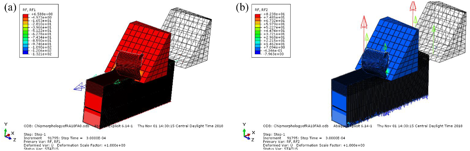
FEM model module field output variables, where (a) the reaction force in the X-direction provides the cutting force and (b) the bottom edge of the workpiece reaction force in the Y-direction provides the feed force.
As shown in Fig. 1, the damage zone and the undeformed chip thickness (to) are used to specify the path of separation between the chip surface and the machined surface. In the model presented here, both the workpiece and the cutting tool use eight-node linear brick (C3D8R) elements with a reduced integration scheme and hourglass control for the discretization. The workpiece and cutter were meshed using C3D8R-type elements by performing an unstructured grid generation that made use of the advancing front algorithm in ABAQUS/Explicit. Constant friction of µ = 0.3 was applied between the modeled workpiece and the tool materials using the penalty surface contact method.
Dynamic explicit solution
The machining analysis consists of complex contact problems; as a result, an implicit algorithm will be less efficient in providing simultaneous solutions for the equation system at every increment. Therefore, we use the explicit dynamic Lagrangian approach, which is suitable for solution of nonlinear problems that involve large deformations and changing contact conditions. The explicit dynamic procedure available in ABAQUS/Explicit is based on implementation of an explicit integration scheme. The explicit formulation produces the solution more rapidly when compared with the central difference method, 3 and can be given as equation (1).

where
The principle of the explicit FEM consists of Newton’s second law being rewritten into matrix form and defined at the beginning of each step as shown in equation (2). 3
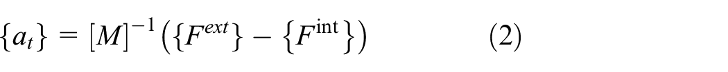
where {at} is the vector of the acceleration in time t, [M] is the mass matrix, {Fext} is the vector of the external forces applied in time t, and {Fint} is the vector of the internal forces applied in time t.
The most important advantages of the explicit FEM are that simple code is used, building of the stiffness matrix (
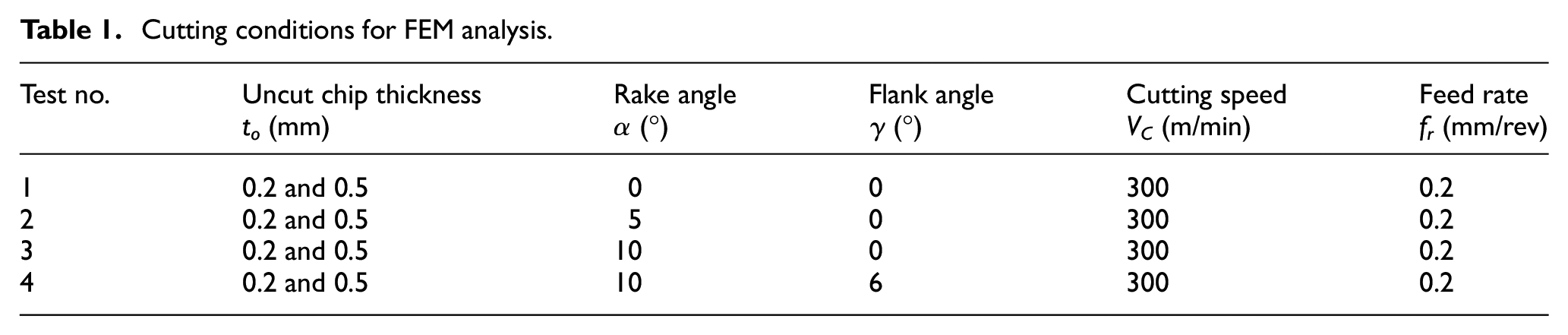
Cutting conditions for FEM analysis.
Constitutive material modelling of CSN 12050 carbon steel materials
In the FE analysis (FEA), accurate flow stress models were considered to represent the workpiece material’s constitutive behavior under high-strain-rate deformation conditions. The thermo-mechanical properties of a material undergoing deformation can be described and modeled using the constitutive equations. The constitutive equations of plasticity deal with the yield criterion, the flow rule, and the strain hardening rule. The Johnson–Cook (JC) hardening method constitutive equation is a model that describes the flow stress behavior of workpiece materials using the product of strain, the strain rate and temperature effects.18,20 In this paper, by incorporating the results of an experimental investigation of the mechanical properties of CSN 12050 carbon steel with the JC hardening method, the constants for the constitutive equation were determined as shown in Table 2. The formula used to solve for n yields is shown in equation (3). 28


Here, n and K are constants; in this research work, the value of K is assumed to be 1035 MPa.
A: initial yield stress; B: hardening modulus; n: work-hardening exponent; c: strain rate-dependent coefficient; m: thermal softening coefficient.
In this study, a rate–dependent JC constitutive equation was preferred and was used to investigate the effects of the tool rake and flank angles on the chip morphology, ETOTAL and the components of the stress fields for the CSN 12050 carbon steel materials.

where
In the simulation work, the carbide cutting tool was modelled as an elastic material, whereas the workpiece material was defined as an elasto-plastic material. The thermomechanical properties of the carbide cutting tool and the CSN 12050 carbon steel material are given in Table 3.

Damage initiation
The requirements for the damage model include a material response (for the undamaged material), a damage initiation criterion, the damage evolution and a process for selection of element deletion. The material state at the onset of damage represents an implication of the damage initiation criterion. In this study, the JC damage initiation criterion was used. The damage parameter

where Δ

where d1 is the initial failure strain, d2 is the exponential factor, d3 is the triaxiality factor, d4 is the strain rate factor, and d5 is the temperature factor;

Damage evolution
Because of the use of progressive damage, damage initiation was followed by a damage evolution criterion that governs the propagation of the damage until ultimate failure occurs. When the element fulfills the damage initiation criterion, progressive degradation of the material stiffness is expected to occur, causing the material to be disposed to failure based on the damage evolution. During analysis of the strength of the material within the required analysis time, the stress tensor in the material can be calculated using equation (7):20,33

where
Element deletion requirement in ABAQUS 6.14 with the explicit model
The yield stress, the equivalent plastic strain at the beginning of the damage, and the equivalent plastic strain at failure are considered; deletion is performed when the overall damage variable reaches the value of D = 1. Then, the element concerned is removed from the computation (when D = 1) at every integration point using the element deletion technique provided by the ABAQUS 6.14 software. 19 Element deletion can be achieved throughout the module, along with the JC damage model; 19 therefore, the software enables deletion of the elements that fail. This then produces the chip separation and allows the cutting tool to penetrate further into the workpiece along a predefined path (the damage zone). A dilatation of the element is based on the value of the equivalent plastic strain at the element integration points.
FE 3D geometrical model simulations for CSN 12050 carbon steel
The model proposed in this paper uses the ABAQUS/Explicit version 6.14-1 software 19 to realize the turning process simulation results. The 3D geometrical model was provided with dimensions of 10 mm in length and 3.5 mm in height, and the height of the conditional link element is 2.5 μm. The resulting meshes for 0°×0°, 5°×0°, 10°×0° and 10°×6° (representing the rake and flank angles, respectively) were built from 9384 nodes and 4560 elements, 9696 nodes and 4688 elements, 9696 nodes and 4688 elements, and 9534 nodes and 4568 elements, respectively. In this simulation work, an adaptive meshing approach is used because the metal cutting process is an extremely dynamic experience and involves substantial changes in geometry. Example 3D model simulation results obtained for the chip morphologies when using the different tool rake and flank angles (0°, 5° and 10° rake angles with 0° and 6° flank angles) are illustrated in Fig. 3 for the 0° and 0° case.

Test 1: CSN 12050 carbon steel chip morphology obtained using a tool with 0° rake and 0° flank angles and a 0.5-mm depth of cut.
The FEM simulation results for the chip morphology obtained above using the different depths of cut and rake/flank angles demonstrate how easily the impact of the depth of cut and the tool rake/flank angles can be understood. From the required chip morphology simulation results, the optimum tool rake/flank angles and optimum depth of cut were determined to be the 10° rake/6° flank angles and a 0.2-mm depth of cut. The chip morphologies that were shown during FEM simulations with the optimum tool rake/flank angles and optimum depth of cut using the untreated, annealed and recrystallized CSN 12050 carbon steel materials were the same in terms of their shape. However, their results for ETOTAL, von Mises stress and the cutting force were different. The experimental results for the chip morphology and the FEA simulation results for ETOTAL, the von Mises stress and the cutting force for untreated CSN 12050 carbon steel are discussed below. In addition, a comparison of the experimental results for the mechanical properties of untreated, annealed and recrystallized CSN 12050 carbon steel with the corresponding FEA simulation results is also presented.
Experimental test results for chip morphology of CSN 12050 carbon steel workpiece material
A comparison of the chip morphology that was obtained from the output of the FEM simulation with the chip morphology obtained through experimentation is required to verify the correlation between the results attained for the chip morphology. Therefore, a CNC center lathe and the carbide cutting tool were used to perform the turning operation using a constant 0.25 mm/rev feed rate and a constant 275 m/min cutting speed with different tool rake/flank angles and depths of cut. The experimental dry turning results for the chip morphology are shown in Fig. 4.
Experimental dry turning test results for the chip morphology of CSN 12050 carbon steel workpiece materials with different depths of cut (1.0 mm and 1.5 mm) and tool rake/flank angles.
The results for the chip morphology when using different rake/flank angles and depths of cut confirmed the similarity of the FEM simulation output chip morphology to the experimental results obtained through the turning process that are shown in Fig. 4.
Results and discussion
Using the 3D model composed of the hexahedron region, FEM simulations were conducted for the required tests, numbered 1 to 8, under orthogonal turning conditions using the proposed Lagrangian approach. The 3D model represents the workpiece and the portion of the cutting tool that participates in the cutting process alone. The extent of the deformation that the workpiece material undergoes determines the nature or type of the chip that is produced and the type of chip morphology. However, the main focus of this study is to evaluate the influence of the tool geometry on the chip morphology, the total energy output sets, the stress field and the cutting force through the FEM analysis.
Influence of rake/flank angle and depth of cut on the chip morphology
The different process conditions used in the FEM simulations of tests 1 to 8 led to different forms of the continuous chip morphologies being obtained. The simulation results from test 1 using the 0.5-mm depth of cut showed an erect but slightly curved chip morphology. This was predicted for use of a cutting tool with 0° rake and 0° flank angles, and with plastic deformation of the material without fracture ahead of the cutting edge of the tool. The simulation results from test 2 when using the 0.5-mm depth of cut with a tool with 5° rake and 0° flank angles showed a moderately curved chip morphology.
Furthermore, the simulation results obtained in tests 3 and 4, when using the 0.5-mm depth of cut and the 10° rake and 0° and 6° flank angles, showed a continuous chip morphology in a coiled shape form. Conversely, with the exception of the tool with the 0° rake and flank angles, the results for the remaining tools with the 5° and 10° rake angles and 0° and 6° flank angles showed predictions of substantial changes in the continuous chip morphology when using the 0.2-mm depth of cut. Additionally, when the tool with the 10° rake and 6° flank angles was used, a considerable change to a smoothly coiled shape for the chip morphology with a moderate machined surface integrity was predicted for test 8.
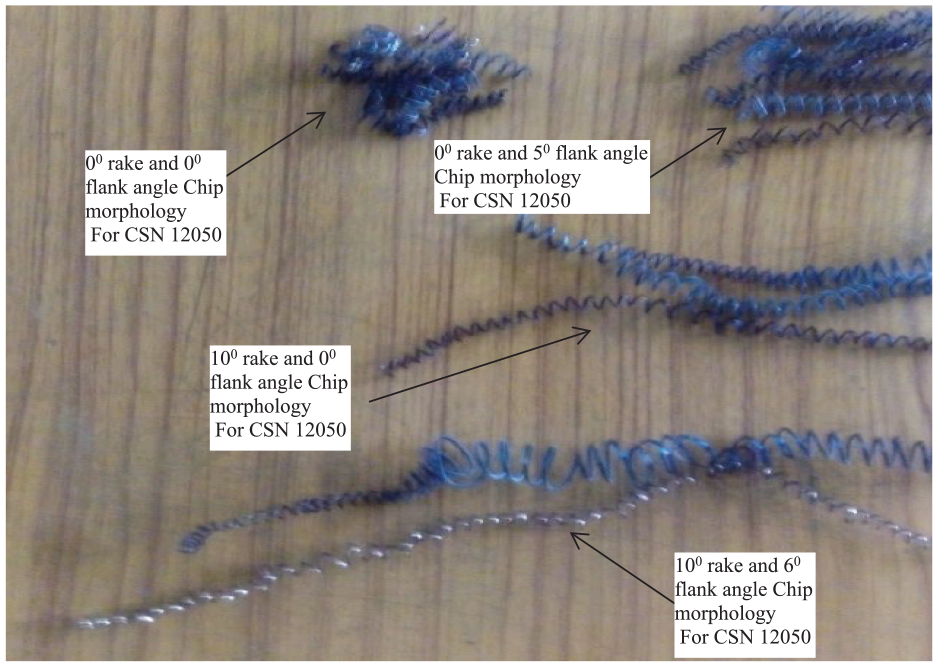
Therefore, from the chip morphology simulation results presented above, one can easily predict the extent of the effects of the tool rake and flank angles on ETOTAL, the stress fields on the machined surface and the cutting force. The chip morphologies that were obtained experimentally showed good agreement with the FEM modeled and simulated results. Figure 5 shows the effects of the depth of cut and the tool geometries on the chip morphologies obtained during the experimental turning of the untreated CSN 12050 carbon steel workpiece material. From the experimental results, a separated continuous chip morphology with a small length form and a heat-affected darker tan color for the untreated CSN 12050 carbon steel were shown to occur when using the 0° and 5° rake angles and the 0° flank angle in the cases of both 1-mm and 1.5-mm depths of cut. In contrast, the chip morphology obtained for the 10° rake angle and the 0° and 6° flank angles showed a continuous morphology with a moderate machined surface integrity. However, the effect of the depth of cut was shown when using the 1.5-mm depth in the heat-affected darker tan color chip morphology obtained when using the 10° rake and 0° and 6° flank angles. A very smooth and shiny chip morphology result was achieved experimentally for the 10° rake angle and the 6° flank angle in particular when using the 1.0-mm depth of cut.
Effects of various tool geometries (rake and flank angles) on the chip morphology and the total energy value for untreated CSN 12050 carbon steel material when using the 0.2-mm depth of cut.
Influence of rake/flank angle and depth of cut on the total energy output set
The energy state from the FEM simulation results provided good evidence of the effect of excessive heat on the chip morphology, which was predicted for the turning processes at different cutting tool rake and flank angles (0°, 5° and 10° rake angles with the 0° flank angle, and the 10° rake and 6° flank angles).
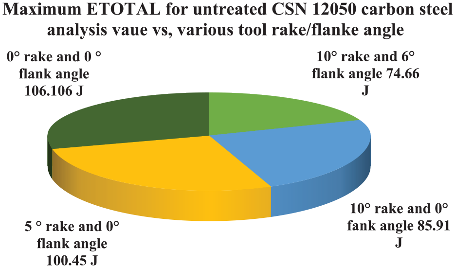
In this study, the FEM simulation results are used to predict the total energy output set relative to time. The substantial influence of the tool rake and flank angles on the energy/power consumption of the turning process can be understood from these predictions. As shown in Fig. 6, the chip morphology provides significant information about the total energy output sets for the cases of 0° rake and flank angles, 5° rake and 0° flank angles, 10° rake and 0° flank angles, and 10° rake and 6° flank angles for the entire model in terms of energy vs. time characteristics. It is clear that from the FEM simulation predictions, the maximum total energy output set occurs in the 0° rake and flank angles case when using untreated CSN 12050 carbon steel, as shown in Fig. 5.

Maximum von Mises stress values obtained when using various tool geometries (rake/flank angles) along with the required 0.5-mm depth of cut from the turning simulation results.
A simulation was performed with gradually increasing total energy to demonstrate the influence of the rake and flank angles on the output chip morphology, as shown in Fig. 7. Finally, when different tool geometries (i.e., rake and flank angles) are used along with the required depth of cut, a substantial influence on the results for the chip morphology and ETOTAL can be observed for the untreated CSN 12050 carbon steel.
Influence of rake and flank angles on stress fields when using untreated CSN 12050 carbon steel material
A simulation with various von Mises stress values was performed to demonstrate the influence of the rake and flank angles on the machined surface from the following field data: S: Mises at part instance part 1-1 element 1229 integration point. The maximum values of the von Mises stress were 579.90, 607.79, 629.58 and 703.01 MPa when using tools with rake and flank angles of 0°× 0°, 5°× 0°, 10°× 0°, and 10°× 6°, respectively, with the 0.5-mm depth of cut. From the FEM simulation predictions, the associated yield stress of the von Mises effective stress at the part instance part 1-1 element 1229 integration point showed a maximum value when using the tool with the 10° rake and 6° flank angles. The maximum values for the von Mises stress were determined successfully in the turning simulation in the cases where the 0.5-mm and 0.2-mm depths of cut were required, as shown in Figs. 6 and 7.

Maximum von Mises stress values obtained when using various tool geometries (rake and flank angles) along with the required 0.2-mm depth of cut.
Effect of tool rake/flank angles on cutting force using untreated CSN 12050 carbon steel material
The results obtained from the FEM chip morphology simulations listed in Table 5 show that the tool rake angle had a significant effect on the cutting force. The cutting tool can pierce into the workpiece material easily because a more positive rake angle produces a higher shear angle, and it therefore helps to reduce the cutting force. Similarly, the chip flows more easily and lower plastic deformation work is also required when using a cutting tool with an increased rake angle. In the FEA simulations, the extent of the cutting force reduction was most evident as the rake angle increased from 0° to 10° and the reduced depth of cut (0.2 mm) was used. From the simulation analysis results, it was observed that when the tool rake angle increased, the cutting force decreased, and the force then increased when the tool rake angle decreased, as shown in Table 5. An increase in the rake angle similarly led to increases in the width of the primary shear zone and the continuous chip morphology.
FEM simulation analysis results for the cutting force when using different rake angles.
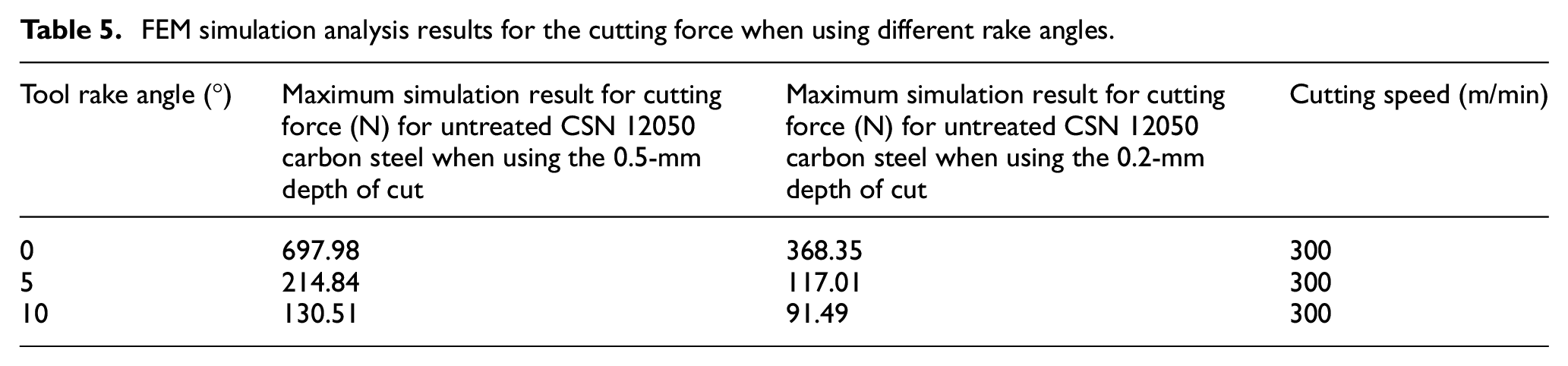
There is also strong evidence that the tool rake angle affects the basic chip morphology process. As such, the cutting force required to produce the chip morphology in the shear zone and at the tool–chip interface should be different when cutting with different tool rake angles. Therefore, the increase in the overall cutting force is considered to be the result of the increased rubbing or ploughing force acting on the cutting tool edge and the rake angle. The rubbing force obtained from the FEA simulations was investigated thoroughly and it was found that this force increases with decreasing rake angle. The plausibility and the generality of the predictive FEA simulation results have been demonstrated sufficiently. Quantitative comparisons between the predicted optimal tool rake angle and the cutting force along with the predicted optimal cutting speed for the tool (α = 0° and 5°) have been performed to examine the adequacy of the obtained FEA simulation results. This comparison is based on the percentage deviations of the predicted FEA simulation values for the tool (α = 0° and 5°) with respect to the corresponding optimal rake angle (α = 10°) and depth of cut (0.2 mm) that were predicted based on the cutting force data using the following equation:

The deviations in the value of the cutting force between the optimal tool rake angle (α = 10°) and the other cases (α = 0° and 5°) show how much the force varies at the optimal 10° tool rake angle when compared with the 0° and 5° rake angles. The quantitative average percentage deviations of the cutting force at the tool rake angles α of 0° and 5° increased by amounts of 75.16% and 21.81%, respectively, when compared with the optimal tool rake angle (α = 10°). Therefore, the simulation result can predict the cutting forces involved in orthogonal cutting adequately through evaluation of the tool rake angle to achieve the ultimate goal of product sustainability.
Comparison of untreated, annealed and recrystallized CSN 12050 carbon steel materials using optimum tool rake/flank (10°/6°) angles to predict the cutting force
The FEM-based chip morphology simulation analysis results confirmed the significant effect of the tool rake angle on the cutting force when using untreated CSN 12050 carbon steel material, as shown in Table 5. Based on these results, a comparison between the FEM simulation analysis results for the untreated, annealed and recrystallized CSN 12050 carbon steel materials was performed to evaluate the optimum conditions when using the optimum tool rake/flank (10°/6°) angles and the optimum depth of cut of 0.2 mm constantly. The chip morphologies obtained when using untreated, annealed and recrystallized CSN 12050 carbon steel performed in the same manner.
A comparison between simulation analysis results for the untreated, annealed, and recrystallized CSN 12050 carbon steels showed that maximum cutting forces of 91.49 N, 63.46 N and 39.36 N were obtained for the untreated, annealed and recrystallized CSN 12050 carbon steels, respectively, as shown in Fig. 8. The results attained from the FEA clearly showed that the recrystallized CSN 12050 carbon steel could be turned with reduced cutting force when compared with the annealed and untreated steels. From these FEA results, it is possible to confirm that the resistance to plastic deformation processes like the turning process was determined by the properties of the materials. Comparison of the untreated, annealed and recrystallized CSN carbon steel materials indicated that the experimental results for both tensile strength and hardness showed good agreement with the FEA simulation results. Therefore, both the hardness and the tensile strength results from the experiments serve as indicators of the CSN 12050 carbon steel’s resistance to plastic deformation (i.e., the turning process).

Cutting force FEA simulation results for untreated, annealed and recrystallized CSN 12050 carbon steel materials using the optimum 10° rake and 6°flank angles for the tool along with the 0.2-mm depth of cut.
Comparison of untreated, annealed and recrystallized CSN 12050 carbon steel materials using optimum tool rake/flank (10°/6°) angles and depth of cut to evaluate the von Mises stress fields
The FEM simulation analysis results for the von Mises stress components were predicted for untreated CSN 12050 carbon steel using different rake/flank angles and depths of cut. To predict the optimum FEM simulation analysis results, comparisons were performed between the untreated, annealed and recrystallized CSN 12050 carbon steel materials when using the optimum tool rake/flank (10°/6°) angles and the optimum depth of cut of 0.2 mm. Figure 9 shows that the result obtained for the von Mises stresses was concentrated in the vicinity of the selected S: Mises at part instance part 1-1 element 1229 integration point. The maximum von Mises stress value was achieved in the FEA simulation results for recrystallized CSN 12050 carbon steel rather than in the FEA simulation results for the material in the annealed and untreated conditions. From Fig. 9, maximum values of 710.17 MJ for recrystallized CSN 12050 carbon steel at a simulation time of 0.25 s, 568.89 MJ for annealed carbon steel at a simulation time of 0.20 s and 468.95 MJ for untreated carbon steel at a simulation time of 0.20 s were determined.

FEA simulation results for von Mises stresses (MPa) of untreated, recrystallized and annealed CSN 12050 carbon steel using tool 10°/6°rake/flank angles, respectively, and the 0.2-mm depth of cut.
Comparison of untreated, annealed and recrystallized CSN 12050 carbon steel materials using optimum tool rake/flank (10°/6°) angles and depth of cut to evaluate the maximum values of ETOTAL vs. time
The maximum values of ETOTAL vs. time for the 10° rake and 6° flank angles for untreated, annealed and recrystallized CSN 12050 carbon steel materials were computed through FEA simulation using a tool with 10° rake and 6°flank angles and the 0.2-mm depth of cut. The results of the simulation showed a maximum value of 76.66 J for the untreated material and reduced values for the annealed and recrystallized CSN 12050 carbon steel materials.
Conclusions
In this study, a finite element model based on the explicit dynamic Lagrangian method in ABAQUS software has been used to study chip morphology in CSN 12050 carbon steel materials. The optimal results that were obtained using FEM modelling and simulation were of a continuous chip morphology produced using a tool with 10° rake and 6° flank angles. The maximum total energy (ETOTAL) and cutting force were obtained when using tools with α = 0° and 5° for the CSN 12050 carbon steel materials for both depths of cut (0.5 mm/0.2 mm). Increased values of von Mises stress and reduced cutting forces were obtained from the FEA simulation results when using a cutting tool with the 10° rake and 6° flank angles. As a result, based on evaluation of the chip morphology simulation work’s output results for the total energy, the von Mises stresses, and the cutting forces, it can be concluded that α = 10° is the optimum cutting rake angle. Furthermore, the results of experiments to measure the mechanical properties of untreated, annealed and recrystallized CSN 12050 carbon steel materials and their chip morphologies showed the good agreement between the predicted chip morphologies and the experimental results.
Footnotes
Handling Editor: Chenhui Liang
Declaration of conflicting interests
The author(s) declared no potential conflicts of interest with respect to the research, authorship, and/or publication of this article.
Funding
The author(s) received no financial support for the research, authorship, and/or publication of this article.