
Abstract
As the centrifugal pump is running, the fluid usually flows into the impeller along pump shaft, and the fluid flows out radially by the force of the impeller. The force is mutual, so the impeller is also subjected to the reaction force of the fluid, but the distribution of this force on the blades is uneven. In addition, the front and rear shrouds of the impeller are asymmetric, which are the main causes of axial force. This paper adopts numerical calculation method studying the mechanism of axial force of impeller at all stages of multistage pump at various working conditions, and exploring the formation mechanism of shroud pressure differential force and blade twisting axial force and its variation laws of similarities and differences, analyzing the steady state and transient characteristics between axial force and hydraulic property of double-casing multistage pump. The results show that the rotational angular velocity of the fluid in the front and rear pump chamber at each stage impeller is distributed along the axial direction in three regions, the regions are pump body boundary layer, core region, and impeller boundary layer. The working surface and back surface of the blade twist have the high and low axial force area, and its distribution is staggered, at the same number of stages, the greater the flow rate, the smaller the blade twisting axial force. The shroud pressure differential force with the increase of impeller stages presents a linear increasing trend, conforms to the principle of linear superposition of cover pressure differential force. The total axial force pulsation of multi-stage pump is related to the number of secondary impeller blades, its primary frequency coincides with the secondary impeller blade frequency, increasing the flow rate can reduce the multi-stage pump axial force pulsation amplitude. The pulsation period of single-stage impeller head and efficiency are related to the number of impeller blades, the smaller the number of impeller stages, the stronger the pressure dynamic, and static interference effect of the impeller inlet and outlet. Rotation of the secondary impeller causes dynamic and static interference, which is the main reason for the pulsation of the axial force coefficient in double-casing multistage pumps, the pulsation intensity is related to the periodic generation and shedding of the blade vortex. The results of the study can be used as a reference for optimizing the axial force of double-casing multistage pumps.
Keywords
Introduction
It is inevitable to produce axial force when multistage centrifugal pump is running, and its size sometimes reaches hundreds of tons1–3 under high pressure. The main reasons are the impeller is subjected to the reaction force of the fluid, the shroud force caused by the uneven pressure distribution of the front and rear pump chamber of the impeller, and the sealing leakage of the multistage pump. 4 The axial force causing the dynamic and static components wear and collide with each other, resulting in the pump cannot run smoothly for a long time, which seriously reduce its service life and overall property. Therefore, balancing axial force is the key to improve pump property. At present, domestic and foreign scholars have made many contributions to the study of axial force in multistage centrifugal pumps. Chuan et al. 5 used numerical calculations to explore the variation law of axial force in a multistage pump. The result shows that regarding the rotational angular velocity of the fluid in the pump chamber as half of the rotational angular velocity of the impeller is the cause of errors in the theoretical calculation, and the primary impeller had a greater axial force than the secondary impeller due to the influence of the leakage flow from the impeller port ring. Zhou et al.6,7 investigated the effect of the front and rear shroud outer diameter of multistage pump impellers on the property and axial force by experimental and numerical calculation methods. The result shows that increasing the front shroud outer diameter could increase the pump head, and a suitable rear shroud diameter could reduce the axial force. Lino et al. 8 received the effect of impeller cover axial distance, flow rate and seal ring clearance on the axial force of multistage pumps, and investigated a calculation procedure for the axial force of multistage pumps, the calculation results are in good agreement with the test results. Gantar et al. 2 used a Laser Doppler Anemometer (LDA) to determine the rotational velocity of the fluid in the impeller side chamber of multistage pump, and analyzed the effect of the rotational properties of the fluid in the side chamber on the axial force of the pump. Bruurs et al. 9 integrated the analytical and CFD methods to calculate the axial force of a multistage pump, but the pressure distribution in the front and rear pump chamber of impeller is different, leading to an error in the axial force value between the integrate method and CFD. Guelichet al. 10 discussed two methods of predicting axial force, the study using a multistage boiler feedwater pump as the object. Baun and Flack 11 carried out a flow visualization study and directly measured the axial force of the fluid in a plexiglass pump, and analyzed the effect of volute shape and number of impeller blades on axial force and hydraulic property. Zou et al. 12 obtained the pressure distribution in the cavity of a chemical centrifugal pump through theoretical calculations. Adding back vanes to the back shroud of the impeller, so that increasing the rotational angular velocity of the fluid in the cavity, and increasing the radial flow, leading to a decrease in the fluid pressure at the shaft seal of the cavity, and increasing the balance force. Lu et al. 13 according to the assumption that the liquid circumferential angular velocity around the impeller is different, deriving the axial force calculation formula after reducing the diameter of the rear shroud of the impeller, and the formula accuracy is verified through tests. Zhang et al. 14 used a modified Eulerian two-fluid model to simulate a two-stage multiphase rotary power pump, the result shows that the combination ratio of air and water in the pump has a more significant effect on the degree of disorder of lift and additional mass forces. He et al. 15 taking the single-stage model of desalination multi-stage pump as the object conducting axial force test, the result presents that the axial force value calculated with the traditional theoretical formula has a certain difference with the test value, but the trend of axial force variation between them is basically consistent. The above study shows that the main factors affecting the axial force of multistage pumps are the circumferential velocity of the fluid in the impeller pump chamber, the axial size of the impeller shroud and the form of fluid motion in the impeller pump chamber. Due to the large number of stages in multistage pumps and the complex internal flow, there is little literature on the influence of impeller geometry parameters on the axial force of multistage pumps.
Multi-stage pump is composed of multiple single-stage impellers, and the research results on axial forces in single-stage pumps can be used as a reference for multi-stage pumps. Nishi and Fukutomi 16 studied the effect of the change in outlet placement angle of single-vane closed centrifugal pumps on axial forces, and the result shows that at large flow rates, the time average value of the axial forces in the front and rear pump chamber increased with the increase of impeller vane outlet angle. Kazakov and Pelinskii 17 carried out an experimental study on axial force of submersible well pump, it was found that the pump axial force increased with the seal gap increased. Li et al. 18 analyzed the effect of the axial width of the front shroud side chamber of impeller on the external property of the pump and the axial force through numerical calculation. The result shows that the larger the axial width, the lower the head and efficiency of the pump. The static pressure in the impeller, back impeller, and sub-impeller varies very little, and the axial force tends to increase first and then decrease. Wei et al. 19 studied the influence of the diameter change of seal ring behind the impeller and balance hole on the fluid flow property of the balance chamber, and found the variation law of the pressure and axial force in the balance chamber. Kan et al. 20 studied the cavitation phenomenon in reverse-operated pumps due to local low pressure, it was found that the reverse mode is more likely to cavitation, and the cavitation performance can be significantly improved by modifying the geometric design parameters of the reverse-operated pump. In addition, domestic and foreign scholars have carried out many studies on the influence of factors such as the leakage of port ring gap and the leakage flow of the balance hole on the axial force.5,21–25 The results show that the pump chamber leakage flow causing the pressure in the pump chamber to change, and forming induce vortices in the cavity so that generating vortex forces, leading to transient changes in axial forces. Shimura et al. 26 pointed out that the fluid leakage in the pump chamber directly affects the calculation accuracy of the axial force equation.
There have many researches on influence of the fluid flow properties in the side shroud, seal ring, and balance hole of a centrifugal pump on the axial force, but the multi-stage pump with a high number of stages, the pump flow properties and axial force changes are complex, there is little literature to explore the variation law of multi-stage pump axial force with the number of impeller stages change. Therefore, analyzing the flow field properties of each stage impeller of multi-stage pump, revealing the relationship between axial force and multi-stage pump hydraulic property, which laying the foundation for multi-stage pump hydraulic property improvement and axial force decrease.
Models and numerical calculation methods
Multistage pump structural parameters
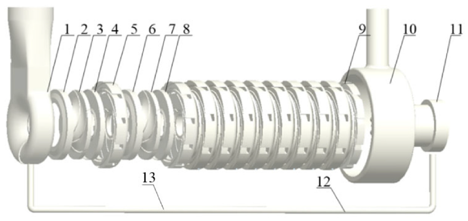
Figure 1 presents the structural diagram of the 11 – stage double-casing multistage pump, and its design parameters are: flow rate Qd = 128 m3/h; number of stages = 11; single stage head Hi = 106 m; rotate speed n = 2986 r/min. There is an orifice plate mounted on the balance pipe. Table 1 presents the main parameters of overcurrent components.

Schematic diagram of double-casing multistage pump.
Main parameters of overcurrent components.

Calculation region and meshing
According to the design parameters of the pump, the model of the pump is drawn by Pro/Engineer software, so as to obtain the calculation region of the fluid. As shown in Figure 2, the calculation region includes: water absorption chamber, primary impeller (stage 1), secondary impeller (stages 2–11), guide blade (stages 1–10), final stage guide blade (stage 11), pressurized water chamber, balance piston, balance pipe, and orifice plate.
Fluid calculation region model.
The hexahedral mesh reduces the solving time, so it is easier to handle the model. Therefore, ICEM is applied to divide the calculation region into hexahedral grids, as shown in Figure 3. Due to the viscosity of the fluid, there are boundary layers when the fluid moves in the near-wall region. In this paper, the near-wall model method is used to deal with the problem of near-wall region, which requires that the wall region be divided into finer grids, the closer to the wall, the finer the grid, so that y+ (dimensionless height from the first layer of the wall) <5. Figure 4 is a grid-independent validation curve based on efficiency and axial force. It can be seen from the figure that the change trend of efficiency and axial force is gradually stable when the number of grids is between 48.62 and 65 million. Therefore, 48.62 million grids can be used for numerical calculation.
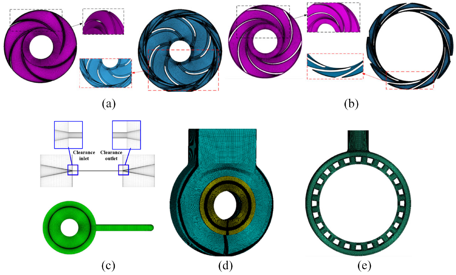
Grid diagram of the main overcurrent components: (a) primary impeller and guide blade, (b) secondary impeller and final stage guide blade, (c) balance piston and gap, (d) water absorption chamber and (e) pressurized water chamber.

The curve of grid-independence verification.
Numerical calculation methods
Compared with the standard model, the SST model can gradually transform the standard k–ω mode inside the boundary layer into the k–e model with high Reynolds number outside the boundary layer, so that the k–ω model has a wide range of applications and accuracy in the near-wall free flow. Its advantage is that it can predict the flow near the wall more accurately, and at the same time, it has a good speculation on the beginning and degree of separation in the strong counter-pressure flow,5,25–27 therefore, SST
Experimental verification of numerical methods
Figure 5(a) shows a test bench of multi-stage pump P101B. Figure 5(b) shows the test bench device. When the unit is in operation, the liquid in the feedstock tank is fed to the reactor through test pump, where a redox reaction takes place.

Schematic diagram of the multi-stage pump property test bench: (a) test bench of multi-stage pump and (b) test bench device.
The test pump and pipe system composed by a multi-stage pump, inlet pipeline, outlet pipeline, feedstock tank, reactor, pressure converter, motor, torque meter, data acquisition instrument, various instruments, and valves. The feedstock tank, regulating valve and pressure sensor could change the flow rate of multistage pump by adjusting the opening of the inlet valve, they are installed in the inlet pipeline and could meet the experimental requirements under different working conditions. An AMD400L2RBABM motor (ABB, Switzerland) is used in multistage pump, which is designed to operate at a pump speed of 2986 r/min. The reactor is installed in the pump outlet pipeline, and the raw material is transported into the reactor for redox reaction through the multi-stage pump. The different flow rate conditions are regulated by the inlet control valve when testing the multi-stage pump hydraulic performance. The error of 7MF403 pressure sensor of Siemens Corporation of Germany is ±0.075%, and the pressure sensor was applied to test the pump inlet and outlet pressure. The error of AE215 electromagnetic flow meter of Ganges Corporation of China is ±0.5%, and the flow meter was used to measure the pump outlet flow rate. The three Current-voltage transformers composed by CTK-38 type open current transformer of Lraq company and DTS634 type three voltage transformers of Zheng Tai Corporation, it was used to measure the power. The MH6150 orifice flowmeter (0.5 stage) was used measuring the flow rate of the balance pipe, the YB-150 standard pressure gauge (0.4 stage) was used measuring the position pressure of the balance pipe, they were mounted of balance pipe axially 153 and 239 mm from the pump inlet.
Figure 6 presents the experimental and simulated values comparison curves of the multistage pump hydraulic properties and balance pipe flow rate and pressure. From Figure 6(a) we can see that the head and efficiency numerical simulation curves are in general agreement with the variation of the test curves, and the numerical and experimental curves are in good tally at the design flow rate, while the error between the two is larger under the small and large flow rate working condition. Besides, the energy loss is generated due to the device sealing and bearing wear, and it not considered by numerical simulation, so the experimental values are always lower than the simulated values, and the errors in head and efficiency are 2.42% and 3.11% respectively under design conditions. For high pressure double-casing multi-stage pumps, verifying the reliability of the calculation method by directly measuring the pump chamber pressure and the balance piston clearance leakage is more difficult, so measuring the pressure and flow rate of balance pipe and comparing to simulation values was used in this paper. From Figure 6(b) we can see that the calculated values and experimental values are basically the same trend, it means that the calculate results could descript the fluid flow properties in the balance pipe better, but the experimental values are always smaller than the simulated values. The numerical calculation curve of the pressure in the balance pipe is in good tally with the experimental curve, the maximum deviation is 2.5%, and the maximum deviation in balancing pipe flow rate at the design operating point is 4.49%, the experimental deviation did not exceed the permissible limits, so the calculation method chosen in this study is dependable.

Numerical simulation and test comparison curves: (a) performance of head and efficiency curve and (b) balance pipe flow and pressure curve.
Analysis of results
Distribution of blade twisting axial force
Double-casing multistage pump belongs to the medium to high ratio centrifugal pumps, in order to improve its operating efficiency, the blade twist degree often increased in designing the blade, resulting in uneven pressure distribution along the axial projection of the blade, and producing the blade twisting axial force. The theoretical formulas in the calculation of the impeller dynamic reaction force only consider the force on the outer surface of the impeller, the inner surface of the axial force is regarded as internal force and is not considered. Therefore, in order to clarify the mechanism of the axial force, it is necessary to study the twisted axial force of blade. In this paper, the first stage, the middle stage (six-stage) and the last stage of the impeller blades are taken as the object of study, the twisted axial force distribution cloud is shown in Figure 7.

Distribution cloud diagram of blade twisting axial forces: (a) 0.8 Qd, (b) 1.0 Qd, and (c) 1.2 Qd.
As can be seen from Figure 7 that with the increase of impeller stages, the blade axial force gradually increases. Under the same number of stages, the higher the flow rate, the smaller the axial force. The axial force distribution of the first stage impeller and the six-stage and last-stage impeller has some variability, and the high and low axial force areas on the working surface and back of the blades of the three impellers are staggered. For the first stage impeller, the axial force at the blade inlet is low, for the six-stage and the last stage impeller, the axial force at the blade inlet is high, this is because the flow speed of primary impeller inlet is influenced by flow rate of water absorption chamber inlet, its flow is uniform, resulting in the blade inlet axial force is small. The six-stage and the last stage impeller inlet are connected to the back guide blade outlet, fluid is diverted through the guide blade, the flow speed increases, so that the axial force of blade inlet appears local high value area.
In order to further analyze the distribution of the mean value of the circumferential twisting axial force along the radial direction of each stage impeller blades, Figure 8 gives the distribution curve of the twisted axial force of the blade under different working conditions, where

Distribution curve of the blade twisting force along the radial direction: (a) 0.8 Qd, (b) 1.0 Qd, and (c) 1.2 Qd.
Figure 9 shows the variation of impeller blade twisting axial force with the number of stages. From the figure it can be seen that at the same working conditions, the blade twisting axial force presents approximately a liner increase trend with the increase of stage number, indicating that the axial force of the blade is gradually increased due to the impeller rotating pressurization. In addition, at the same number of stages, the greater the flow rate, the smaller the blade axial force, this is because the pressure difference of impeller inlet and outlet reduced with the flow rate increased, the pressure difference acts on the blade also reduced.

Variation curve of blade axial force with number of impeller stages.
In order to analyze the root cause of the axial force generated by the twisted blade, the streamline distribution in the guide blades of the first stage, intermediate stage (stage 6), and final stage impellers is selected for analyzing, as shown in Figure 10. It can be seen from the figure that under the same working conditions, with the increase in the number of impeller stages, the streamline of fluid in the impeller flow channel gradually becomes smooth, and the vortex at the impeller inlet is obviously reduced. Under the same number of stages, the number of the vortex at the impeller inlet is gradually reduced with the increase in flow rate. At the impeller outlet, a non-uniformly distributed high-speed zone is visible along the circumferential direction, the number of this zone is the same as the number of guide blade flow channel, it is shown that the dynamic and static interference between the impeller and the guide blade is strong, resulting in a high value area of the flow velocity at the impeller outlet. Under the design conditions, the number of the vortex in the guide blade at different stages is small, and the number of the vortex in the guide blade at low and high flow rate is large. It can be seen from the flow characteristics of the fluid in the dynamic and static blade lattice that the main reason for the twisted axial force of blade is the increase of the vortex band in the impeller flow channel, impeller outlet and blade and other local areas.

Streamline diagram of different impellers and guide blades: (a) 0.8 Qd (b) 1.0 Qd (c) 1.2 Qd.
Differential pressure force distribution between front and rear shroud
Differential pressure force in front and rear shroud of pump chamber is the main factor affecting the axial force of multistage pumps,5,26–29 in addition, the liquid rotational angular velocity in pump chamber on the shroud differential pressure force has a great impact, 30 its rotational angular velocity distribution is also more complex, so studying the rotational angular velocity in front and rear pump chamber of double-casing multistage pumps can provide theoretical support for accurately calculating the shroud differential pressure force.
Figure 11 shows the radial distribution curve of the circumferential mean value of the rotational angular velocity of the fluid in front and rear pump chamber of each stage impeller, where

The radial distribution law of rotating angular velocity in front and rear cavities of each stage impeller: (a) front chamber and (b) rear chamber.
On the basis of analyzing the generation mechanism of the differential pressure force between the front and rear shroud of the double-casing multistage pump, the distribution law of the differential pressure force of the shroud at each stage impeller is further studied. Figure 12 shows the variation curve of the shroud force in front and rear pump chamber with impeller stages under different working conditions. As can be seen from the figure that the higher the flow rate, the lower the head, the smaller the difference pressure between the impeller inlet and outlet, resulting in a lower pressure of the pump chamber liquid and a reduced differential pressure force on the shroud. The pressure differential force of impeller shroud increases linearly, and in line with the linear superposition principle. The linear runaway rate of the last stage impeller is 8.2%, 4.5%, and 9.3% under the three working conditions of 0.8 Qd, 1.0 Qd, and 1.2 Qd respectively.

Distribution law of differential pressure forces in front and rear pump chamber of impeller shroud with the number of stages.
Correlation analysis between axial force characteristics and hydraulic property of double-casing multistage pumps
Figure 13 shows the variation of the axial force of each stage impeller with the number of stages and flow rate. It can be seen from the figure that the larger the stage, the greater the axial force. Compared with the first stage impeller, the axial force of the last stage impeller increases by 81.3 times, 51.2 times, and 36.7 times under three operating conditions of 0.8 Qd, 1.0 Qd, and 1.2 Qd respectively, indicating that the smaller the flow rate, the more obvious the increase in the axial force of the first and last stage impellers. The difference in axial force gradually increase with the increase of flow rate, for the first stage impeller, the difference in axial force (relative difference percentage between 1.2 Qd and 0.8 Qd) caused by the increase in flow rate is only 1.05%, while for the last stage impeller, the difference caused by the increase in flow rate increases to 11.03%, indicating that for the double casing multistage pumps, the larger the number of impeller stages, the more obvious the increase in axial force caused by flow rate increases. The above analysis shows that the axial force of the double-casing multistage pump is influenced by the number of impeller stages and the flow rate, and the axial force gradually increases with the increase of stages and decreases with the increase of flow rate.

Variation of total axial force of each stage impeller with the number of stages.
As the axial force of the double-casing multistage pump is hundreds or even thousands of times that of the single-stage pump, 8 the axial force pulsation will lead to bearing and shell vibration, but there is relatively little research on the axial force pulsation of the double-casing multistage pump. In order to clarify the effect of impeller rotation on the characteristics of axial force pulsation, it is necessary to analyze the time domain and frequency domain characteristics of axial force pulsation. Figure 14 gives the time domain and frequency domain diagrams of the axial force of a double-casing multistage pump. As can be seen from Figure 14(a) that the impeller axial force has six similar waveforms in a rotational period at different flow rates, and the same as the number of secondary impeller blades, this is because the rotational effect of the secondary impeller blades has a great impact on the pump pressure, resulting in a period of axial force pulsation related to the number of secondary impeller blades. The maximum fluctuation amplitude in axial force is 29.85, 25.71, and 20.88 kN for the three operating conditions of 0.8 Qd, 1.0 Qd, and 1.2 Qd respectively, it indicates that with the increase of flow rate, the head decreases, the impeller fluid pressure pulsation decreases, and the axial force amplitude decreases. Fourier transform of the axial force time domain diagram could obtain the frequency domain diagram of the impeller axial force, as shown in Figure 14(b). As can be seen from the figure that the primary frequency amplitude of the impeller axial force is the same as the secondary impeller blade frequency, they are both 298 Hz, indicating that the axial force interference frequency is mainly determined by the secondary blade passing frequency. With the increase of the flow rate, the main frequency amplitude decreases, and compared with the 0.8 Qd flow rate, the primary frequency amplitude at 1.0 Qd and 1.2 Qd flow rates decrease by 13.9% and 19.4% respectively, indicating that the increase of the flow rate can reduce the axial force pulsation amplitude.

Time and frequency domain diagrams of axial force pulsations in double-casing multistage pump: (a) time domain diagram of axial force pulsation and (b) frequency domain diagram of axial force pulsation.
The flow between the impeller and the guide blade of the double-casing multistage pump is complex, and the hydraulic property of each stage impeller has some variability. Therefore, investigating the relationship between impeller hydraulic performance and flow rate and number of stages, which can provide a theoretical basis for the analysis of axial force mechanism. Figure 15 shows the variation curve of impeller hydraulic property of the double-casing multistage pump with the number of stages. From the Figure 15(a) can be seen that the impeller inlet and outlet pressure difference show an irregular change with the increase in the number of stages, the first stage impeller head is generally higher, and the last stage impeller head is generally lower, this mainly because there is a cavitation at first stage impeller inlet, so that the impeller inlet negative pressure increases, the head increases. The last stage impeller influenced by the outflow of pressurized water chamber, the impeller outlet pressure decreases, the head decreases. With the flow rate increases, the head of each stage impeller decreases. As can be seen from Figure 15(b) that the impeller efficiency is larger at the design working condition point and smaller at the small flow rate working condition. Under the same working condition, the efficiency of the first stage impeller decreases significantly compared with other stages, and the efficiency of the last stage impeller increases slightly.

Variation curve of the hydraulic property of each stage impeller of double-casing multistage pump: (a) head and (b) efficiency.
In order to further clarify the variation law of hydraulic property of each stage impeller with time, considering the large number of stages of the double-casing multistage pump, and in view of the limitation of extent, this paper only analyses the pulsation characteristics of the head and efficiency of the first stage, middle stage (six-stage), and final stage impellers with time under the design conditions, and the time and frequency domain diagrams are shown in Figures 16 and 17 respectively. It can be seen from Figure 16(a) that the head is pulsating periodically within one period of impeller rotation, and the number of pulsating waves is the same as the number of impeller blades at each stage, the first stage impeller has five fluctuation periods (its blades number is 5), the sixth stage impeller and the last stage impeller have both six fluctuation periods (its blades number is 6). The average values of head pulsation within one period for first-stage, sixth-stage, and last-stage impeller are 122.5, 110.7, and 107.0 m respectively. Figure 16(b) shows the frequency domain diagram of the head pulsation of impeller at each stage. As can be seen from the figure that within one period of impeller rotation, the primary frequency of head pulsation of the first stage impeller is the first impeller blade frequency (248.85 Hz), and the primary frequency of the secondary impeller is the secondary impeller blade frequency (298.6 Hz), and with the increase of the number of stages, the amplitude of the primary frequency is gradually decreasing, indicating that the dynamic and static interference effect of impeller inlet and outlet pressure is strong under the small number of stages.

Time and frequency domain diagrams of head pulsation of the first, sixth, and last stage impeller: (a) time domain diagram of head pulsation and (b) frequency domain diagram of head pulsation.

Time and frequency domain diagrams of efficiency pulsation of the first, sixth, and last stage impeller: (a) time domain diagram of efficiency pulsations and (b) frequency domain diagram of frequency pulsations.
Figure 17(a) shows the time domain diagram of the efficiency pulsation of each stage impeller. From the figure it can be seen that the peak values of the efficiency pulsation are the last stage impeller > sixth-stage impeller > primary impeller, indicating that the amplitude of the efficiency pulsation gradually increases with the increase of the number of stages. Within one rotation period of the impeller, the efficiency pulsation of the first stage impeller shows five similar waveforms, which is the same as the number of blades of the first stage impeller, while the efficiency pulsation of the sixth-stage and last-stage impellers show six similar waveforms, which is the same as the number of blades of the secondly stage impeller, indicating that the number of blades is the main reason for the fluctuation of the impeller efficiency. In addition, the average efficiency values of the first-stage, sixth-stage, and last-stage impellers in one period are 45.98%, 71.32%, and 75.9% respectively, showing a gradual increase trend. Figure 17(b) shows the frequency domain diagram of impeller efficiency pulsation. It can be seen from the figure that the primary frequency of the efficiency pulsation of the first stage impeller is the first stage impeller blade frequency, and the primary frequency of the efficiency pulsation of the sixth and last stage impellers is the secondary impeller blade frequency, and the amplitude of the primary frequency of the efficiency gradually increases with the increase of the number of stages.
Through the above analysis, it can be seen that the internal flow mechanism of double case multistage pump is complex, and the distribution of axial force and head at each stage of the impeller is not consistent, therefore, in order to further clarify the relationship between axial force and hydraulic property, in this section, the head is taken as a reference variable for it is the main performance parameters that affects the axial force, establishing the relative coefficient between head and axial force of double-casing multistage pump, which is defined as the axial force coefficient.

In the formula, Fi is the total axial force of the single-stage impeller, N. Hi is the single-stage impeller head, m.

Variation curve of axial force coefficients with number of stages.
In order to analyze the pulsation characteristics of the axial force coefficient of the multistage pump with time in detail, Figure 19 shows the time domain and frequency domain diagrams of the pulsation of the axial force coefficient of the multistage pump under different operating conditions. As can be seen from Figure 19(a) that the axial force coefficient has six similar waveforms in one rotation period, which is the same as the number of secondary impeller blades. The peak value of the axial force coefficient is the largest in the small flow rate condition, followed by the large flow rate condition and the smallest in the design condition, indicating that impeller parameters match well under design flow rate, which weakens the fluctuation of the axial force coefficient. Compared with 0.8 Qd, the axial force coefficients of 1.0 Qd and 1.2 Qd are reduced by 6.49% and 5.22% respectively in one period of the internal average value. Figure 19(b) shows that the primary frequency of axial force coefficient coincides with the blade frequency of secondary impeller under different working conditions, this indicates that the dynamic and static interference of the secondary impeller is the main reason for the fluctuation of the primary frequency of the axial force coefficient. The amplitude of the primary frequency of the axial force coefficient is the largest in the low flow rate condition and the smallest in the design condition, this is because the impeller blades at small flow rate conditions are prone to flow instability such as off-flow and stall, while the flow in the design condition is smoother and the streamline is smoother, which weakens the pulsation amplitude of axial force coefficient. In addition, there is an obvious excitation frequency in the low frequency band, which is caused by the periodic generation and shedding of the high strength vortex structure at the impeller outlet.

Time and frequency domain diagrams of axial force coefficient pulsations: (a) time domain diagram and (b) frequency domain diagram.
Based on the above analysis, it can be seen that the rotation of secondary impeller leads to the enhancement of dynamic and static interference, which is the main reason for the fluctuation of axial force coefficient of double-casing multistage pump, its strength is associated with the periodic generation and shedding of vortices in the impeller.
Conclusion
The rotational angular velocity of the fluid in the front and rear pump chamber of each stage impeller is distributed along the axial direction in the three regions of the pump body boundary layer, core area, and impeller boundary layer, and the rotational angular velocity of the fluid in the cavity is half the rotational angular velocity of the impeller for the approximate rigid body motion.
The high and low axial force area in working and back surface of the blade twisting axial force is staggered distribution, at the same number of stages, the larger the flow rate, the smaller the blade twisting axial force. The shroud pressure differential force with the increase in the number of stages is a linear increasing trend, and in line with the linear superposition principle of the shroud pressure differential force.
The correlation analysis of axial force characteristics and hydraulic properties shows that: (a) The axial force of multi-stage pumps under different working conditions all reach more than 10 tons, indicating that the balance of axial force of double-casing multistage pumps is an important factor affecting their safe and stable operation. (b) The total axial force pulsation pattern of the pump is related to the number of secondary impeller blades, and its primary frequency coincides with the secondary impeller blade frequency, increasing flow rate can reduce the amplitude of axial force pulsation in multistage pump. (c) The pulsation period of single-stage impeller head and efficiency are related to the number of impeller blades, the smaller the number of impeller stages, the stronger the dynamic and static interference effect of the impeller inlet and outlet pressure. (d) The main reason for the pulsation of the axial force coefficient of the double-casing multistage pump is the dynamic and static interference caused by the rotation of the secondary impeller, its strength is related to the periodic generation and shedding of the impeller vortex.
Footnotes
Handling Editor: Chenhui Liang
Author contributions
The first author is Qian Chen who did the paper writing and data calculation. The second author is Yang Li Huan who did the data calculation and experimental debugging. The third author is Qi Zhi Peng who made a summary of paper ideas. The fourth author is Yang Cong Xin who made the experimental measurement.
Declaration of conflicting interests
The author(s) declared no potential conflicts of interest with respect to the research, authorship, and/or publication of this article.
Funding
The author(s) disclosed receipt of the following financial support for the research, authorship, and/or publication of this article: The study is supported by Lanzhou University of Technology Hongliu Outstanding Youth and Open Research Subject of Key Laboratory of Fluid Machinery and Power Machinery (Xihua University), Ministry of Education (Number: LTDL 2021-010).