
Abstract
There is inevitably an angular offset during contact of mechanical structures such as roller bearings or gears. Most of the previous contact models involve the contact between two parallel cylinders. This paper introduces the angle parameter into the model constitutive relation for the first time. A new cylindrical contact model is proposed to simulate the contact at different angles. In this paper, a cylinder contact model with different axis crossing angles is proposed. The load-displacement curves of the contact model during loading and unloading are provided via theoretical derivation of the normal and tangential contact processes of the contact model. On this basis, the hysteresis curve model of the contact model is established. Through finite element modeling and finite element analysis, the cylinder hysteresis curve models under different axis crossing angles are verified. Compared to other common models, the energy dissipation of the cylindrical model is higher. By introducing the angle parameters into the model constitutive, it provides ideas for solving the macro contact problems such as cylindrical gear contact and rolling bearing. At the same time, on the micro-contact problem, it provides a theoretical basis for the tangential contact process of the regular joint surface.
Keywords
Introduction
When two contact models in contact with each other slide against each other, elastic and plastic deformation may occur before macroscopic slip occurs. This elastic and plastic deformation is called micro-displacement or micro-slip. The frictional load-displacement relationship obtained during micro-slip is similar in shape to the stress-strain relationship for brittle materials. Fretting wear and fretting fatigue are the two main causes of tribological failure. Local slip conditions mainly lead to mechanical failure of surface crack initiation and propagation, while macroscopic slip conditions lead to wear. 1 The purpose of this paper is to propose a new cylindrical contact model and gain insight into the mechanism of fretting wear.
Johnson 2 conducted a theoretical analysis of fretting wear. He provides elastic solutions for contact pressure, tangential force, and contact surface deformation. Fixed cylindrical and spherical contact issues in partial and total slip situations. Fretting occurs when a preloaded contact is subjected to a low-amplitude tangential oscillation displacement or force. During the fretting process, the contact may be in a partial slip state (part of the contact area is completely bonded and the remaining contact area slips) or simultaneously in a partial slip and a total slip state. This pre-slip response was first calculated by Cattaneo 3 and Mindlin 4 for pre-loaded spherical contacts. Mindlin et al. 5 proposed the cyclic loading response of elastic contact. Ödfalk and Vingsbo 6 extended the cyclic loading response to elastic-plastic contact. For dynamic tangential loads, the contact interface can store and dissipate energy, thereby resulting in tangential contact stiffness and frictional damping. In addition, tangential stiffness and frictional damping play an important role in the dynamic performance of joints and contact structures. Mindlin and Deresiewicz 7 investigated the tangential contact stiffness and friction hysteresis curve of a half-space sphere. The hysteresis curve is used to predict nonlinear contact stiffness. Goodman and Brown 8 measured the hysteresis curve at the contact point of a sphere swinging between two parallel plates. The value of energy dissipation was consistent with the value found in Mindlin’s work. The relative displacement of tangential motion was higher than half of the critical displacement. Their research provides a good reference for the follow-up research on dynamic contact.
Yang and Green 9 conducted a finite element study of plane-strain cylinders using displacement-controlled fretting. It was found that the edges of the contact area experienced large von Mises stress and significant residual plastic strain, while accumulation may also occur when the friction coefficient is large enough. Meanwhile, Yang and Green 10 in another study on fretting wear of cylinder line contact. An empirical formula was developed for the first time to predict the fretting wear of plane strain line contacts under friction conditions, and this was demonstrated by FEA. Sharma and Jackson 11 proposed an elastic-plastic cylinder contact model, which was studied using a finite element method. The cylinder is considered to be in a state of plane stress. Using symmetry, model the cylinder as a quarter circle. The finite element results for elastic and fully plastic cylindrical contact cases are compared with other existing models such as Hertzian contact and spherical elastoplastic models. The models used in the above studies are all cylinder-plane contact models, and no analysis of the contact model of two cylinders that interfere with each other is carried out, let alone the analysis of the contact angle. Ahmadi et al. 12 developed an in-situ fretting wear measurement technique to study the effect of temperature (750°C) on the friction coefficient and wear rate of Inconel 617 during fretting wear in air and helium environments. It was found that the wear rate exhibited bilinear behavior as fretting wear proceeded at room temperature and in air. Yang and Green 13 used the finite element method to study the two-dimensional plane strain fretting model, and assigned Inconel 617 and Incoloy 800H to the semi-cylinder and the plane block, respectively. It was found that the edge of the contact region experienced large von Mises stress and significant residual plastic strain. And when the coefficient of friction is large enough, accumulation may also occur. However, the research on the loading and unloading process is only the finite element simulation solution, and the analytical solution of the specific loading and unloading between the cylinder and the plane block is not given. In addition to the above-mentioned study between a cylinder and a flat block, Jackson and Green 14 presented a finite element study of elastoplastic hemispherical contact. The results are normalized so that they apply to both macroscopic contacts (such as rolling element bearings) and microscopic contacts (such as roughness contacts), although microscale surface features such as grain boundaries are not considered. Yang and Green 15 also proposed a contact model between an elastic-plastic sphere and a plane, and studied the tangential direction by means of FEA. The displacement is controlled in the tangential direction. The materials of the two contact bodies have the same properties. A normalization scheme is proposed and shown to be effective for the above two materials with distinct material properties. Thereafter, Yang and Green 16 established a comprehensive adhesion model of the deformable hemisphere affected by fretting through finite element. The hemisphere is constrained between two rigid frictionless plates as it is loaded in the normal direction and then undergoes an oscillatory tangential motion. It is also controlled by tangential displacement. The use of linear springs at the contact location to simulate fracture and springback at the interface makes the stick model less structurally stiff. For the analytical solution of the hemispherical elastoplastic model, Boucly et al. 17 proposed a semi-analytical method for 3D elastoplastic contact of hemispherical asperities. The normal and tangential directions can be either displacement-driven or load-driven. And the correctness of the model is verified by finite element method. Much of the previous work on hemispherical contact has been devoted almost entirely to quasi-static normal loads (axisymmetric 2D models). There is some scarce work on tangential loads, and most models focus on contact between spheres and planes. Green 18 studied mutual sliding between two hemispheres with the aim of applying the results to interfering asperities in sliding rough surfaces. A finite element method was used for the study, and empirical formulas for net energy loss, permanent residual deformation (damage) and effective coefficient of friction (frictionless sliding) were given. Compare the results obtained by the semi-analytical method with the finite element results. But these results are limited to the few special cases that the former is able to address. Considering that there is not only spherical contact in the actual mechanical structure, but also cylindrical contact in some structures such as gears or bearings. Guo et al.19–21 proposed an elastic-plastic contact model between two cylinders, a cosine cylinder contact model, and a parabolic cylinder contact model. The model is based on the Hertz theory, and the analytical solutions of the normal contact load and displacement are given, which are verified by FEA. For the first time, the influence of the contact angle on the mechanical properties of the model is considered in the model. Introduce the contact angle into the model constitutive. However, the model does not consider the effect of tangential loads. In the follow-up study, 22 on the basis of normal contact, the influence of tangential load on the parabolic cylinder contact model was considered. The analytical solution between tangential load and tangential displacement is also given. It is compared with the results of FEA. Popov et al. 23 proposed a method that is directly applicable to the viscous contact of any rotating body with a small contact area. Using the generalization of the superimposed normal/tangential adhesive contact dimensionality reduction method, the adhesive strength of the contact between the rotationally symmetric indenter and the elastic half-space is analyzed analytically and numerically. In other fields, Li et al. 24 proposed to study the loading and unloading process of adhesive contacts at the atomic point of view. A molecular dynamics simulation model considering material anisotropy and adhesion is established to study the loading-unloading behavior during nanoindentation in spherical contact. Differences between macroscopic and nanoscale scales were identified by comparison with analytical Hertzian solutions, JKR and DMT models. In terms of experiments, Zhu et al. 25 developed a composite fretting test device for inclined steel balls with different inclination angles. The fretting behavior of the composites was analyzed and compared with conventional fretting. McColl et al. 26 proposed a wear model between a cylinder and a plane. The friction and wear coefficients applicable to the contact structure and load conditions were determined using fretting tests. Wear simulation techniques are incremental in nature, and through mesh and incremental size optimization, total simulation time is minimized. The predicted wear profiles were compared with profilometer measurements of fretting test scars. Kim and Lee 27 proposed a criss-crossed cylinder fretting model in the background of a nuclear-powered steam generator. Fretting wear tests were carried out under different vibration amplitudes and normal loads. Sliding wear and fretting wear test results show that stick-slip wear has a strong influence on fretting wear behavior. However, the model only analyzes the contact model with an axis crossing angle of 90 degrees, and does not introduce the variable angle into the constitutive relationship.
In a recent study, Zhang and Etsion 28 proposed a coupled Euler-Lagrangian model with explicit dynamic analysis and power-law strengthening based on the existing elastic-plastic spherical contact finite element model. Wang et al. 29 proposed a friction model with a contact stiffness criterion and studied the case from a partially slip state to a fully viscous condition. A finite element simulation is performed using the provided model to render the friction diagram. Wang et al. 30 investigated the elastic-plastic contact behavior between a deformable 3D sinusoidal roughness and a rigid plane under combined normal and tangential loads using a finite element method. The resulting junction growth and coefficient of static friction are investigated, providing an empirical expression for the coefficient of static friction. Thereafter, Wang et al. 31 proposed a possible harmonic description of the shape between measurement points. This is achieved by using harmonic interpolation. The effect of resolution on contact characteristics under normal loads and combinations of normal and tangential loads is investigated. This study provides a method for finite element analysis of rough surface contact, potentially bringing simulation results closer to reality. Saha and Jackson 32 analyzed and quantified the behavior of elastic and elastic-perfectly plastic axisymmetric sinusoidal surfaces in contact with a rigid plane. The numerical results agree well with the Hertz model and the Jackson-Green elastic-plastic spherical contact model at low loads. Should be useful in rough surface contact modeling, lubrication analysis, electrical contact modeling, and many other applications. Gao et al. 33 proposed a normal contact stiffness and damping model for two anisotropic rough surfaces, including the effects of shoulder-shoulder contact roughness and adjacent roughness interactions. A series of simulation experiments reveal the influence of contact matching degree and contact anisotropy on normal contact stiffness and contact damping. On the experimental side, Lyashenko and Borysiuk 34 developed laboratory facilities for the study of contact phenomena, which can be used to measure the force between two contact bodies and analyze the evolution of the contact area. The results show that the tangential displacement system exhibits a stationary stick-slip motion pattern with a “sticky spike” at the beginning of the indenter motion. Chen 35 investigated the yield resistance of coated spheres subjected to normal contact loads based on finite element analysis. Medium-hard coatings omitted from previous literature were considered.
The purpose of this paper is to propose a cylinder micro-slip model based on different axis crossing angles. The contact model is subjected to a combination of normal and tangential loads, taking into account the angle of axis intersection between the contact models. The load-displacement curve in the contact process is obtained, and then the hysteresis curve of the contact model in the micro-slip state is deduced. After the whole contact model loading and unloading process is proposed, the hysteresis curve under the micro-slip state is simulated and verified by FEA. The verification results show that the FEA solution and the theoretical solution correspond well. Based on the analytical solution, the effects of different parameters on the shape of the hysteresis curve and energy consumption were explored. The tangential load-displacement relation of the contact model, the hysteresis curve model and the energy dissipation model are presented in Section 3. Verification and analysis based on the finite element model are presented in Section 4. Explore the effects of different parameters on the model in Section 5.
Theoretical background
As shown in Figure 1, the cylinder is subjected to the combined action of the normal load P and the tangential load F, resulting in the corresponding normal displacement

Schematic diagram of the cylinder contact model: (a) under normal and tangential loads and (b) slip direction.
Micro-slip is a small amplitude oscillation that occurs between two contacting objects in various mechanical systems. Although the magnitude of micro-slip is small, micro-slip can cause severe localized damage to materials through wear and fatigue. Micro-displacement usually occurs when the magnitude of the displacement is small and there is no relative slip between the partially contacting contact surfaces. This condition is called localized stick-slip. On the other hand, fretting wear becomes the main cause of fretting damage when the displacement magnitude is large enough that the entire contact area experiences relative sliding. This is called macro-slip. The identification of these different fretting conditions is usually performed by looking at the shape of the hysteresis curve, which is a plot of traction load versus corresponding displacement. Vingsbo and Söderberg 36 first found that in local stick-slip, the shape of the hysteresis curve is elliptical, as shown in Figure 2(a). In macro-slip, the hysteresis curve will expand into a parallelogram shape, as shown in Figure 2(b).

Schematic diagram of the hysteresis curve: (a) ellipse hysteresis curve in local stick-slip zone and (b) parallelogram hysteresis curve of macro-slip zone.
Model
Tangential contact model
The normal load is applied to the contact model. In addition to keep the normal load constant, the tangential load is applied to the contact model. Hence, the contact model produces tangential displacement. The contact state is shown in Figure 3.

Cylindrical contact schematic: (a) load input and displacement output and (b) cylindrical dimension and displacement direction.
Analogous to the normal contact problem and by employing the half-space approximation, tangential displacement of the surfaces of the two contacting objects near the contact surface can be expressed as 2 :
where


The R is the polar radius, the equivalent shear modulus, G, is expressed by:

The equivalent elastic modulus, E, is expressed by:

where E1 and E2 are the elastic moduli of the two cylinders, respectively,
The combined contact problem when the tangential load and the normal load are applied is discussed. For example, it can be imagined that two cylindrical contact models are squeezed together under the action of the normal load P. Then, a load F is applied along the tangential direction. Assuming dry friction exists between two cylindrical contact models, according to the simplest form of Coulomb’s law of friction, the maximum static friction stress

Adhesion occurs under the following condition:

Assuming no sliding is present between two surfaces, equations for the distribution of the normal stress

where
The parameter

The parameter
Based on equation (8), normal stress at the boundary is close to 0 and the tangential stress approaches infinity. Thus, the contact boundary can never satisfy
Tangential stress distribution expressed by equation (9) is proposed under the premise that the contact surface is completely free of sliding. Therefore, it is not applicable when sliding occurs. Hence, it is necessary to seek a new form of tangential stress distribution that accounts for sliding. Then, a combination of known tangential stress distribution equations can be used to construct the correct tangential stress distribution. By superimposing two Hertzian stresses, a new tangential stress distribution that satisfies boundary conditions can be obtained as follows:

Where
During the tangential contact process, identical top and bottom cylinders are used. To produce constant tangential displacement, the tangential load F is applied to one of the cylindrical models. Then, according to the interaction force, the tangential displacement produced by the other cylindrical model is -U. The two cylinders can be kept in balance, with the relative displacement produced between the two cylinders being 2U. Therefore, based on the tangential stress distribution condition equation (12), the analytical expression of the tangential displacement of the cylinder can be expressed as:

Where the integral constant can be expressed by:
By employing different axial crossing angle
Cylindrical tangential contact stiffness is obtained:

Fixed normal load and increasing tangential load
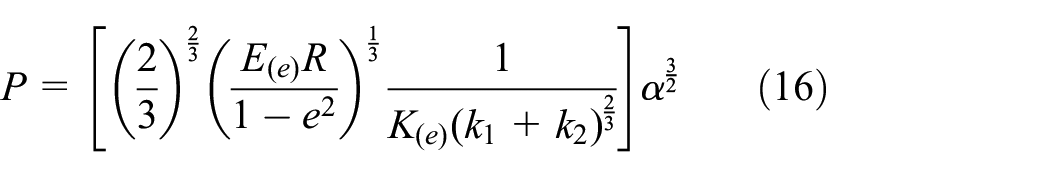
The relationship between normal load and normal displacement can be expressed as 20 :
The cylinder is subjected to a tangential load. The relationship between tangential load and tangential displacement is given in Section 3.1:

When
Fixed normal load and oscillating tangential load
Suppose that the tangential load starts to decrease after reaching the load value

The corresponding ultimate tangential displacement at unloading is twice that at loading:

The loading and unloading process of the cylinder contact model is shown in Figure 4.

Oscillating tangential load.
When the cylinder is unloaded, the slippage must be reversed. However, the absolute value is not changed. Therefore, the sliding part of the cylinder during unloading is twice that of loading. Suppose that the tangential load decreases after reaching the load value

Assume that the tangential load swings between

Frictional energy dissipation
The dynamic contact of two cylinders under normal and tangential loads is a complex non-linear problem of dry friction. A normal load acts on the cylinder to create a positive pressure, and a tangential load acts on the cylinder to cause it to slide. During the contact process, positive pressure is a necessary condition for the generation of Coulomb friction. Therefore, Coulomb friction is used to calculate the frictional energy dissipation during tangential contact.
The cylinder contact model is loaded normally and slides tangentially. Under the action of the dynamic tangential load of the reciprocating tangential motion, the contact surfaces appear to stick and separate. As shown in Figure 5, the energy dissipation can be calculated from the hysteresis curve of tangential friction load versus tangential displacement.

Tangential load and tangential displacement: (a) local stick-slip zone (W1 is the energy dissipation of hysteresis loop 1) and (b) macroscopic slip zone (W2 is the energy dissipation of hysteresis loop 2).
Here, we calculate the frictional energy dissipation from local stick-slip to macro-slip in the contact zone. The area enclosed by the curve
If the tangential load is lower than the maximum friction load, the contact area is in a local stick-slip state. By simultaneously applying equations (24) and (25), frictional energy dissipation of local stick-slip can be written as:

When the tangential load reaches maximum friction load, the cylinder begins to slide along the tangential direction. The displacement along the tangential direction is denoted as

Therefore, the energy dissipation in the reciprocating contact cycle of the contact model is written as:

The cylinder contact model is mainly based on different axis crossing angles, and the angle parameters are introduced into the model constitutive. In contacting mechanical structures such as roller bearings or gears, angular misalignment is inevitable. The modeling ideas with different axis crossing angles provided in this paper can effectively solve such problems. At the same time, the energy dissipation expression of the model in the contact process is given, which can effectively evaluate the energy loss of the model in different contact states.
Finite element model
As shown in Figure 6(a), the micro-movement arrangement in this paper is established for the contact between two cylinders. The coordinate system X-Y-Z is shown in Figure 6(b). The origin of the coordinate system is at the center of the top of the upper cylinder. Two mechanical models relative to the X-Y plane are consistent. The interface between the two cylinders is described by the Coulomb friction with the coefficient of friction 0.2, which corresponds to the value obtained by equation (6). Due to the tangential adhesion effect, tangential traction occurs when the lateral micro-movement occurs.

The established cylinder model: (a) load schematic and (b) coordinate system.
The loading conditions are load-controlled in the Z-direction and displacement-controlled in the X-direction. In order to keep the uniform normal displacement on the upper cylinder constant, a normal load P is applied to the upper surface of the upper cylinder. Under the condition of constant external force, a tangential displacement U is applied to the upper surface of the hemisphere to simulate the fretting motion. It is worth noting that U is not a displacement at the contact interface. Cylinders have stiffness, so there is less displacement at the point of contact. A detailed discussion can be found in Yang and Green. 10
Tangential displacement U is applied through discrete loading steps on the top of the deformable cylinder. The behavior of the tangential displacement is shown in Figure 7. It takes 40 steps to complete a jog cycle. The amplitude of the movement is 0.2 mm. The cylinder starts from the position shown in Figure 6, which corresponds to the designated position “A” denoted in Figure 7. Then, the cylinder moves to the farthest position in the positive direction of the X-axis designated as position “B.” Next, the cylinder returns to its original position, which is recorded as position “C.” As the cylinder moves further backward, it reaches the farthest point of the negative position on the X-axis. This position is recorded as position “D.” Finally, the cylinder returns to its original position, that is, position A.

Loading steps on the top surface of the cylinder used for the micro-motion cycle.
Using Hypermesh to build finite element models with different axis crossing angles, it is shown in Figure 8. Import the established finite element model into the finite element software Abaqus for FEA.

Finite element model: (a) 45°, (b) 60°, and (c) 90°.
Simulation convergence is mainly affected by the number of interface contact elements between the two cylinders. The mesh on the interface is increased until the difference in the contact area between two mesh refinements is lower than 3%, due to external force, the contact area increases with the number of contact elements and due to the size of the tangential load (Figure 9). With more than 300 contact units, the change in the contact area is relatively small. Therefore, it is concluded that 500 contact elements are sufficient.

Variation law of the contact area with respect to the number of cells.
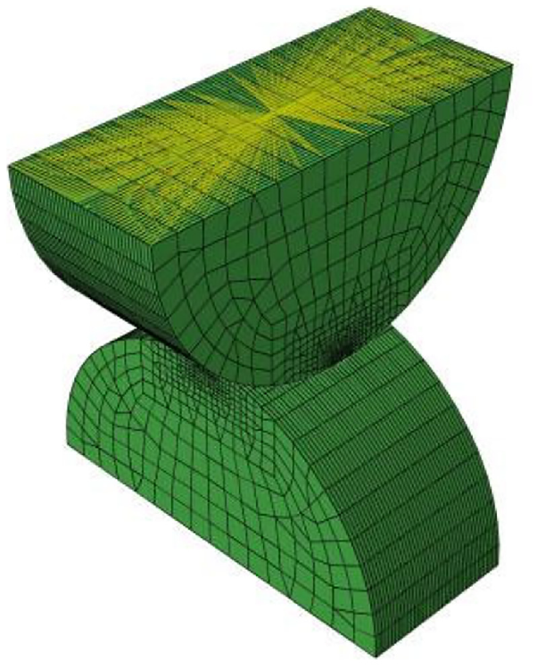
The element type used is designated in ABAQUS as C3D8R, the number of elements is 250,000 with the corresponding number of nodes being 2,659,682. Elements in the contact region are refined according to Figure 10.

Schematic diagram of the grid of contact parts: (a) overall mesh, (b) contact site mesh and (c) contact site mesh enlargement.
Import the finite element model established in Hypermesh into Abaqus for FEA. First define the material properties, which are shown in Table 1. The model used in the analysis in this paper is the elastic-plastic material model. Assign the defined material properties to the two cylinders models.
Material properties of the model.

Plasticity is a material property that produces permanent material deformation under a given load. For most engineering materials, when the stress is lower than the proportional limit, the stress-strain relationship is linear. Most materials exhibit elastic behavior when the stress is lower than the yield point.
Metal engineering stress is called the nominal stress, and its corresponding strain is called the nominal strain. The data obtained in uniaxial tension and compression experiments are usually given in terms of nominal stress and nominal strain. In ABAQUS, true stress and strain values can be used to define plasticity. However, most test data are often provided as nominal stress and strains. Hence, the nominal stresses and strains must be converted to true values according to certain equations.
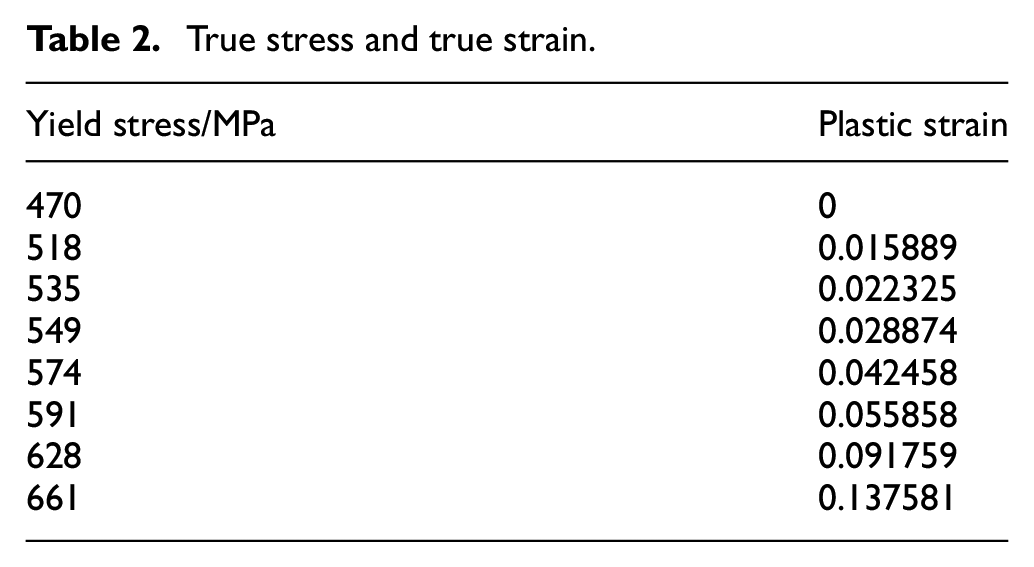
The true stress and true strain values are shown in the following Table 2 38 :
True stress and true strain.
Set the analysis step type, use nonlinear static analysis in this analysis, and turn on geometric non linearity. Set the Increment Type to Auto, the Maximum Increment Step to 100, and the Initial Increment to 0.01.
Defining contact and coupling points: The contact algorithm uses a master-slave contact algorithm: one surface is the master surface and the other surface is the slave surface. When two bodies come into contact, detect penetration and impose contact constraints according to the constraint augmentation method (dynamics or penalty function). Since the objects analyzed in this paper are all contact models, it is necessary to set a reasonable contact surface. Contact element-based contact and surface-based contact are the two basic contact types in Abaqus. Among them, based on surface contact is a widely used type, and the method of surface contact is also adopted in this paper. Set up the tangential mechanics behavior with a friction coefficient of 0.2. Considering that a concentrated force needs to be applied in the load setting, it is necessary to set the coupling point, that is, the node that needs to be loaded is coupled to a point. Establish a coupling point at the center of the upper plane of the upper cylinder, as shown in Figure 11. Normal load and tangential forced displacement act on this coupling point respectively.
Coupling point.
Apply boundary constraints: the lower cylinder is fixed on its lower plane, and the nodes on the lower plane of the lower cylinder are fixed with six degrees of freedom. The upper plane node of the upper cylinder releases the normal and tangential movement degrees of freedom, and the remaining four degrees of freedom are fixed. Since the coupling point has been set in advance in the above steps, the normal load is then applied at the coupling point. The tangential direction is applied by means of forced displacement. The schematic diagram of the contact model constraints at different angles is shown in Figure 12.

Schematic diagram of contact model constraints for different angles: (a) 45°, (b) 60°, and (c) 90°.
FEA results
The von-Mises of the contact model at the interface are shown in Figure 13. The stress value of the contact model is larger at the contact location and increases with the normal load. The red area represents the point where the stress is at or slightly above the yield stress, which means plasticity occurs there. However, for most of the interface, the deformation is elastic.

von-Mises stress distribution for the normal model: (a) P = 10 kN, (b) P = 20 kN, and (c) P = 30 kN.
Figure 14 shows the stress distribution contours of the contact model under different tangential displacements. It can be seen from the figure that the contact model exhibits obvious sliding during tangential contact. The stress distribution of the upper and lower contact models is also not uniform. At the same time, as the tangential displacement increases, the contact stress also increases.

von-Mises stress distribution for the tangential model: (a) U = 0.1 mm, (b) U = 0.15 mm, and (c) U = 0.2 mm (P = 30 kN).
Figure 15 is a contour map of plastic deformation in the contact area. As can be seen from the figure, as the tangential displacement continues to increase, the plastic region becomes larger and larger. The yielding of the material begins to occur first around the perimeter of the central area of the contact surface, and the plastic region expands from the perimeter to the center. This shows that there is an elastic region in the central region of the contact surface, but with the increase of tangential displacement, the elastic region becomes smaller and smaller until it disappears completely. Figure 16 is the tangential displacement cloud diagram. It can be seen from the figure that the center of the contact surface is the place where the tangential displacement is the largest. Due to the stiffness of the material itself, the tangential displacement is distributed in an annular gradient on the contact surface.

Plastic deformation in the contact area: (a) U = 0.1 mm, (b) U = 0.15 mm, and (c) U = 0.2 mm (P = 30 kN).

Tangential displacement of contact area.
The hysteresis curves of the cylinder contact model composed of equations (14), (24), and (25) are verified by FEA. Here, the cylinder hysteresis curve model of a fretting period is verified, and three angles of 45°, 60°, and 90° are verified respectively, where P = 30 kN. The results are shown in Figure 17. Each of the three colors of the theoretical solution and the simulated solution in the figure represents the three processes of loading, unloading, and reloading, respectively.

The theoretical solution of the hysteresis curve compared with the FEA value (P = 40 kN): (a) 45°, (b) 60°, and (c) 90°.
According to Figure 17, the FEA solution of the hysteresis curve corresponds well with the theoretical solution. During the loading phase, the tangential displacement increases with the tangential load while the tangential stiffness gradually decreases. During the unloading phase, the tangential displacement decreases with the tangential load. By comparing the crossing angles of three axes (45°, 60°, and 90°), it can be seen that the axis crossing angle also affects the tangential displacement. The axis crossing angle increases while the tangential displacement decreases. This means that the tangential stiffness decreases as the axis crossing angle increases, which corresponds to equation (17). Moreover, the area of the hysteresis curve increases with the axis crossing angle of the paraboloid contact model, which means greater energy dissipation.
Numerical results and analysis
The effect of different parameters on the hysteresis curve of the cylinder contact model is shown in Figure 18. Figure 18(a) represents the effect of the friction coefficient on the hysteresis curve. The area of the corresponding hysteresis curve is increased with the friction coefficient, which also means greater energy dissipation. This also shows that a lower friction coefficient decreases the model’s ability to absorb energy. The influence of the axis crossing angle on the hysteresis curve is shown in Figure 18(b). The difference between the area of the hysteresis curve and the value of energy dissipation does not differ by much with an increase in the crossing angle. However, during the tangential loading stage, the tangential stiffness is decreased with an increase in the axis crossing angle. This is because a larger angle lowers the contact area between the corresponding models, which in turn increases the contact stiffness. Figure 18(c) represents the effect of normal load on the hysteresis curve. When the tangential displacement is controlled, a higher normal load increases the area of the hysteresis curve, that is, energy dissipation is increased. The greater the normal load, the greater the friction load under the same coefficient of friction. In other words, the same displacement will naturally require more energy to slide.

Effect of different influencing factors on the hysteresis curve: (a) friction coefficient, (b) axis crossing angle, (c) normal load, and (d) Young’s modulus of material.
Figure 18(d) is the effect of different materials on the hysteresis curve. It can be seen that when the materials are carbon steel and copper, the area of the hysteresis curve is not much different. When the material is aluminum, the area of the hysteresis curve is larger relative to the other two materials, which means greater energy dissipation. When the materials are different, the tangential stiffness changes in the loading stage are more obvious.
The effect of different parameters on the energy dissipation for each cycle is shown in Figure 19, which corresponds to the area of each cycle in Figure 18. According to the figure, friction coefficient, axis crossing angle, normal load, and cylinder radius all affect energy dissipation. Two different parts are present in each energy loss curve: the non-linear part corresponding to low tangential displacement and the linear part corresponding to the higher tangential displacement. For low tangential displacement, the contact model of two cylinders will not slide. It will, however, remain in a local stick-slip micro-movement state. Since the degree of sliding in the local stick-slip state is limited, the energy dissipation is lower than the macro-slip state. The nonlinear relationship between energy dissipation and tangential displacement is derived from equation (23).

Influence of different parameters on energy dissipation during each cycle: (a) friction coefficient, (b) axis crossing angle, (c) normal load, and (d) radius.
According to equation (24), the relationship becomes linear in the macroscopic slip state. Since the maximum tangential force remains the same, an additional increase in the displacement will add a rectangular area for energy dissipation. Therefore, maximum tangential load determines the slope of the linear energy loss range. The hysteresis curve also changes from an ellipse to a parallelogram.
The hysteresis curve model and energy dissipation model obtained from this model can be applied to both macroscopic mechanical structures and microscopic contacts (e.g. the KE model proposed by Kogut and Etsion 39 and the BKE model proposed by Brizmer et al. 40 ). On specific application objects, we will continue to explore in the follow-up research.
Comparative analysis with other models
A comparison of the cylinder contact model with other contact models is shown in Figure 20. The tangential displacement is relatively small. Therefore, all models are in a local stick-slip fretting state. The CFC model was proposed by Burwell and Rabinowicz. 41 The CED model was proposed by Chang et al. 42 Tangential displacement increases with tangential load. However, its tangential stiffness is reduced compared to the cylinder contact model. In addition, the area of the hysteresis curve is also smaller than that of the cylinder contact model. This shows that the CFC model and CEB model are also less capable of absorbing energy compared to the cylinder contact model.

Comparison of hysteresis curve for the cylinder contact model with: (a) CFC model, (b) CEB model, (c) KE model, and (d) BKE model.
The KE model was proposed by Kogut and Etsion. 39 The BKE model was proposed by Brizmer et al. 40 As the maximum tangential load increases, the fretting loop becomes narrower, eventually resembling a line. This also indicates a lower ability to absorb energy. This phenomenon is reasonable because the frictional load acts through a tangential equilibrium mechanism. An increase in the coefficient of friction results in a corresponding increase in the friction load. It is assumed that when the friction coefficient is large, the corresponding friction load will become larger. In this way, the contact in the contact area becomes viscous and no relative displacement occurs. If the contact between the contact models is fully adhered, no energy is consumed. Therefore, a narrow hysteresis curve appears. In addition, the tangential stiffness of the KE model and the BKE model during the tangential loading and unloading cycles is also higher than that of the parabolic model.
Conclusions
Micro-slip is a phenomenon that occurs between contacting surfaces when a frictional load smaller than that required to produce macro-slip is applied to the contacting surfaces. Existing cylinder contact models mainly focus on the study of parallel cylinders and crisscross cylinders. Therefore, this paper proposes a micro-slip model based on the contact model of cylinders with different axis crossing angles. The three processes of loading, unloading and reloading of the model are mainly modeled theoretically, and the model of its hysteresis curve is obtained. The analytical formula for the energy dissipation of a single hysteresis curve is also given. This model remains in the theoretical modeling stage and has not been applied to specific mechanical structures such as gears or roller bearings. In the follow-up research, the theoretical model will be combined with the actual mechanical structure to solve specific problems. The model is modeled by the finite element software Hypermesh, and Abaqus is used for FEA. The material of the deformable cylinder is carbon steel. Draw some conclusions:
During the loading phase, the tangential displacement increases with the tangential load while the tangential stiffness gradually decreases. During the unloading phase, the tangential displacement decreases with the tangential load.
The axis crossing angle affects the shape of the hysteresis curve and energy dissipation. At the same time, the coefficient of friction, normal load, material properties and radius all affect it.
The maximum contact stress occurs at the contact site. Material yielding occurs first below the contact surface and gradually spreads toward the surface. On the contact surface, the plastic area expands from the periphery to the central area, forming an annular area. Finally, as the tangential displacement increases, the plastic region extends to the entire surface.
The cylindrical contact model is based on different axis crossing angles. It can be applied to the study of different angles in the gear contact process, and to evaluate the micro-slip state in the gear contact process. At the same time, the cylindrical contact model is a cylinder, which can provide a reference for the micro-slip hysteresis curve models of other cylindrical contact models.
The model proposed in this paper gives theoretical formulas for the loading and unloading process, as well as analytical solutions for energy dissipation in the local slip stage and the macroscopic slip stage. The results are normalized and the model can be applied to macroscopic contacts such as gears and bearings. In addition, since the deformation process and load curve of the contact model are given, it can also be applied to micro-contacts (such as bonding surfaces).
Footnotes
Handling Editor: Chenhui Liang
Declaration of conflicting interests
The author(s) declared no potential conflicts of interest with respect to the research, authorship, and/or publication of this article.
Funding
The author(s) disclosed receipt of the following financial support for the research, authorship, and/or publication of this article: This work was supported by the National Natural Science Foundation of China (Grant No. 51875009) and the Natural Science Foundation of Beijing Municipality (Grant No. 3162005).
Data availability statement
The data used to support the findings of this study are included within the article.