
Abstract
In a planetary gear set with an elastic ring gear, there are several pairs of flexible internal meshing simultaneously. The interactions between them are often ignored when considering their mesh stiffness. This study is devoted to investigating the effect of the number of equally spaced planets and the number of fixed supports of ring gear on mesh force and loaded-static transmission error (LSTE) as well as related mesh stiffness through a 2D system-level finite element model. This model is first validated by the comparison with the traditional potential energy method (PEM) when the ring gear is fully fixed. Then taking the number of planets and fixed supports as variables, 16 sets of analyses are conducted. Mesh force and LSTE extracted from the model, together with the mesh stiffness derived by them, are analyzed and concluded in the time domain and/or frequency domain. It is demonstrated that the number of planets has a certain impact on the ring-planet mesh stiffness. In terms of the number of planets and fixed supports, planetary gear systems can be classified into three categories according to the distinctive behaviors of mesh force and LSTE in the time domain and frequency domain.
Introduction
Owing to its compactness, large transmission ratio, and high power density, planetary gear sets are implemented in every aspect of the industry. Numerous lines of research on their properties follow for better insights and performance enhancements, which may cover kinematic calculation, static and dynamic modeling, condition monitoring, fault diagnosis, etc. As one of the inherited internal excitations of gear pairs, mesh stiffness characterizes those properties to a large extent.
The gear mesh stiffness is the resistance of gear teeth to the deflection induced by mesh forces, generally varying with the contact point and rotation angle of a gear pair, and can be obtained numerically or experimentally. The former is frequently presented in the literature while the latter is mostly used for empirical studies, validation of numerical models, or as monitoring techniques 1 and is relatively scarce to see. Some studies focus on the estimation of mesh stiffness of sound or defective gear pairs using analytical expressions,2–6 in which the PEM plays a crucial role. To pursue a high-precision description of mesh stiffness, the finite element method (FEM) is adopted widely.7–10 For balancing computational time and errors, hybrid methods, namely analytical-FE models are proposed.11–14 The literature listed above exhibits abundant contents that can be excavated since an accurate and rapid acquisition of mesh stiffness in a pair of gears has never been an effortless issue.
Differing from a pair of gears in meshing, a three-planet planetary gear set, usually regarded as the simplest structure, have six pairs of meshing in different mesh phases simultaneously, which means a rather complicated structure should be modeled if one wants to investigate the multi-mesh system. Chen and Shao 15 incorporated the mesh stiffness of sun-planet and ring-planet branches into the dynamic model of a one-stage planetary gear set to investigate the effect brought by tooth root crack in the ring gear. The presence of this failure will not only decrease the mesh stiffness but also generate plentiful sidebands around the fundamental mesh frequency and its harmonics. Liang et al. 16 obtained mesh stiffness curves of a planetary gear set in variable kinematic configurations by appropriately phasing each sun-planet or ring-planet meshing. Then a crack propagation model was seeded in the sun gear and planet gear to explore the rules in the mesh stiffness fluctuation. 17 A similar approach was employed to evaluate the influence of tooth surface wear on mesh stiffness of planetary gear set as well. 18 Considering the nonlinear contact stiffness and the addendum modification coefficient, Dai et al. 19 compared the results of mesh stiffness calculation under different loading torques with experimental measurements based on the strain gauge technique. In these studies, meshes in a planetary gear set are simply regarded as an aggregation of several single external or internal meshes so that the mesh stiffness of each gear pair determined by PEM can be assembled to represent the overall mesh stiffness as long as the mesh phases are integrated. However, things may change when the deformable property of components is combined into modeling, especially for the cases of flexible design of planet carriers and ring gears.
Considering the flexibility of planetary gears is bound to add more complexity but delicacy to mathematical models. Abousleiman and Velex 20 introduced deformable ring gears by using 2D beam elements and 3D brick elements, respectively, and proposed hybrid analytical-FE models that internally calculate dynamic excitations like mesh stiffness and transmission errors (TE). They found that ring gear flexibility modifies static load distributions and critical tooth speeds on internal meshing. Together with the flexible ring gear, they then discretized planet carrier as well and claimed that the contributions of the deflections of planet carrier to tooth load distributions do not seem to be as vital as those of the ring gear. 11 As the component that usually has the largest size but with the thinnest rim in a planetary gear set, deformable ring gear has gained extensive concern.
Due to the contradictive requirements, the design of ring gear is often a challenge. On the one hand, the ring gear should be stiff enough to sustain the load applied to the teeth and supports. On the other hand, it should have as small volume or mass as possible to meet the demand for lightweight design by decreasing the thickness of the ring gear rim, especially in the aerospace and automobile industry. Besides reducing mass, adding gear flexibility through reducing rim thickness was reported to have the ability to compensate for certain manufacturing errors and improve load sharing. 21 Thus, a series of studies around flexible ring gear arise in the last two decades. Kahraman et al. 21 used an analytical-FE model to investigate the bending stress history of sun, planet, and ring gear, indicating that when the gear rims are rather thin a deformable body analysis is necessary for predicting bending modes of rims and modes of the whole planetary gear set. Wu and Parker developed a model describing rings on a general elastic foundation 22 and studied the modal properties of planetary gears having equally spaced planets and flexible ring gear through perturbation analysis. 23 Then Parker and Wu 24 used the same model to study the possible parametric instabilities of planetary gears. These parametric instabilities were classified into three modes and specific instability existence properties were derived, with which potential vibration problems can be eliminated by choosing appropriate gear tooth numbers. A mesh stiffness model of internal gear pairs coupled with uniformly distributed Timoshenko beam theory was put forward by Chen and Shao. 25 The effects of the support type, ring gear rim thickness, and the number of supports on the ring gear toward internal mesh stiffness were investigated. Hu et al.26,27 incorporated a 2D FE model of ring gear rim into an innovative planetary gear set load distribution model, capturing the effects of the flexibility of ring gear on the quasi-static load sharing. It was shown that the flexibility in the ring gear rim promotes planetary load sharing when having manufacturing errors. In short, the integration of flexible ring gear upgrades traditional mathematical models and enhances people’s comprehension of the characteristics of planetary gears.
In a review 28 of dynamics and vibrations of planetary gear, the impacts of component elasticity on system vibration properties were summarized and some correlations between root stress and the number of modal indexes of the bending mode in the ring gear were shown. But the research on system-level parameters of planetary gear sets toward peculiarity of mesh stiffness is seldom to see. Refs.25,29,30 used analytical, FEM, and analytical-FE methods to cope with the determination of flexible internal mesh stiffness, respectively, representing mainstream approaches in this field. However, it might be thoughtless if these types of internal mesh stiffness are directly applied to replace the ring-planet mesh stiffness of a planetary gear set since the coupling effect between multiple ring-planet branches and the number of planets have the potential to influence the behavior of each ring-planet branch. Unfortunately, to our knowledge, a system-level model exploring the flexible internal mesh stiffness of a planetary gear set is still lacking. Motivated by Liang et al. 10 a system-level FE model is developed to investigate the mesh stiffness, mesh force, and LSTE of ring-planet branches in flexible planetary gear systems. The effectiveness of the model is validated by the comparison of mesh stiffness with the traditional PEM when the ring gear is fully fixed. Taking the number of planets and equally spaced supports as variables, 2D FE analyses are performed. Variations of mesh stiffness, mesh force, and LSTE reveal the influence on mesh stiffness brought by the number of planets and show that planetary gear systems can be divided into three categories according to their behaviors in the time domain and frequency domain. These discoveries are believed to deepen our understanding of planetary gears with flexible ring gears and their condition monitoring or fault diagnosis.
System-level mesh stiffness model of planetary gear sets
Mechanism of mesh stiffness calculation in FEM
Mesh stiffness of a gear pair can be calculated through either rectilinear mesh stiffness or torsional mesh stiffness. Rectilinear mesh stiffness is the ratio between a mesh force and corresponding displacement and is defined along the line of action. Torsional mesh stiffness is defined by the ratio of the applied torque and the TE. They are suitable for different occasions but related to each other.
As is shown in Figure 1, an internal gear is meshing with an external gear at the moment of the start of the double teeth mesh area. To emphasize the contact status, the scenario is depicted by employing a stress nephogram. Contacts between gears take place on the line of action, along which resultant mesh forces determine their directions.

An internal gear pair in the double teeth mesh area.
Based on Liang et al., 10 the rectilinear mesh stiffness of a pair of gears regardless of the number of pairs of teeth in meshing can be concluded in the form of potential energy:

where Fi denotes the gear mesh force between the ith tooth pair, and δ1i and δ2i denote the tooth deflections of the ith tooth pair along the line of action. This way may bring some inconvenience in the post-processing of FEM so that it is far from related practical application in most studies.
Equation (2) describes torsional mesh stiffness according to its definition. T denotes the torque applied to the gear and TE a denotes the angular form of TE.

TE is the difference between the perfect position (unmodified, geometrically perfect, and infinitely rigid gears) and the actual position of a gear. 1 Equations (3a) and (3b) represent its angular form and linear form, respectively.


where θi is the rotational angle of gear i, and rbi is the base radius of gear i, as seen in Figure 1 (rb2 is omitted for its oversize dimension). Notice that the direction of θi should be consistent with the direction that the gear i expected to be. When considering the mesh stiffness calculation, the TE under no-load condition (induced by manufacturing errors) should be removed from the total TE so that in equation (2) the deflection involved is purely elastic.
Equation (4) describes rectilinear mesh stiffness in the form of TE l . 1 F denotes the force applied to the gear and can be regarded as the summation of gear mesh forces between multiple tooth pairs.

The relationship between kt and kl can be deduced as follows:

Variables listed in equation (5) will be used in this study because of their easier accessibility in FEM. Under ideal conditions, FE analysis is supposed to be performed at every meshing location of a gear pair in a certain range for obtaining a precise curve of mesh stiffness. To reduce the time consumption, an appropriate length of rotation step must be chosen during the analysis as long as the accuracy requirements are satisfied.
Model construction
Pure FEM has a good calculation accuracy in the determination of mesh stiffness. It can be implemented in two ways according to Ma et al., 31 including FE models with contact analysis and FE models by applying contact load. The number of pairs of teeth in meshing and interactions in/between multiple meshes in planetary gears, especially with flexible design, cause unequal load sharing in sun-planet and ring-planet branches, making contact loads unpredictable. Therefore, FE models with global geometric modeling and contact analysis are essential, which naturally emphasizes the necessity of a system-level model again.
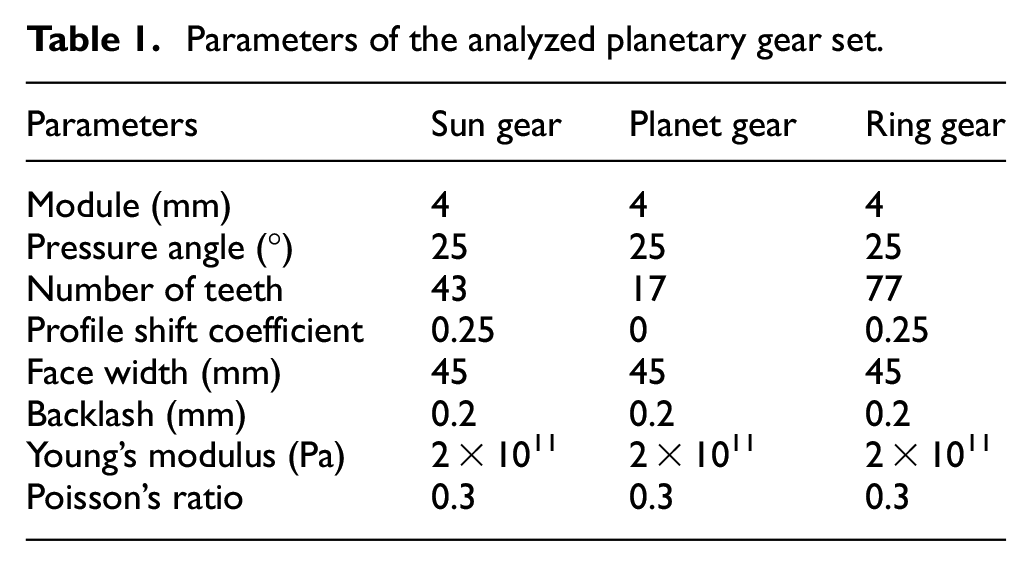
In this paper, we take a planetary gear set with three–six equally spaced planets under three–six fixed supports that are equally spaced on the ring gear into FE analysis based on ANSYS® Workbench. In other words, the test matrix for FE analyses consists of 4 × 4 = 16 individual analyses. Parameters of each component in the analyzed planetary gear set are listed in Table 1. Figure 2 exhibits four planetary gear sets whose number of planets is equal to the number of fixed supports. Since the ratios of (Zs + Zr) to the numbers of planets, that is, 3, 4, 5, and 6, are integers, the planets can be accommodated with equal distance. For highlighting the differences brought about by flexible ring gear, a relatively thin thickness of the ring gear rim is set at 5.2 mm. Torque is anticlockwise applied to the sun gear and its value is marked in Figure 2, while the ring gear is fixed through several fixed supports where the description of this kind of boundary condition can be found in Parker and Lin. 25 Every branch of ring-planet is supposed to carry the identical nominal load so the mesh stiffness results can be reasonably compared when the only variable is the number of planets. As seen in the three-planet planetary gear set from Figure 2, planets are clockwise numbered from the top one as P1, P2, P3… Among those planetary gear sets, P1 keeps its position settled and is selected as the reference to phase other planets. Referring to Parker and Lin 32 for the assembly of planets considering mesh phase. The mesh position of P1 is the moment of the beginning of the double teeth mesh area with ring gear and is already shown in Figure 1. Floating effects in central components are temporarily ignored in this paper and will be addressed in the future since a fundamental comprehension should be first formed as basic. Consequently, hub bores (inner cylindrical surfaces) of sun gears and planets are supported cylindrically, indicating that only tangential movements around the gear shafts are allowed.
Parameters of the analyzed planetary gear set.
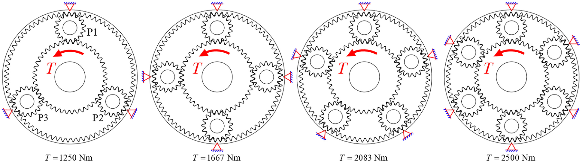
Planetary gear sets with equal numbers of planets and fixed supports.
2D FE analysis considers both economy of time and calculation demands of mesh stiffness by spur gears. Accurate solutions to stress and strain are needless so the modeling along the direction of gear thickness can be omitted. Solutions of averaged forces, moments, and displacements will be output, which is exactly needed for the mesh stiffness calculation. To realize these objectives, after geometric modeling and importing to ANSYS® software, the 2D behavior of analyses should be selected as Generalized Plane Strain. Figure 3 shows the mesh structure of 2D FE analyses, where all the geometries are partitioned by quadratic triangles. Elements near the surfaces of gear teeth and hub bores are refined for better performance of contact analysis and data extraction.

The detail of the mesh structure of P1.
In the post-processing stage of FEM, deformation and force will be extracted for subsequent calculation. Cooley et al. 8 used the FE software Calyx to analyze a pair of spur gears. Absolute tangential deflections of the gear and pinion were calculated at multiple radii from the hub bore diameters to the diameters near the tooth root. It was shown that the tangential/angular deflections, and so the resulting mesh stiffnesses are insensitive to the radii. Without loss of generality, the tangential deformation at the radius of the rhub (see Figure 1) will be adopted here for its convenience. But in the proposed model, this deformation is not a constant because the whole model is modeled elastically without any rigid elements on the hub bore surface. In the mesh stiffness models of Liang et al. 10 they found that the angular deflection of the end surface circle is likely to follow a cosine curve, and the minimal angular deflection acquired from the best fitting curve based on the least-squares fitting method will give very good results of equation (3a). We integrated this method into our model and received satisfactory results as well in the stage of model validation, which will be displayed in the next section. In this scenario, the displacement obtained at each rotation angle, which represents the relative displacement of the output gear to the input gear under an applied load, is referred to LSTE. 1 Concerning the force extraction, it is obvious that there are no forces nor moments applied manually on planets or ring gears. Moments are explicitly loaded on sun gears and transmitted through gear bodies and contact elements. Whereas ANSYS® Workbench allows for inserting a probe object to calculate force reaction in contact regions defined in advance, regardless of the number of pairs of teeth in meshing. In this way, the total mesh force of each ring-planet branch can be extracted.
The mesh stiffness of a ring-planet branch is expressed as:

where Fm, δhub are the total mesh force of this ring-planet branch and tangential deformation calculated from Ref., 10 respectively. rb1 and rhub can be seen in Figure 1, where θ2 = 0 because of the fixed constraints of the ring gear. That is to say, in equation (3b) TE l = rb1θ1. It is worth mentioning that in this paper the calculation method belongs to the average slope method according to Cooley et al. 8 In this method, the mesh stiffness is the total mesh force divided by the mesh deflection and is appropriate for static analyses.
Model validation
An additional FE analysis is performed to validate the effectiveness of the aforementioned model. The flexibility of ring gear is removed by fully constraining its outer diameter thus the consequence can be compared with the output of the traditional PEM. In Refs.,3,33–35 this method had already been verified through FEM, showing prominent applicability and accuracy. Hence, we may as well regard it as a criterion for assessing a mesh stiffness model. Notice that apart from bending stiffness, shear stiffness, axial compressive stiffness, and Hertzian contact stiffness, only the fillet-foundation stiffness of external gear is considered in the PEM.
A model of a three-planet planetary gear set is put into the calculation. For convenience, a mesh stiffness segment of ring-planet 1 branch that represents a certain tooth from the moment of entering into meshing to the moment of exiting the meshing is selected for the validation. Torque of 1250 Nm is anticlockwise applied on the sun gear. Figure 4(a) shows the tangential deformation of the hub bore surface of P1, in the form of a deformation nephogram. Figure 4(b) plots this tangential deformation and corresponding best-fitting curve using circumferential angle as a variable (the data point with minimum value is selected as the reference point with zero polar angles). This deformation mode is already studied in Liang et al. 10 and thus qualifies itself to engage in the mesh stiffness model established in the previous section. Figure 5 shows the two mesh stiffness curves of the proposed model and PEM model (the first data point corresponds to the tangential deformation in Figure 4). The PEM model exports a smooth curve both in double and single teeth mesh areas because of its ideal conditions. The stiffness values of the proposed model are slightly fluctuant due to the limited discretization of gears and indeterminacy in iteration. When the contact status of the FEM model suffers from an abrupt change, or some elements become highly distorted, the ANSYS® program will attempt different configurations of contact analysis for convergence and the indeterminacy is therefore embodied. By the moment of altering the number of teeth in meshing, the jumps of stiffness values do not appear to be so immediate as the PEM model’s, which brings about the maximum mesh stiffness difference Δ max = 3.57 × 10⁸ N/m between the proposed FEM model and the PEM model. This might be caused by a phenomenon called extended tooth contact. Owing to the flexibility of teeth, especially under large load conditions, the incoming tooth pair will enter earlier than the theoretical start of contact, and the outgoing tooth pair will leave contact later than the theoretical end of contact. 36 In this case, the contact zone of double teeth is modestly extended compared with the theoretical one. Whereas the loss of contact zone of a single tooth then elevates the average mesh stiffness accordingly. Mesh behavior is consequently changed in this way. But in general, both the shape and magnitude of the two curves are consistent, proving the effectiveness of the proposed model.

Tangential deformation (unit: mm) of hub bore surface of P1: (a) deformation nephogram from ANSYS® Workbench and (b) data points and their fitting points.

Performance comparison between the proposed FEM model and the existing PEM model.
Results and discussions
In this section, the mesh stiffness and the characteristics of planetary gear sets will be first studied in the presence of flexible internal meshing. As the variables of mesh stiffness calculation, mesh force and LSTE are also discovered to reveal the distinctive behaviors associated with the number of equally spaced fixed supports on the ring gear. Therefore, they are of equal importance to the mesh stiffness and deserve a careful investigation.
During the analyses, the relative rotation angle of the planet carrier and ring gear is set as 360° to ensure that the behavior of each other is completely captured. Without loss of generality, the corresponding relative angular velocity can be set as 1 °/s and the abscissa in every undermentioned figure of the time domain is going to be modified as the time of rigid motion, varying from 0 to 360 s. Except for the enlarged views of detail, which have the length of the step of 0.1° in terms of the relative rotation angle of planet carrier and ring gear, the other figures of the time domain are 0.5°. That is to say, for individual analysis, there are 721 data points to solve. Furthermore, a planetary gear set with x planets and y supports will be abbreviated to “xPyS system” for the sake of conciseness.
Mesh stiffness
Although 16 individual analyses have been conducted, we choose a part of them to highlight the typicality of mesh stiffness variation, and they are shown in Figure 6. It is worth noting that some data points in the 6P3S system do not converge because of the abrupt change in the contact area and resultant high nonlinearity, and thus are not plotted in Figure 6(g). The time interval between arbitrary adjacent discontinuous areas seems equal to each other in Figure 6(g), which indicates that during the motions of carriers and planets every certain time interval the high nonlinearity appears. According to the tendency of curves, it can be inferred that the high nonlinearity originates from the contact loss of planets. This situation will be alleviated as the thickness of the ring increases or the torque decreases. Fortunately, the primary shape (high stiffness area) of the mesh stiffness curve has been retained so this failure in convergence is of secondary importance and will not influence our basic judgment of the variation rules of mesh stiffness. Figures listed horizontally represent the results from the ring-planet 1 branch of four planetary gear sets having the same number of planets but the different number of fixed supports, such as Figure 6(a) to (d). Figures listed vertically represent the results from the ring-planet 1 branch of four planetary gear sets having the same number of fixed supports but the different number of planets, such as Figure 6(a) and (e) to (g).
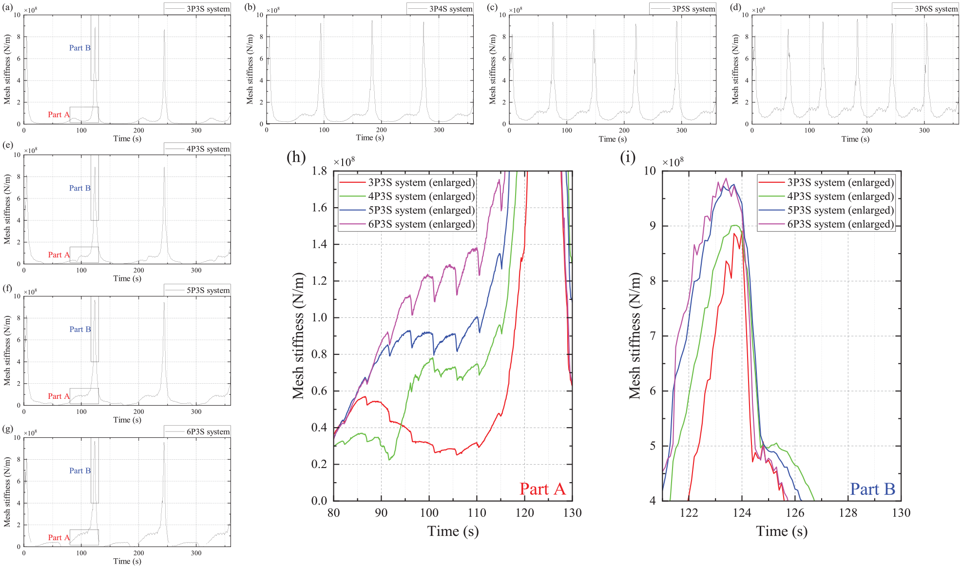
A part of mesh stiffness results that are used for horizontally and vertically comparison, and relevant enlarged viewsof detail: (a) 3P3S system, (b) 3P4S system, (c) 3P5S system, (d) 3P6S system, (e) 4P3S system, (f) 5P3S system, (g) 6P3S system,(h) enlarged view of “Part A”, and (i) enlarged view of “Part B”.
From Figure 6(a) to (h), we can see that through the decreased thickness of the ring gear rim and applying a relatively large torque, the peaks of the curve are more distinct than the fluctuation of mesh stiffness induced by the variable number of pairs of teeth in meshing. Nevertheless, the situations in Refs.29,30,37 are fairly moderate versus the case in this paper. Either is eligible because the level of ring gear flexibility has a great effect on the behavior of mesh stiffness. It is obvious to see that the number of peaks in each figure is equal to the number of fixed supports. But those peaks appear behind the moment when planets pass fixed supports. These time lags are close to the time for a planet like P1 from its initial position to the place where its line of action coincides with a fixed support (corresponds to the maximal stiffness of the ring gear rim). When a peak value presents depends not only on the value of time lag but also on the mesh stiffness value without flexible ring gear, in other words, contact position and number of pairs of teeth in meshing. As a result, it is very normal to see that in a certain figure the peak values are unequal to each other. Figure 7(a) to (d) exhibit the mesh stiffness behaviors of all four ring-planet branches of a 4P5S system. Planets are clockwise numbered and fixed supports are anticlockwise numbered in Figure 7(e). Peaks of mesh stiffness produced by the revolutions of planets are numbered corresponding to those numbers of fixed supports. The results indicate that those peaks with the same number have almost identical amplitude. These amplitudes are only related to the relative angles of planet carrier and ring gear for a certain planetary gear set. Between two peaks, there is a trough corresponding to the low-stiffness area. In three-support systems (see Figure 6(a) and (e)–(g)), the amplitude of the trough is excessively low, suggesting that the flexibility along the line of action is too large to sustain the extra load. Under extreme conditions, a ring-planet branch may even be disabled due to contact loss. With the increasing number of fixed supports (see Figure 6(a)–(d)), the width of the trough decreases and amplitude increases, and the fluctuation of mesh stiffness gets more evident and fiercer.

The relationship between the peak values of mesh stiffness and the locations of fixed supports in a 4P5S system: (a) mesh stiffness of ring-planet branch 1, (b) mesh stiffness of ring-planet branch 2, (c) mesh stiffness of ring-planet branch 3, (d) mesh stiffness of ring-planet branch 4, and (e) diagram of numbering of planet gears and fixed supports.
The distinction of mesh stiffness behaviors is shown in Figure 6(a) and (e) to (i) when considering the variation in the number of planets. Overall, the waveforms are similar to each other, including their shape and magnitude. However, there are still differences in detail when they are put together and zoomed in. Figure 6(h) shows the enlarged view of troughs marked as “Part A” in Figure 6(a) and (e) to (g). Four curves exhibit different tendencies but are modulated by mesh stiffness fluctuation with the same frequency and phase due to the variable number of pairs of teeth in meshing. In this time area, the amplitudes of curves elevate with the increasing number of planets. This pattern is only valid for the cases with the three-support ring gear. For a 3P3S system, a segment of ring gear subtending 120° meshes with one planet at any time. Whereas for 4P3S, 5P3S, and 6P3S systems, this number is two, with a smaller distance for two adjacent planets. It means that for a certain planet located in the area shown in Figure 6(h), another adjacent planet that lags will provide extra support to enhance its mesh stiffness. This phenomenon will become more evident as the number of planets grows. As for the cases of four, five, or more fixed supports, concrete analysis is needed for specific situations and will not be repeated in this paper. Predictably, the differences in this area will decrease or even disappear because of the reinforcement of ring gear rim stiffness as the number of fixed supports grows. Figure 6(i) shows the enlarged view of peaks marked as “Part B” in Figure 6(a) and (e) to (g). These peaks can be assumed to emerge at the same time or, to be exact, emerge in succession within a very short period. The peak values are varying with the number of planets, among which the relative error can reach up to 10%. This might be the result of the meshing effect by the adjacent planet that is also simultaneously located between two fixed supports. It is like adding another force to a statically indeterminate beam that was originally subject to a single force. The additional deformation induced by this adjacent planet would influence the contact status of the current planet in turn and thus changes the mesh stiffness behavior mutually. Refs.29,30,37 investigated flexible internal meshing of planetary gear system considering the number of supports, the thickness of ring gear rim, and the flexibility of support, and obtained promising achievements. But if one desires a more precise result of mesh stiffness estimation, the influence of the number of planets must be taken into account, especially in the case of a relatively small number of supports.
In this section, the mesh stiffness in the flexible internal meshing of the spur planetary gear system is studied horizontally and vertically, and its variation rules are summarized in detail. Focus on the impact of the number of planets on mesh stiffness, the underlying mechanisms are given through qualitative analysis. It is necessary to include this impact in research for high-precision modeling since few studies have noticed this issue or only modeled it implicitly.
Mesh force
Since the basic characteristics of mesh force fluctuation are sufficient to be reflected within three-planet systems and it is cumbersome to plot all the curves, only a part of the results will be shown. But all the observations in the frequency domain are going to be listed in a table for summarizing some rules. Corresponding to the mesh stiffness results shown in Figure 6(a) to (d), the mesh forces used in the calculation are depicted in Figure 8. Seen from these curves, we may first have an intuitive sense that mesh force variation exhibits different patterns. In fact, in every figure, the number of peaks (or peaks of envelope line) is equal to the number of fixed supports and the peak values are close to each other. But Figure 8(a) and (d) contain more obvious high-frequency components and low peak-to-peak value while for Figure 8(b) and (c) the opposite is true. This indicates that when each ring-planet branch has an approximate instantaneous mesh stiffness value, the resultant mesh force varies within a small range but with high frequency. According to this feature, setting the average mesh force as a threshold to evaluate the peak-to-peak values so that the mesh force patterns can be divided into two categories, that is, type A like Figure 8(a) and (d), and type B like Figure 8(b) and (c). The average mesh force Fma can be derived as Fma = Z r T s /(N p rb2Z s ), where Ts is the torque applied on the sun gear and Np is the number of planets. In this paper, Fma≈5346 N. In fact, those mesh force curves that are not shown because of limited space follow the same rule. Apart from the preceding three-planet systems, there are 4P4S, 5P5S, and 6P6S systems belonging to type A and others belonging to type B, which is predictable based on the aforementioned analysis.
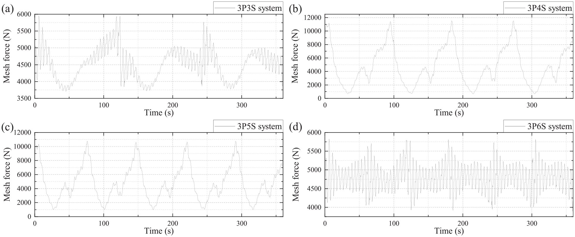
Mesh force curves from ring-planet 1 branches in three-planet systems: (a) 3P3S system, (b) 3P4S system, (c) 3P5S system, and (d) 3P6S system.
Analyses in the frequency domain will better improve our comprehension of mesh force variation. Figure 9 plots four Fourier spectra of mesh force shown in Figure 8. Owing to the great difference in their amplitude, DC components are neglected and the vertical axis is extended as much as possible for ease of viewing. For 3P4S and 3P5S systems, their spectra exhibit abundant low-frequency components with very high amplitude, including fring and fsupport and/or their high order components, where fring and fsupport denote the relative rotational frequency of ring gear and planet carrier (fring = 1/360 Hz in this paper) and planet-passage frequency of fixed supports, respectively. While for 3P3S and 3P6S systems, their mesh frequency fmesh = 77/360 Hz and is relatively outstanding in numerous frequency components. These behaviors are consistent with our intuitive sense of the time domain. On the whole, the amplitude of mesh frequency increases with the increasing number of fixed supports.

Fourier spectra of mesh force from ring-planet 1 branches in three-planet systems (fs = f support ).
Focus on several characteristic frequencies and their harmonics, spectra of mesh force from 16 sets of analyses are interpreted quantitatively and listed in Table 2. On account of non-convergence in the 6P3S system under 2500 Nm torque applied on sun gear, another analysis under 500 Nm is conducted instead to obtain relevant data. In each cell of this table, listed numbers represent the harmonic orders from harmonics that are local conspicuous. The ellipsis and minus sign, if any, represent that observed harmonics of higher orders have been omitted, and there are no corresponding harmonics, respectively. Limited by the number of data points in every set of analyses, the sampling rate (2 Hz) cannot reach high to include excessively high harmonic orders of mesh frequency (greater than 4fmesh) and those numbers of the order are thus listed without ellipsis. From Table 2, we can see that for those systems whose Np and Ns (denotes the number of fixed supports) are coprime, their harmonic orders follow certain rules. The missing numbers of orders of fsupport equal to nNp, where n represents an arbitrary positive integer. For fring, only Ns multiples of fsupport orders exist. Although it is impossible to summarize any rules for fmesh using the results in Table 2, several extra analyses have been conducted for further exploration, in which the sampling rate has been increased to 4 Hz. The results show that the missing numbers of orders of fmesh are equal to nNp as well. This rule is also valid for the next two cases except for the 6P3S system. For systems whose ratio of Ns to Np equals an arbitrary positive integer, they will not have any harmonic orders of fsupport, such as the 4P4S system and 3P6S system, or only have 1 and 2 harmonic orders of fsupport, confined to the 3P3S system. Their mesh force variations in the time domain correspond to type A. For fring, general rules have not yet been discovered to explain the phenomena in Table 2, especially for the 3P3S system, whose orders of fring seem particularly strange. For systems whose greatest common divisor of Ns and Np is neither equal to one nor equal to anyone of Ns and Np, and 6P3S system, the missing numbers of orders of fsupport equal to nkv, where kv represents the ratio of Np to their greatest common divisor (the same below). For fring, only Ns multiples of fsupport orders exist. For the 6P3S system, we speculate that the missing numbers of orders of fmesh are equal to 3n.
Harmonic orders of fring, fsupport, and fmesh of mesh force from all 16 individual analyses.

In this section, the mesh force in the flexible internal meshing of the spur planetary gear system is studied both in the time domain and frequency domain. Most rules about harmonic orders of characteristic frequencies are summarized while others remain unsolved, which calls for further work, whether it be a theoretical study or experimental study.
LSTE
LSTE is converted from δhub at the hub bore surface of a planet gear and can be seen in equation (6). Judged directly by the shape of curves, the patterns of LSTE can be divided into two categories, that is, type A shown in Figure 10, and type B shown in Figure 11. No matter what type a curve belongs to, it is visually periodic (every period may not exactly be the same). The number of periods is equal to the number of fixed supports when a planet carrier rotates 360° relative to a ring gear. The waveform in type A is continuous and simultaneously smoother than that in type B. In every period of the curve of type A, there are double unequal peaks. Either increasing the number of fixed supports or planets will significantly decrease the peak-to-peak value of LSTE within the range of type A. The objective planetary gear systems of type A here coincide with those of type A mentioned in the previous section except for the 6P3S system. Every period of curves in type B varies with the number of planets. For those systems whose Np and Ns are coprime (Figure 11(a)–(c)), the number of peaks in a period equals the number of planets, including a higher peak and Np-1 lower peaks. Besides, when the nominal load of a ring-planet branch keeps constant and adding the number of planets, the fluctuation range of LSTE will decrease with a fairly limited value. But for systems whose greatest common divisor of Ns and Np is neither equal to one nor equal to anyone of Ns and Np, the number of peaks in a period equals to kv, like the 4P6S system (Figure 11(d)) and 6P4S system (not shown here).

LSTE curves of type A: (a) 3P3S system, (b) 3P6S system, (c) 4P4S system, and (d) 5P5S system.

LSTE curves of type B: (a) 3P5S system, (b) 4P5S system, (c) 6P5S system, and (d) 4P6S system.
Figure 12 plots four Fourier spectra of LSTE from three-planet systems. A deformable ring gear with three fixed supports will exhibit great flexibility under the effect of three planets, which can be seen in its LSTE spectrum. Whereas for the cases of four, five, and six supports the rigidity of ring gear is surely enhanced so that the LSTE decreases. Specifically, harmonic orders of characteristic frequencies of LSTE are listed in Table 3. In the table, an asterisk behind a number represents the amplitude of this harmonic receives leap increase. The rest of the rules are the same as the corresponding illustration in the previous section. Differing from the case of mesh force, the LSTE of all 16 sets of analyses has fsupport orders of positive integer multiples rather than a part of them. For fring, there are only Ns multiples of fsupport orders exist. However, the amplitude behavior of LSTE is quite different. For fsupport of a system whose Np and Ns are coprime, leap increase occurs at every Np harmonic order. For the fsupport of a system whose ratio of Ns to Np equals an arbitrary positive integer, the amplitude of the harmonic diminishes as its number of orders increases. For fsupport of a system whose greatest common divisor of Ns and Np is neither equal to one nor equal to anyone of Ns and Np, and 6P3S system, leap increase occurs at every kv harmonic orders. As for fmesh and its harmonic orders, they are not listed in Table 3 for general rules have not yet been discovered. Nevertheless, the amplitude of fmesh remains fairly consistent in all the sets of analyses.
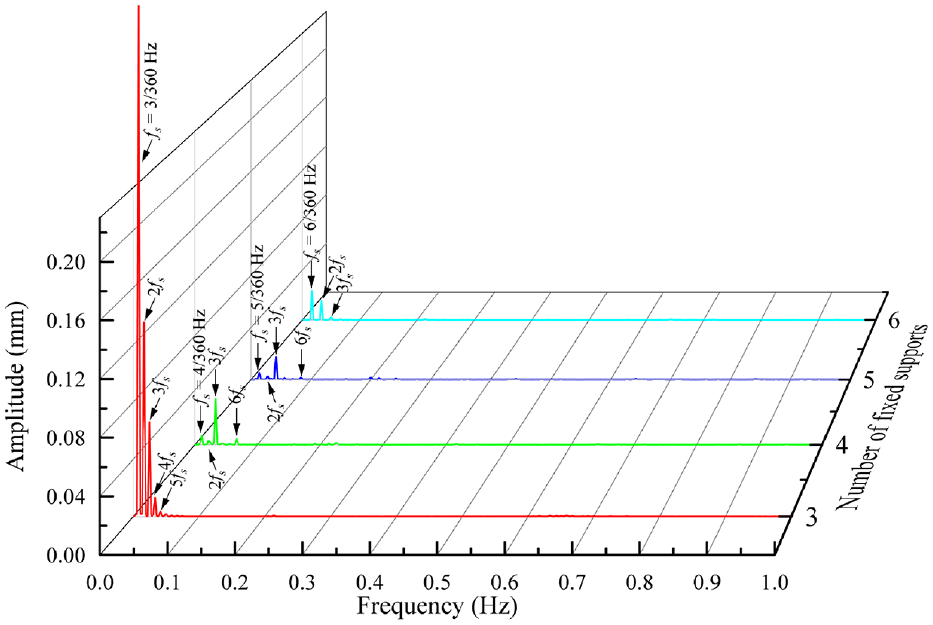
Fourier spectra of LSTE from ring-planet 1 branches in three-planet systems (fs = fsupport).
Harmonic orders of fring and fsupport of LSTE from all 16 individual analyses.

Represents the amplitude of this harmonic receives leap increase.
In this section, the LSTE in the flexible internal meshing of the spur planetary gear system is studied both in the time domain and frequency domain. Classifications on planetary gear sets according to the mathematical relationship of Np and Ns exhibit a visible degree of uniformity with the results of the previous section.
Conclusions
Considering the interactions between multiple sun-planet-ring branches, this study develops a system-level FE model to evaluate the mesh stiffness, mesh force, and LSTE of flexible internal meshing in spur planetary gear sets. Based on the analysis of the time domain and/or frequency domain, major conclusions are summarized as follows:
The number of planets does have a certain influence on the mesh stiffness of ring-planet branches. To be specific, whether a planet and its adjacent planets locate simultaneously at a segment of ring gear that is divided by two fixed supports is of great importance to the mesh stiffness at the current mesh position. This effect must be considered in the accurate modeling of planetary gear sets.
According to the behaviors of mesh force and LSTE in the time domain and frequency domain, planetary gear systems can be divided into three categories in terms of Np and Ns, that is, (i) Np and Ns are coprime. (ii) The ratio of Ns to Np equals an arbitrary positive integer. (iii) The greatest common divisor of Ns and Np is neither equal to one nor equal to anyone of Ns and Np. Every kind of planetary gear system shows distinctive behaviors in harmonic orders of characteristic frequencies that are easy to summarize.
This study about the mesh stiffness, TE, and mesh force of planetary gears with flexible ring gears is believed to contribute to the development of their condition monitoring and fault diagnosis. There are mainly two types of approaches for gear fault diagnostics: data-driven-based methods and physical model-based methods. 38 Lumped parameter modeling is usually used in the model-based methods to acquire the simulated signals, which requires the predetermined mesh stiffness to be input as the model parameter. The simulated signals can improve the understanding of the vibration responses and enrich the database of fault diagnosis of planetary gearboxes. 39 TE is recognized as one of the best measurements for gear condition monitoring and quality control, especially when measured at low speed. 40 Apart from the vibration signals, researchers have also developed models for condition monitoring and fault diagnosis of planetary gears by using TE signals.41,42 Although the mesh force cannot be directly measured, some investigations still studied the mesh force behavior43,44 because an understanding of gear dynamics and an accurate evaluation of the mesh force are essential for the design of planetary gears with low vibration and low noise. 44 Therefore, a comprehensive estimation of TE and mesh force is necessary both in the time domain and frequency domain when studying the planetary gears involved in this paper.
Admittedly, there are still some phenomena that are hard to explain and more effort should be put into solve, especially for harmonic orders of mesh frequency in LSTE, and behaviors of 6P3S systems or systems whose ratio of Np to Ns equals a positive integer that is greater than one. However, the latter is not that important because this situation is rare in practical application. In the future, an analytical model including multiple internal meshing is expected to establish for quantitative analysis with great depth.
Footnotes
Acknowledgements
The authors would like to acknowledge the support of the State Key Laboratory of Fluid Power and Mechatronic Systems and the Key Laboratory of Advanced Manufacturing Technology of Zhejiang Province.
Handling Editor: Chenhui Liang
Declaration of conflicting interests
The author(s) declared no potential conflicts of interest with respect to the research, authorship, and/or publication of this article.
Funding
The author(s) disclosed receipt of the following financial support for the research, authorship, and/or publication of this article: This study was funded by the National Natural Science Foundation of China (Grant No. 51275453).