
Abstract
Martial arts and fight sports are mostly based on exchanging the punches and kicks that often result with injuries of face, skull bones, and neck vertebrae. One of possibilities to reduce number of injuries in athletes who deal with martial arts is development of new materials and improvement of designs for helmets used in sport fights. In order to experimentally analyze impact forces and simulate conditions during different fight punches mechanical installment was made. Aramis system is used to measure the displacement fields and the distribution of deformations which occur on the neck over the entire analyzed area based on the correlation of digital images. On this manner better understanding of behavior of both materials and structures during the action of the impact forces and loading is obtained. This information can further be used in researches related to the development of helmets used in martial arts which would influence reduction of values of neck deformations in athletes.
Introduction
Martial arts and combat fight sports, such as boxing, kickboxing, taekwondo, karate, kung fu wushu, muay thai boxing, and related sports, are based on the exchange of punches that often result with injuries of face, skull bones and neck vertebrae, different concussions, etc. All these injuries are a consequence of impact forces that lead to disruption at the tissue level, which further leads to plastic deformations of the tissues. Several studies assessed and compared the types and frequencies of injuries in different combat sports, and they have shown the frequency of head and neck injuries due to fighting in martial arts. A study conducted by Alizadeh et al. 1 showed that the incidence of head injuries was 57.06% and 38.27% of neck injuries, respectively, while Boostani et al. 2 reported 64.6% head injuries and 57.9% neck injuries. Lystad et al. 3 concluded that in martial arts the most frequent injured areas in the body are head and face (66.8%–78.0%), and that wrist and hand are following (6.0%−12.0%). Boxing, karate, taekwondo and kickboxing are having the highest incidence of head and face injuries, as well as neck injuries.4–10 Stamboloy and coworkers presented results of 20 years lasting study which comprised 2845 head and neck injuries in different martial arts, where it was also concluded that anatomical region under the most impact is head with 39.7% injuries, followed with face 31.5%, and neck 15.2%). 11
The most often performed manual techniques in sport fights are: gyaku-tsuki-counter-punch (i.e. last direct) which is also the most common punch (65%–72%), kizami-tsuki fore-punch straight in the front (i.e. front direct) which is present in 11%–22%, ura-tsuki (i.e. uppercut) and mavashi-tsuki (i.e. crochet) where share of both punches is 7%–16%.12,13
Which of these punches can potentially cause more serious injuries in the neck area, as well as the head or brain, due to the impartment of forces, appearance of deformities, and significant movements, is the main question. In order to answer these questions, it was necessary to measure the deformations on the neck, as well as the movements of the head which occur for each of these punches, and to compare them.
Several researches have shown different installments for measuring kick or punch forces, and some of them included heavy bag filled with water, 14 measuring system based on accelerometer, 15 accelerators with pressure mapping systems, 16 force plate, 17 measuring system based on strain gauge, 18 and dynamometric punching bag with an embedded accelerometer. 19
Impacts on the head in martial arts were studied for the first time on an anthropomorphic test device Hybrid II crash test dummy which consisted of head and neck mounted to fixed construction. Karate practitioners were punching and kicking the Hybrid II and obtained accelerometer measurements in the 90- to 120-G range indicated that safety-chops (hand protectors) and safety-kicks (foot padding) did not reduce acceleration of the dummy. 20
Studies of high-performance dummy were continued on Hybrid III with defined real biomechanics for testing purposes, and which had a realistic frontal impact response (shown in Figure 1(a) and (b)). Contact force was determined by a biomechanically realistic frontal impact response for both localized and distributed facial loads. Hybrid III head shown anthropometric and inertial properties and the forehead impact response. 21 It provided measurements of force and acceleration at different body regions, which can be further used for calculation of injury risk using operational tolerance data in the form of injury criteria, or injury probability curves. 22

Hybrid III dummy (a) attached to a stand (b) with a fragile foam subassembly. 21
Data on the experimental, mechanical analysis of the impact speed which fighters achieve while punching in sport fights, and their influence on neck and head injuries, are available in a small number of papers. Chadli and colleagues built the system around the torsion bar with set of sensors with goal to measure the maximal force and assessment of the fist acceleration while punching. With it, it was possible to measure also the reaction time, touch time, and interacting time of the fist on the target. 23
The other group of researchers used piezoresistive sensors with the goal to measure the force which is acting on sensors during punches.18,24 Based on those researches, Venkatraman et al. measured the speed and the force generated by a gyaku-tsuki punch from fight attitude on the measurement system, with sensor arrangement particularly chosen based on the extensive finite element analysis (FEA) simulation (Figure 2). With the system that they used it is possible to study kinematics of the arm. Also, they proposed improvements of their system with electromyogram (EMG) signals of a particular muscle group to get the correlation to the function of a punch, or combining their system with an imaging system that has depth sectioning and functional imaging capabilities, and studying the blood flow change and structural damage at the point of contact.

(a) Experimental setup of the system mounted on the wall, (b) schematic circle chart of the system, (c) the principle of operation of the module for measuring the speed of impacts, and (d) fight position when performing impacts. 25
Previous researches have been mainly based on measuring the speed of punches and the impact force produced by fighters while performing manual techniques when punching the head. Parameters such as the weight of the fighter, the amount of muscle mass, the mass and surface of the fist, the training, and the way the punch is performed are variable factors that can directly affect the intensity of the force and the consequences that this force can cause.26,27 Consequences of large impact forces acting on the head and neck are still not sufficiently covered in studies.
Gramling and Hubard examined reduction of the impact force on the neck using a “HANS” (Head and Neck Support) device, which was primarily used in researches covering the motor vehicle accidents. This device takes over part of the shear forces, thus reducing the effect of impact forces on the neck, and also damps the rotation of the head due to accidents that occur in motoring. The aim of this paper was to present the possibility of measuring neck deformations of the experimental model caused by the action of impact forces that occur in martial arts, for different types of impacts. 28
Injuries of the cervical spine
Significant part of injuries during various physical activities, and not so rarely in martial arts, are injuries to the cervical spine and concussions. By their nature, injuries to the cervical spine are very serious, and the degree of injury and permanent consequences afterward can have a great impact on the quality of everyday life. Computational modeling is useful part of injury mechanism studies. With these kinds of models, it is possible to analyze tissue stress and strains by relating spinal cord impact with spinal cord tissue damage. 29
The cause of the injury is a traumatic neck movement that exceeds the physiological threshold of the neck movement, which includes bending, stretching, or shearing (Figure 3). Such injuries occur due to, among the other things, twitching movements of the cervical spine during punches to the head, different falls, traffic accidents etc. Moment of interest in this study is shown in Figure 3(c)).
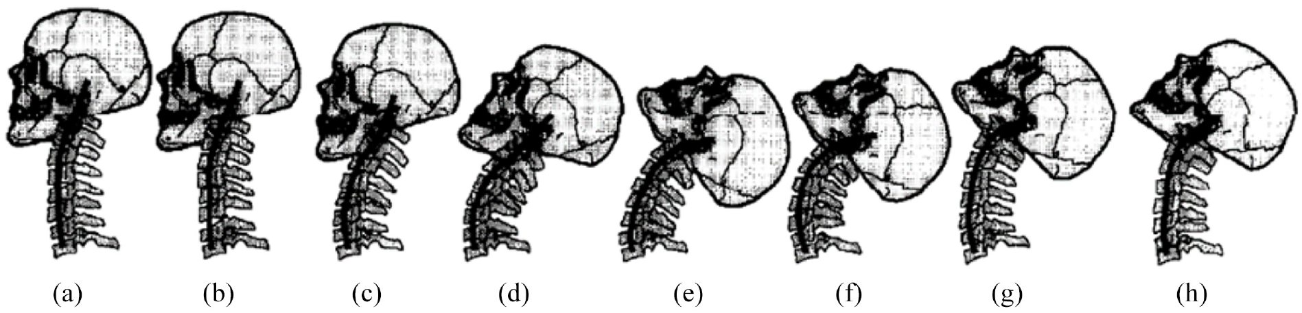
(a) represents the neutral pose, while (b-h) represent head postures on every 25 ms during the occurence of traumatic neck movement. (c) part is the moment when injury happens (addapted according to Panjabi et al). 30
As a consequence of these movements, trauma occurs in the form of soft and hard tissue damage (joints, capsules, ligaments, muscles, nerves, and vertebrae), such as stretching or rupture of tendons, nerves, muscles and ligaments around the cervical spine, as well as sprains of the joints in the cervical spine. Such injuries generally involve lesion of a large number of anatomical structures, which can recover fully or partially, depending on the severity of the injury. Available examination protocols and diagnostics used for observation of damaged structures sometimes are not enough, so possibility of omission is present.
Typical injuries of the cervical spine are whiplash injuries and they occur due to hyperextension of the neck. Hyperextension of the neck results in forced elongation of the cervical vertebrae that causes pressure forces on the structures of the posterior part of the neck and a tightening force on the structures of the anterior part of the neck.31,32 Impact forces that move the head backwards and stretch the neck, after the cartilage on the zygapophysial (facet) joints is completely compressed, so it can often cause damage due to compression. Such damages can manifest itself as a fracture and contusion of the joint, or additional stretching of the anterior structures over their yield point. If the stretching of the anterior structures is extreme, the muscles, ligaments or discs may rupture, as well as the separation of the disc from the ends of the vertebrae can occur (Figure 4).

Sketch of two vertebrae with the direction of the vector of displacement of their movement due to “whiplash” injury. 32
There is a gap in defining the micro-failure mechanisms when different fracture initiations and propagation in human head bones occur for wide range of impact and blunt trauma scenarios, and also how these micro-failure mechanisms develop into macro-fracture types (e.g. depressed, linear, etc.). State of stress at the location where fracture appear influences these micro and macro mechanisms of fractures, which are further dependent on the external loading conditions. Initiation and location of shear, tensile, and compressive dominant fractures could be determined by the resulting state of stress. 33
Based on the data from the mentioned researches, it can be seen that there is a significant problem regarding head and neck injuries in martial arts. By analyzing such papers, conclusion is that it is necessary to develop a strategy for the prevention of injuries in order to reduce their frequency to a minimum. One of the possibilities is to develop new materials from which helmets can be made, as well to improve the design of helmets which will further contribute to the reduced number of injuries in athletes who practice martial arts in which helmets are used.
Methodology
To perform this experiment, a metal structure was used to simulate the impact (Figure 5), composed of a tube with a square cross-section of 2.5 cm. The height of the structure itself is 2 m, while its width is 0.7 m. In order to define the impact simulation, a stop was placed on the structure, which determines the lifting angle of the weight, while the adjustments of the zone and the height of the impact are solved by using a threaded rod with which it is possible to move the weight vertically.

Experimental setting. releasing the weight from the height of the highest point on the stop so that the weight hits the model when moving under the action of gravity.
Precisely defined impact force of ≈740 N is reached by defining the angle (65°), from which the weight (2.5 kg) is released and hits the model of the head with neck. Uniformity of the values of impact forces in the experiment was achieved by using a weight that was released as a pendulum from a height of 1.6 m at each iteration, and in order to minimize deviations, a limiter was provided.
The model of the head with the neck simulates the head of a man with the first six cervical vertebrae. The head model contains a fluid that simulates cerebrospinal fluid, which makes the model more realistic, while a sponge taken from the boxing gloves filling is located on the surface of the head at the point of impact. The model is made with six roller-shaped vertebrae connected. The vertebral models assembled in this way allow the mobility of the neck on the model in two axes, which ensures the mobility that is present in the human neck.
A force was imparted to the head model by frontally simulating the ura-tsuki (uppercut) punch to the chin, while to simulate the mawashi-tsuki (crochet) punch, the head model was rotated by an angle of 90º, which ensured an adequate model position.
Video analysis
Aramis (GOM Aramis V631, GOM, Braunschweig, Germany) 34 is a 3D optical contactless system consisting of two cameras with adjustable stand which enabled the adjustment of the appropriate height for the cameras and stability of sensors, a continuous light source of a Camtree, 1000 W led light, and a computer for processing the obtained images (Figure 6) (GOM). 35 This system is used to measure the displacement field and the distribution of deformations over the entire analyzed area based on the correlation of digital images. Using the Aramis system, it is easier to understand the behavior of both materials and structures during the action of the load. Its application is increasingly widespread in the microstructural analysis of materials and structures as well as in the improvement of numerical calculations.

Aramis – optical measuring system (ARAMIS v6. User Manual).
The movement of the head model was recorded with two ultra-fast cameras Photron Fastcam SA 6 75K-M3, whose specification is given in the Table 1. The operation of ultra-fast cameras is coordinated by the Triger box, while the computer unit is used for data collection and processing. Shooting with these cameras is performed with commercial software.
Characteristics of the Photron Fastcam SA 6 75K-M3 camera (Fastcam SA6 Hardware Manual). 36

After the recording, Aramis uses the entry-level analysis software for displacement, velocity, and acceleration measurements to analyze the obtained data by dividing into facets the first pair of photos taken. In this way, each segment received spatial coordinates at each moment of shooting.
Digital Image Correlation (DIC) represent highly precise and completely automated strain/displacement analysis system which is able to give accurate dynamic analysis of the strains generated on the surface model in the complete field. 37 It is a method by which the field of displacement and deformation can be determined without contact. Methodology of DIC measurements does not depend on the type of the material which is tested, nor the shape of the tested area or object, and that characteristic makes it applicable in different fields, that is, industrial, process, biomedical, etc.38–41
The application of this optical method in the correlation of digital images requires a minimum of one camera, a light source and an algorithm that will enable the correlation of digital images obtained as a result of recording. 42
The method is based on monitoring the displacement of points located on the sample surface (Figure 7). Result is obtained by comparing the positions of the measuring points in the undeformed and deformed state, which is further calculated on a computer. The local approach of digital image correlation, using smaller pixel fields (facets) is what makes this system stand out from the rest. Facets differ from each other based of the unique distributions of gray intensity. If the tested sample has the correct structure, it is necessary to additionally prepare it by applying a raster (stochastic sample) on the surface (Figure 8).

Schematic representation of (a) 2D and (b) 3D measurements (CCD or CMOS cameras) (adapted according to Feng and Xue 43 ).

Stochastic pattern with marked facets (red): (a) reference configuration and (b) deformed configuration (adapted accrording to Gencturk et al. 44 ).
Before correlating the digital image, it is necessary to prepare samples. For the measurement is the best that texture on the measuring surface of the object is very irregular. To achieve that kind of irregularity, surface of sample was sprayed with thick layer of matte white pain, and afterward thin layer of black paint was sprayed in order to obtain dispersed droplets – speckles for tracking the points on the model. This way of sample preparation provides the stochastic pattern that is necessary for the software algorithm to accurately assign coordinates to each point on the sample (Aramis V6 User Manual).
The head model developed for the purpose of this test did not fully meet the criteria for DIC. The structure of the material from which the head model was made did not have enough unevenness on the surface and it was necessary to further modify it by application of black droplets over it’s surface. Modified model satisfied requested criteria, and analysis of deformations due to the action of impact forces to the head model were performed using the Aramis system.
To start recording with the Aramis system, in addition to sample preparation, it is necessary to calibrate the hardware and create calibration images before beginning of measurements.45–49 Factors which are influencing the quality of measurements are the illumination of the object, the distance of the measuring object from the cameras, as well as the calibration of the cameras. Calibration is, also, necessary in order to adjust all camera parameters and annul all possible irregularities. Factors that affect recording are for example, smokey and dusty space in which it is filmed, as well as the errors on the glass and camera lenses.
Calibration of this system is facilitated by calibration objects which have reference points on themselves, and a defined distance between them. Calibration plates are used for smaller measuring volumes, while calibration rods are used for larger ones (Figure 9). For one calibrated volume, it is not necessary to repeat the calibration when re-measuring, if the measured volume has not changed, or if the initially defined calibration parameters have not changed.

(a) Calibration plate and (b) calibration rods (ARAMIS v6. User Manual).
Calibration ensures the dimensional consistency of the system. The criterion for successful calibration is the “parameter calibration deviation,” and if calculated value due to the calibration process is less than 0.04, the calibration is considered successful and the system is ready for the measurement. The parameters for defining the measuring volume depend on the dimension of the measuring object, or the area of interest. According to the manufacturer’s instructions, calibration parameters and steps with light adjustment due to possible unwanted reflections are defined (ARAMIS v6. User Manual).
After a proper setup of the construction and calibration of the Aramis system, the experiment is performed. The primary thing in performing this experiment is the action of the impact force to the area of the mouth of the head model, from the root to the tip of the nose and forehead. Recording speed of this experiment was 1000 fps, which is satisfying demands for successful recording of each key moment during the test.
Results
Attempts to strike the head of opponent, in order to overpower him/her, in the most martial arts as a point of impact have a lower jaw, that is, chin. Every injury can be observed biomechanically through multi-factorial mechanism of injury (i.e. linear acceleration, rotational acceleration, impact location), which include resultant linear acceleration and rotational accelerations, obtaining the head injury criterion. 50 For each punching technique force imparted to the head is dependent on both the mass involved and the change in velocity, and regarding that the effective mass should be considered. 16
The aim of this study was to compare impact forces and deformation fields which are appearing during mawashi-tsuki and ura-tsuki punches through the von Mises deformations. Following the deformations that occurred during the ura-tsuki punch (Figure 10(a)), it was concluded that in the initial stages of the impact forces in the human chin, the chin first approaches the neck, which leads to shear forces between the cervical vertebrae, following the neck translationally movement backwards, which leads to hyperextension of the neck (seen on the Figure 3(c)). Due to the hyperextension of the neck in the final instance, compression of the cervical intervertebral fibrous discs happens from the back and hyperextension happens from the front, which leads to trauma within the fibrous discs.

Moment of maximum neck extension during strokes: (a) ura-tsuki (uppercut) and (b) mawashi-tsuki (crochet).
By monitoring the deformations caused by the lateral impact, mawashi-tuski (Figure 10(b)), it is concluded that the head first moves translationally in the direction of the impact force, whereby shear forces appear in the intervertebral fibrous tissue. The translational movement is followed by a rotational movement of the head, during which a load occurs on the lateral side of the vertebrae, which can lead to rupture of the vertebrae due to the compression, or due to the hyperextension on the opposite side.
Calculation of deformations, that is, von Mises equivalent strain, is made in the Aramis software by the von Mises criteria, with formula 51 :

where:
εxx, εyy, and εzz are the normal strain components along the x, y and z axes, respectively,
εxy, εyz, and εxz are shear strain components,
εxx, εyy, εzz are three deviatoric strains that, when substituted into equation (1), result in

Processing of the images in the Aramis system, as a result has images and graphs of the corresponding von Mises deformations, representing the criteria for the analysis of 3D deformation in all three directions (x, y, z).
Analysis of deformations in all three directions are giving graphs with presented planes (Section) in which are located points (Stage points) with the largest values of von Misses deformations.
For the ura-tzuki punch there are two significant peak deformations, which can be explained by the analysis of slow-motion images (Figure 11(b)). The first peak is associated with deformations due to the loading caused mostly by shearing of about 3.2% for stage point 2, and 11.5% for strain point 1. The loading with shearing is a consequence of translational movement of the head backwards. The second peak deformations of about 1.6% and 11.5%, respectively, are result of loading caused by bending and pressure due to backward movement of the head model, which is analogous also to the displacement analysis in Figure 12. In practice, the effect of shear loads which appear in vertebrae are caused by injuries that occurred during vertebral slippage.
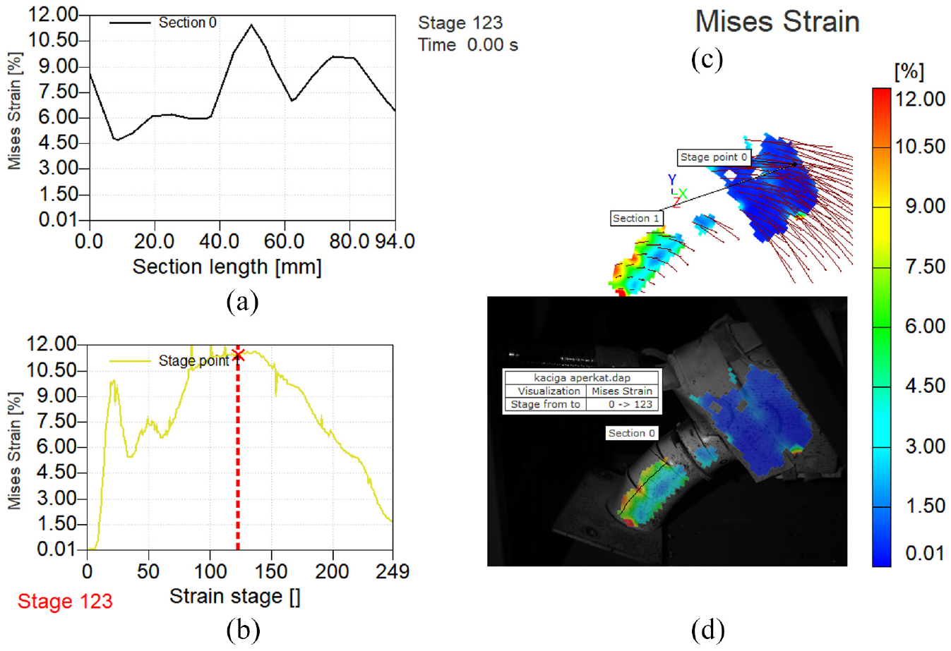
Mises strains for ura-tzuki (uppercut) punch: (a) section length, (b) strain stage, (c) deformation field, and (d) deformation field overlapped with the measuring object.

Neck displacement field with displacement vectors: (a) section length, (b) strain stage, (c) deformation field, and (d) deformation field overlapped with the measuring object.
The diagram in Figure 11(a) shows the distribution of deformations along the given length of the section on the neck at the time when the largest deformations were evidenced on the Mises Strain – Strain stage diagram (Figure 11(b)). The moment marked as stage 123, in Figure 11(b), represents the 123rd image, meaning 0.123 s from the start of the punch, that is, 0.123 s of recording, when the head model is loaded with bending in neck area. Two peaks which were noticed are related to the lower part of the neck. The first deformation peak of 11.5% in section 0 (Figure 11(a)) represents the local zone of interest and is defined on the model as strain point 1 (Figure 11(b) and (d)).
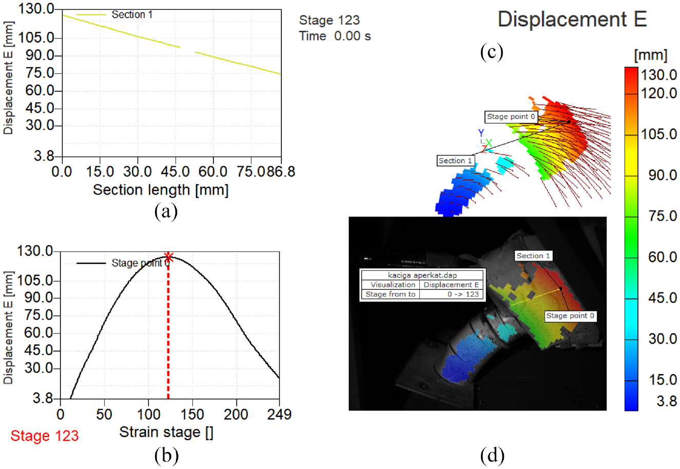
In Figure 12, at the moment marked as stage 123, which occurred as was previously stated after 0.123 s, according to a colored scale showing the movement of the neck in millimeters, movement of the neck can be noticed which is not particularly significant in terms of the risk for neck injuries. Section 0 (Figure 13(d)) corresponds to the displacement-strain stage diagram (b) whose highest peak is at a value of 10 mm which confirms the small influence of displacement on the possibility of injury in the cervical spine.
Head displacement field with displacement vectors: (a) section length; (b) strain stage; (c) deformation field; (d) deformation field overlapped with the measuring object.
The largest displacement was evidenced at point 0 (stage point 0) on section 1, which corresponds to the moment of maximum neck extension due to the imparted force after 0.123 s (Figure 13(b)). The displacement value at the moment of maximum neck extension corresponds to the highest peak on the displacement-strain stage diagram, which is at value of 126 mm.
For the mawashi-tsuki punch to the cheek due to two types of head movements after the punch, two peaks were evidenced (Figure 14(a)). The first peak which corresponds to the values of von Mises deformations of 18.5% is related to the appearance of vertebral shear which occurred in the first moment after the imparting of force to the model. The second peak on the same diagram corresponds to stage 0 in section 0 (Figure 14(d)) and it corresponds to the value of von Mises strains of 20% (Figure 14(b)). This peak is related to the moment of 0.132 s after the imparting of force to the model. Deformations that appear at the position of the head and neck in stage 132 are a consequence of the extension of the neck due to the movement of the head to the side.
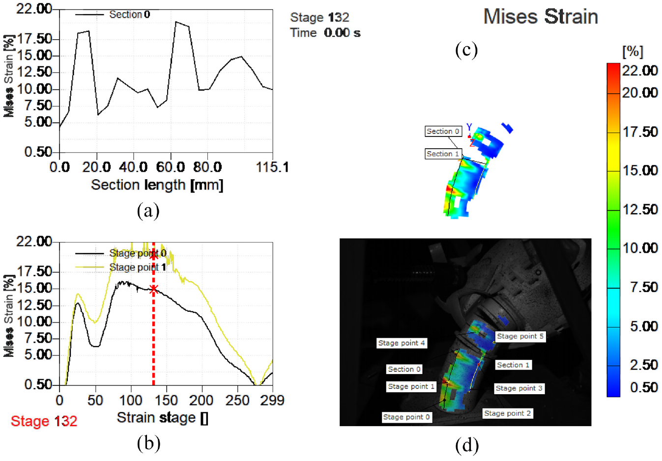
Mises strains for mawashi-tsuki (croche) punch to the cheek: (a) section length, (b) strain stage, (c) deformation field, and (d) deformation field overlapped with the measuring object.
Values which are obtained at 0.144 s after the imparting of force laterally in the area of the chin, indicate the appearance of two types of forces affecting the area of the cervical vertebrae (Figure 15). On the Mises strain-section length diagram (Figure 15(a)), the peaks in section 1 were recorded, which correspond to the values of stage point 2 and stage point 3, meaning 11% and 16%, respectively, on the Mises strain-strain stage diagram (Figure 15(b)). The appearance of the first peak is due to the deformations caused on the neck because of the rotation of the head, where the value of 11% indicates the possibility of increasing the risk of injuries to the cervical spine. The appearance of the extension of the cervical vertebrae after imaging is accompanied by the deformation recorded in the diagram of the Mises strain-strain stage at point 3 (stage point 3), whose value is 16% (Figure 15(b)).

Mises strains for mawashi-tsuki punch to the chin: (a) section length, (b) strain stage, (c) deformation field, and (d) deformation field overlapped with the measuring object.
The diagrams show the results for representative samples. For each punch, 5 measurements were made, and the text below the diagram shows the mean values obtained by statistical analysis in Excel.
Discussion
Experimental part of this paper refers to recording of deformation field in the cervical part of the spine, as well as the displacement field caused by the impact. Based on obtained results, observed highest values of Misses deformations are due to the action of shear forces on the cervical vertebrae during the ura-tsuki punch to the chin and mawashi-tsuki to the cheek, 10% and 18%, respectively. The difference of 80% in the amount of Mises deformations that occur on the neck when these two punches are performed (these punches differ only in the area of the head to which the force was applied), indicates that the risk of injuries due to shear in the cervical spine when receiving this type of punches is doubled. Regarding the maximum Misses deformations that occurred due to neck extension, recorded values for each of the punches are: 11.5% (ura-tsuki), 20% (mawashi-tsuki to the cheek), and 16% (mawashi-tsuki to the chin). Based on these data, the highest value of Mises deformations that occur due to neck extension is attributed to Mawashi-tsuki’s punch to the cheek. This value is about 74% higher than the value of Mises deformations that occur when receiving an ura-tsuki punch, and 25% higher than the value of Mises deformations that occur when receiving a mawashi-tsuki punch to the chin. The maximum Mises deformations that occur when receiving a mawashi-tsuki punches to the chin and cheek are related to Mises’s deformations caused by neck extension, and are higher than those caused by shear forces by 60% and 11%, respectively. This relation indicates the potential severity of injuries that can occur when mawashi-tsuki punch to the cheek is received. The maximum head movement in the amount of 126 mm was recorded for the ura-tsuki punch. This parameter, in addition to von Mises deformations, indicates the length of the trajectory along which head moves, whereby it acquires an acceleration that abruptly ceases at the moment of maximum neck extension. This moment is significant because it can lead to injuries in the form of concussions.
One of the technical challenges while creating the experimental settings was how to apply a constant value of impact force in order to enable repeatability of the analysis. The technical solution to this challenge is a frame-shaped construction with a weight and a limiter (Figure 5). With calculations made in the paper of Milosevic and coworkers it is obtained that impact force on the place of impact has value of 740 N. 52 In that way, it is possible to vary other parameters, such as changing the position of the examined object, in order to monitor the simulation of different punches that occur in martial arts sports. Also, this approach allows the opening of new space for future research, with the aim of analyzing the deformation of the neck when placing different helmets on the model of the head.
Previously, researchers examined statistical data on the frequency of neck and head injuries due to the sport fights, that is, martial arts, the measurement of impact forces due to a hand punches or foot kicks in the head area, as well as the measurement of forces acting on the head and neck due to impact, among the other parameters. Fernandes and Alves de Sousa concluded that different head injury criteria have been developed in previous years, regarding the impact of different injuries on the brain. Different finite element models of head were made in order to make the reconstructions of head impacts and to try to predict the threshold for head injuries. 53 However, cervical spine is, beside head that is, brain, the main location of serious injuries in combat sports. 54 Rocha Piedade et al. concluded that 10%–20% of injuries, concretely in boxing sports, are cervical spine injuries in which contusions and muscular lesions are leading.8,55 However, to our knowledge, there are no similar studies, nor results, to this one, which dealt with mechanical characterization of injuries in spine area. Certainly, there is further need for detailed studies on head and spine injuries in martial arts, different helmet options and headguards. 56
Conclusions
There is an important difference between the weight categories of fighters in martial arts, as also in the anatomical and physiological constitution of fighters (reflected in the strength of punch, speed of reaction to punch, strength of the neck muscles, etc.). Because of these parameters, it is necessary to develop model for the analysis of neck deformities and head and neck movements, which will be used for the analysis of different punches with constant force. Understanding the complete scenario in which deformations occur is the key for getting the optimized protection designs and prevention strategies in order to reduce different fracture modes.
The information obtained from the analysis of deformations that occur due to the action of impact forces when a punch to the head is performed, can be useful in developing a model that determines the degree of reduction of impact forces. This information would be also useful as it would allow testing of different materials and shapes of helmets. Developed model for determining neck deformations due to impact forces can be used to diagnose the type and mechanism of injuries, as well as to localize injuries that occur in martial arts, by comparing the limits of plastic deformations of facet joints and vertebrae on one side, and measured forces on the vertebrae on the other.
In this research, it has been shown that it is possible to detect and measure the values of deformations at the moment when the neck is loaded with shear, which can increase the risk of injuries, such as injury of the cervical spine. The highest value of deformations that occur to the neck are related to the mawashi-tsuki punch (20%). The largest measured displacements are related to the ura-tsuki punch in the value of (126 mm). Medically observed this type of results can anticipate more serious injuries from certain type of punches. These information’s, also, can further be used in researches focused on development of helmets used in sport fights which could, with its improved design, reduce values of neck deformations.
Footnotes
Handling Editor: Chenhui Liang
Declaration of conflicting interests
The author(s) declared no potential conflicts of interest with respect to the research, authorship, and/or publication of this article.
Funding
The author(s) disclosed receipt of the following financial support for the research, authorship, and/or publication of this article: This research was financially supported by the Ministry of Education, Science and Technological Development of the Republic of Serbia (Contract No. 451-03-68/2022-14/200105). This research was supported by BMA Trading Company, with help in preparation of samples and experimental setup.