
Abstract
Effects of the particle diameter and particle injection position on the gas–solid two-phase flow have important implications in the tangential inlet cyclone separator. The Navier–Stokes equation coupled with the Reynolds stress model in Euler coordinate system is adopted to describe the gas flow and the discrete phase model in Lagrange coordinate system is used to calculate the particle trajectories. Results show that the separation efficiency varies with the injection position at the inlet cross-section. It is found that the separation efficiency is increased with the increase of the particle diameter. However, when the particle diameter exceeds a critical size, the particles will deposit on the wall of the conical chamber, which leads to lower separation efficiency. The present simulation indicates that the critical size is 24
Introduction
Cyclone separators are preferably utilized in separator equipment and industrial applications with the advantages of simple structure, low cost of operation, strong adaptability, and so on. However, the flow process in cyclone separators is very complicated and is always accompanied by short-circuiting flow, vortex, and mixing, which makes the study of cyclone separators difficult.
Many studies have been performed on the influences of various parameters on the separation efficiency in cyclone separators, such as turbulent fluctuation, working conditions, concentration of particles, and particle characteristics. Li et al. 1 indicated that the separation efficiency decreases with the increase of turbulence intensity and increases with the decrease of the thickness of the boundary layer. Kim and Lee 2 reported a set of experimental data for the particle collection characteristics of small cyclone separators. They indicated that the cut-off size of particles does not change noticeably with the variation in the cyclone body size. While, at the low flow rate, the cyclone body size can cause the particle collection characteristics to become less stiff. In the simulation of cyclone separators, the particle size, density, and inlet velocity must be taken into account. Chu et al. 3 simulated the medium-coal flow in a dense medium cyclone (DMC) with the use of different models, such as CFD-LPT, CFD-DEM, the one-way coupling, CFD-DEM two-way coupling with parcel particles concept, and CFD-DEM two-way coupling models. They discuss the CFD-DEM one-way coupling model and consider particle–particle interaction on the base of CFD-LPT model and ignores the reaction of particles on fluid. Sakura and Andrew 4 showed the particle collection efficiency will increase with the increasing of solid loading rate and inlet velocity using experimental and theoretical approaches. Wu and Shi 5 used a single particle kinetic model to simulate the trajectories of particles in cyclone separators. The result shows that the part of smaller particles entering into cyclones from the top of cross-section of inlet is probably able to form an upper dust ring. Chuah et al. 6 carried out a numerical investigation on the cyclone separator with smaller cone diameter which resulted in a slightly higher collection efficiency compared with cyclones with a bigger cone tip diameter. Wang et al. 7 presented a numerical study of the gas–powder flow in a typical Lapple cyclone. They found that a particle with size exceeding a critical diameter, which was condition-dependant, would stagnate on the wall of the cyclone cone.
In this paper, numerical study of cyclone separators has been performed to investigate the detailed flow information about particle trajectories by altering the particle diameter and injection position of particles. In order to verify the tendency of the deposit phenomenon with particle size, the relationship of the unseparated particles numbers versus particle diameter is obtained with same inlet area for four different types of cyclone separators.
Numerical method
In this study, the governing equations are based on the Reynolds-averaged Navier–Stokes (RANS) equations. The Reynolds stresses are solved by the Reynolds Stress Model (RSM) which can describe the essentially anisotropic turbulence. In addition, the discrete phase model (DPM) is employed to simulate the trajectories of particles.
Governing equations
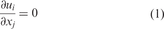
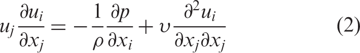
Assumed to be incompressible and steady, the continuity and momentum equations of gas flow can be written as
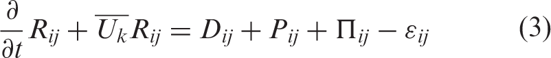
The RSM is used to close equations (1) and (2) to solve a transport equation for each component of Reynolds stresses,
8
which is given as
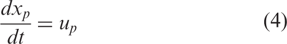
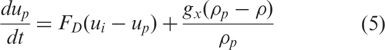
When the volume fraction is less than 10%, Lagrange DPM is adequate to predict the particle trajectories. The particle motion equation in the two-phase flow, which only calculates the gravity and gas drag forces on the particle (expressed along the coordinate axis in the X direction), is expressed as
9
Geometric model and boundary conditions
The Stairmand cyclone model is one of the highest efficiency designs mentioned in Stairmand.
10
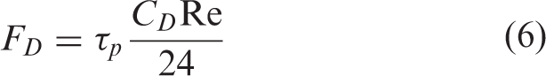
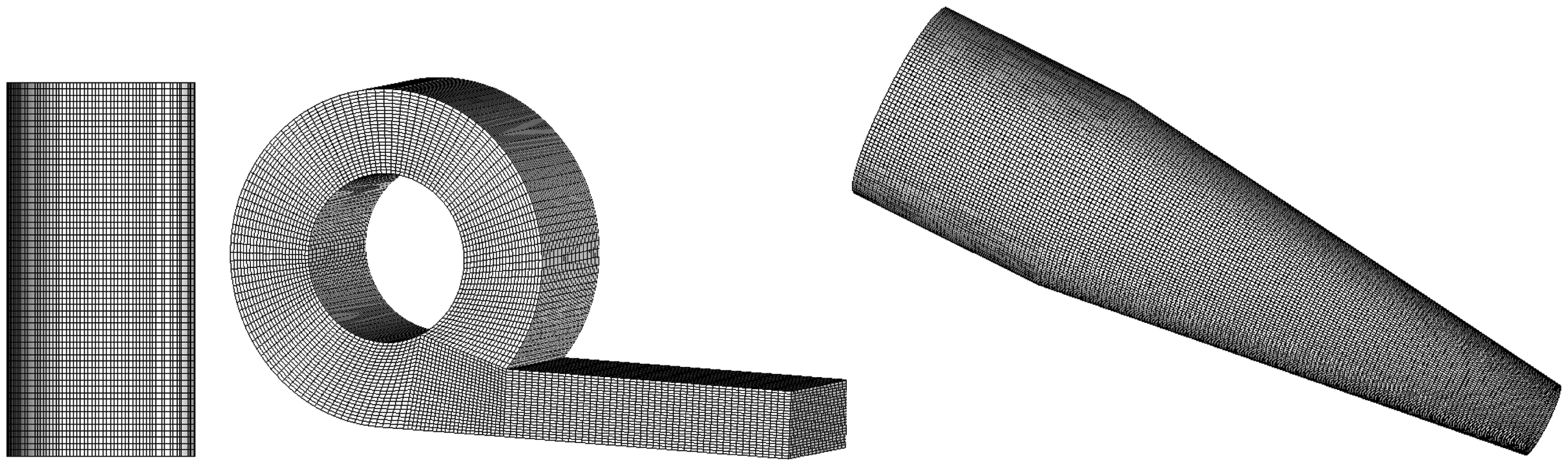
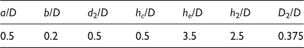
Figure 1 shows the geometric diagram of the model and the parameters are listed in Table 1. To enhance the final grid quality, the whole computational domain is divided into three blocks as shown in Figure 2. Each domain is discrete independently, and the cell number is about 1.4 million.
Schematic of cyclone separator. Computational domain of cyclone separator. Dimension of the cyclone separator (D = 190 mm).
The boundary conditions are as follows.
Boundary condition for gas phase flow
The velocity inlet boundary condition is applied at the cyclone inlet, and the velocity equals to 7.5 m/s. The outflow boundary condition is used at the cyclone gas outlet, meaning the normal gradient of variables on the cross-section is equal to zero. For the dust outlet and the other wall, the non-slip condition is used.
Boundary condition for gas–solid two-phase flow
In the gas–solid two-phase flow, there are 1400 particles injected from the inlet surface with a velocity equalling the gas phase, and the density of homogeneous spherical particle is 980 kg/m3. The simulation adopts one-way coupling calculation, meaning the gas phase flow is calculated first, and then the trajectories of particles from the initial injection position can be shown directly. Therefore, the gas outlet and dust outlet are defined as “escape” and “trap” for two-phase flow on the basis of the gas phase flow simulation, respectively, while other boundaries are defined as “reflect”.
Formulation of particle deposit phenomenon
Some researches found that the separation efficiency increases with the increase of particle diameter.
11
But, when the force on the particles is balanced along the axial direction, the particles will keep spinning and deposit on the conical chamber wall. As shown in Figure 3, the force acting on the particle in the conical chamber is analyzed. The relationship of various forces acting on the particles in the conical chamber is as follows
Force analysis of the particle in the conical chamber.
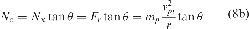
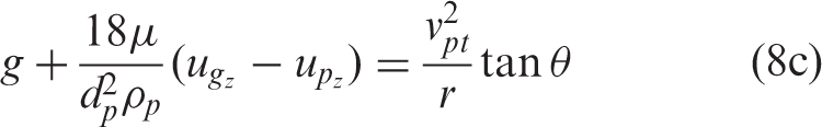
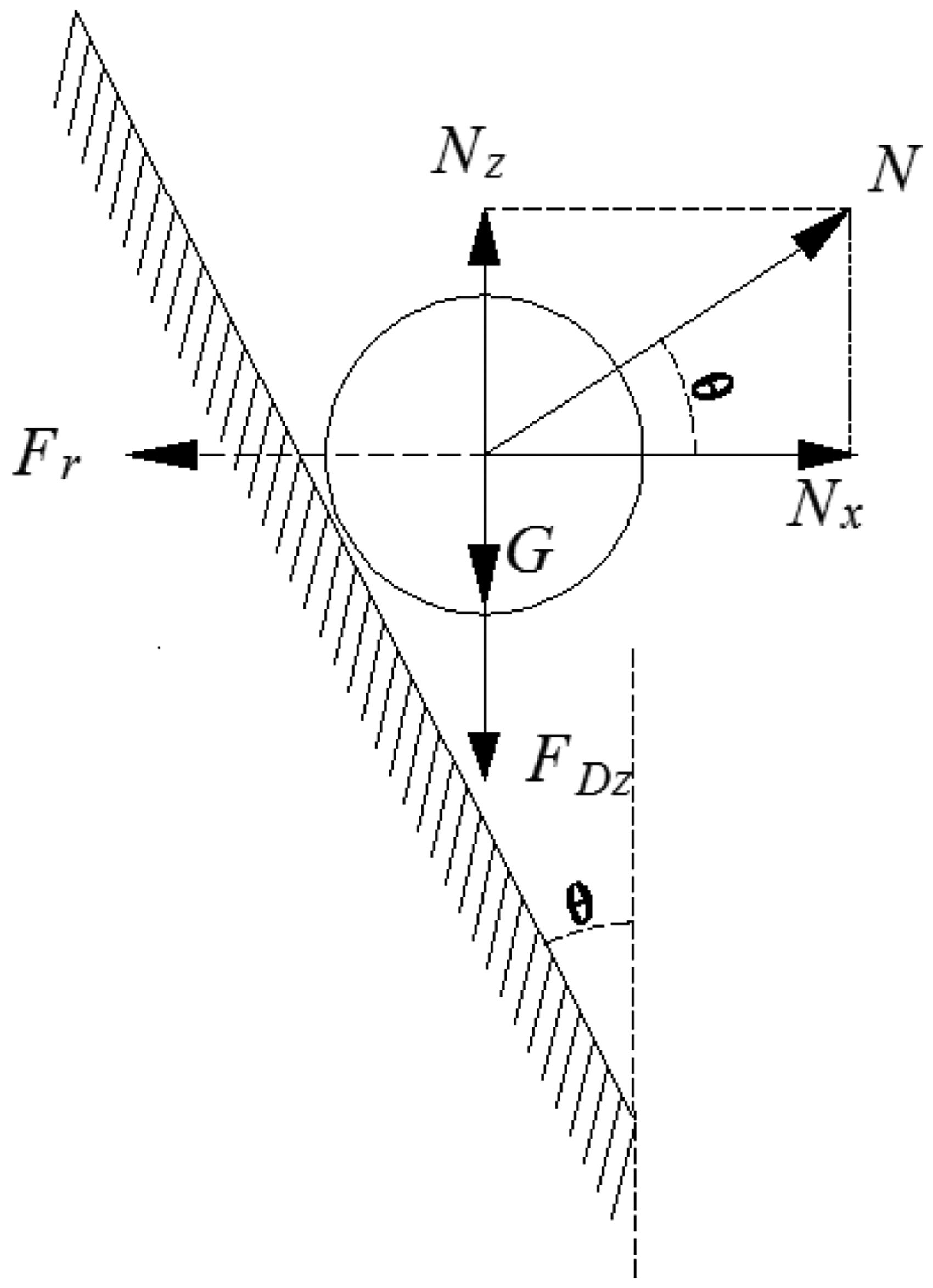
It is noted that the centrifugal force Fr will increase when the particle diameter dp increases. Also, the radial component Nx of the supporting force N increases with the increases of centrifugal force, so the axial component Nz increase. Meanwhile, the force on the particles will be balanced along the longitudinal direction.
Results and discussions
Mesh independency study
In order to validate the numerical model, three sets of grids are tested which contain 0.7 million, 1.4 million, and 2.9 million cells, respectively. Figure 4 shows the distribution of pressure drop versus the number of cells. The result shows that the difference is less than 5% for the pressure drop. Thus, the numerical model is validated and the computed result is independent of the mesh size. Meanwhile, the subsequent analysis is based on the 1.4 million cells case.
The study of grid independence.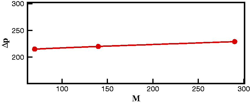
Simulation of particle trajectory
Influence of the initial injection position on the particle trajectory
Following the method of Hu et al.
12
and the control variable method, the cross-section of the inlet is divided into four regions, as presented in Figure 5. Figure 6 shows the particle trajectories with the diameter of Partition of the inlet section. Trajectories of particles with the diameter of 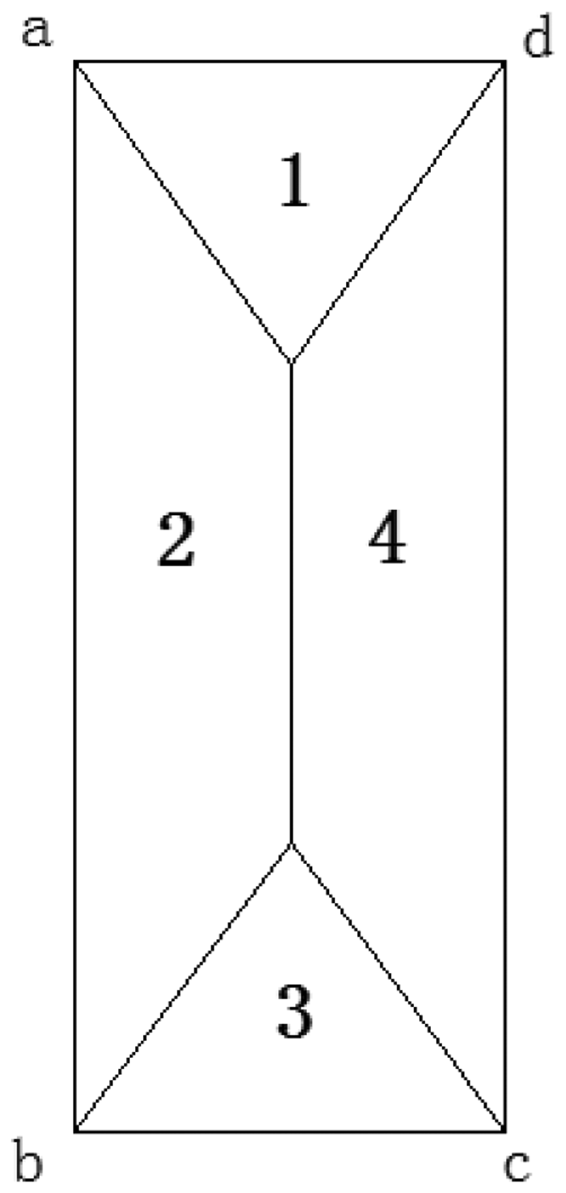
In order to fully study the effect of the initial injection position on the particle trajectory, the residence time of the particles with the diameter of Residence time of the particles with the diameter of 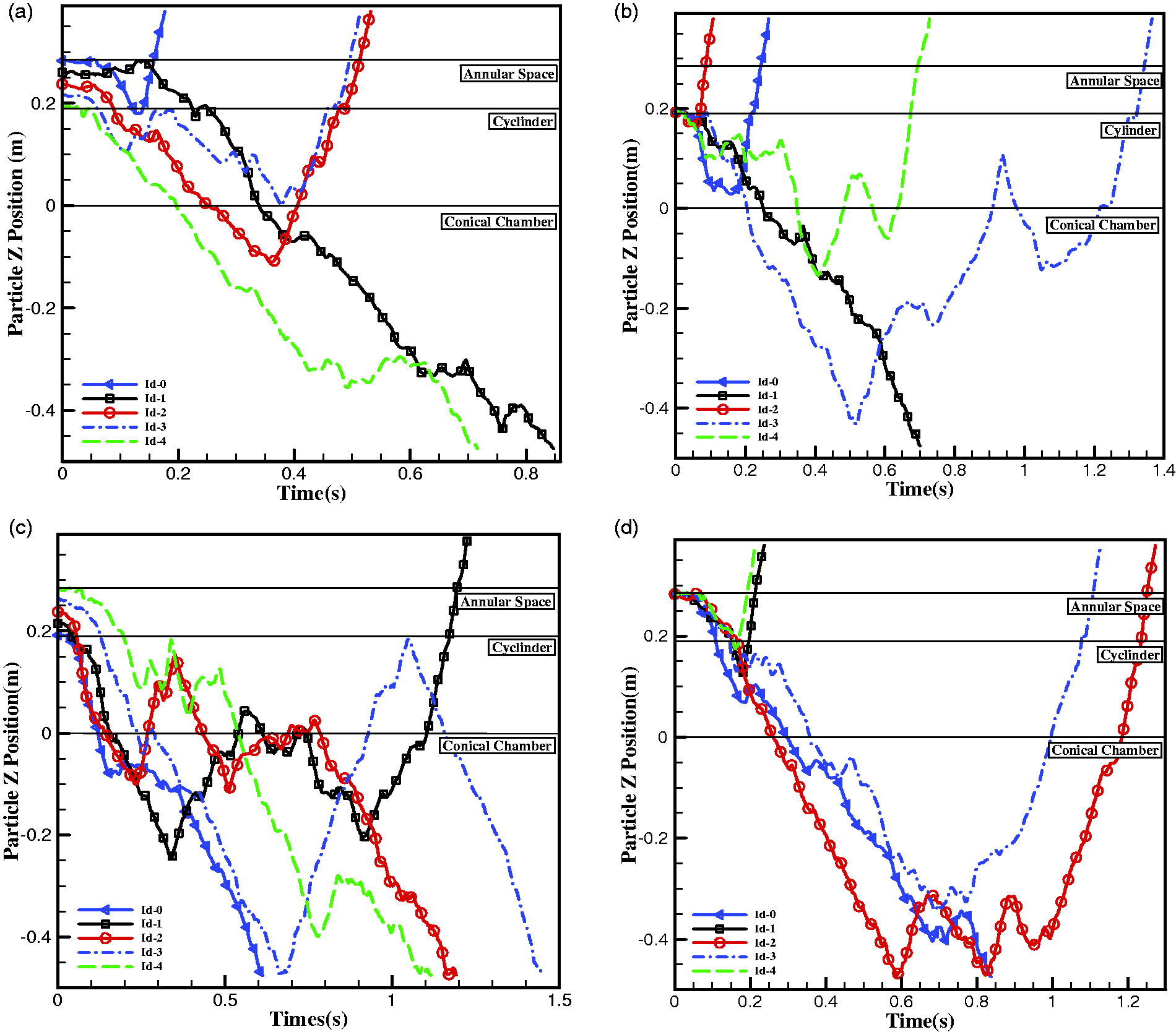
Influence of the particle diameter on the particle trajectory
Figure 8 presents the trajectories of particles with the diameter of Trajectories of particles with the diameter of 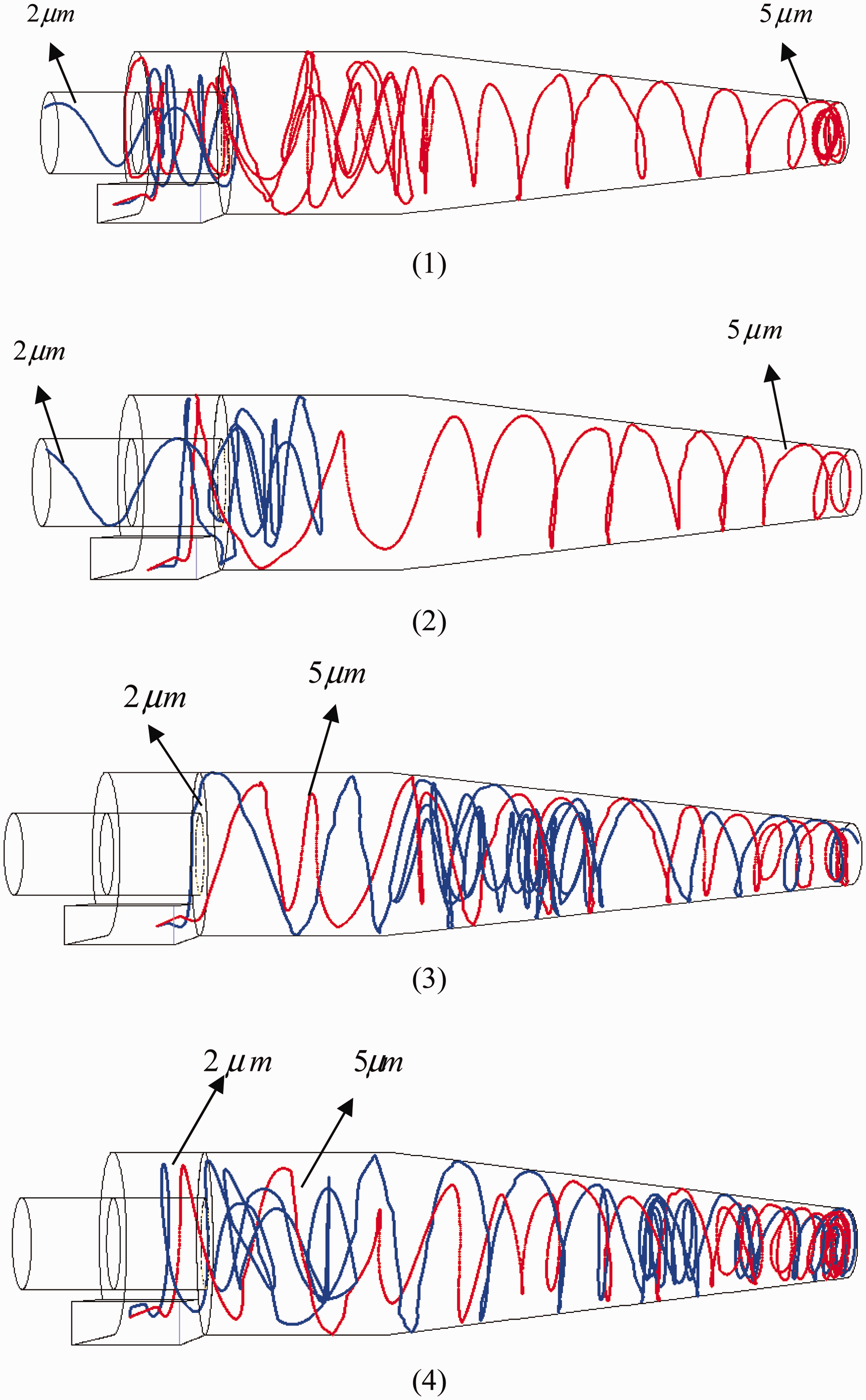
The mechanism of the effect of the turbulent dispersion on the particle trajectory can be explained with the Stokes number (Stk)
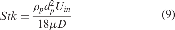
The Stk is defined as the ratio between the particle relaxation time
The Stokes number Stk describes the following behaviors of the suspended particles with fluid, i.e. the smaller the Stk, the stronger the following behaviors of particles and vice versa. According to equation (9), as the particle diameter dp decreases, the particle Stk will decrease. Thus, the following behaviors will increase and the effect of the turbulent dispersion on the particle trajectory will become larger.
Particle deposit phenomenon
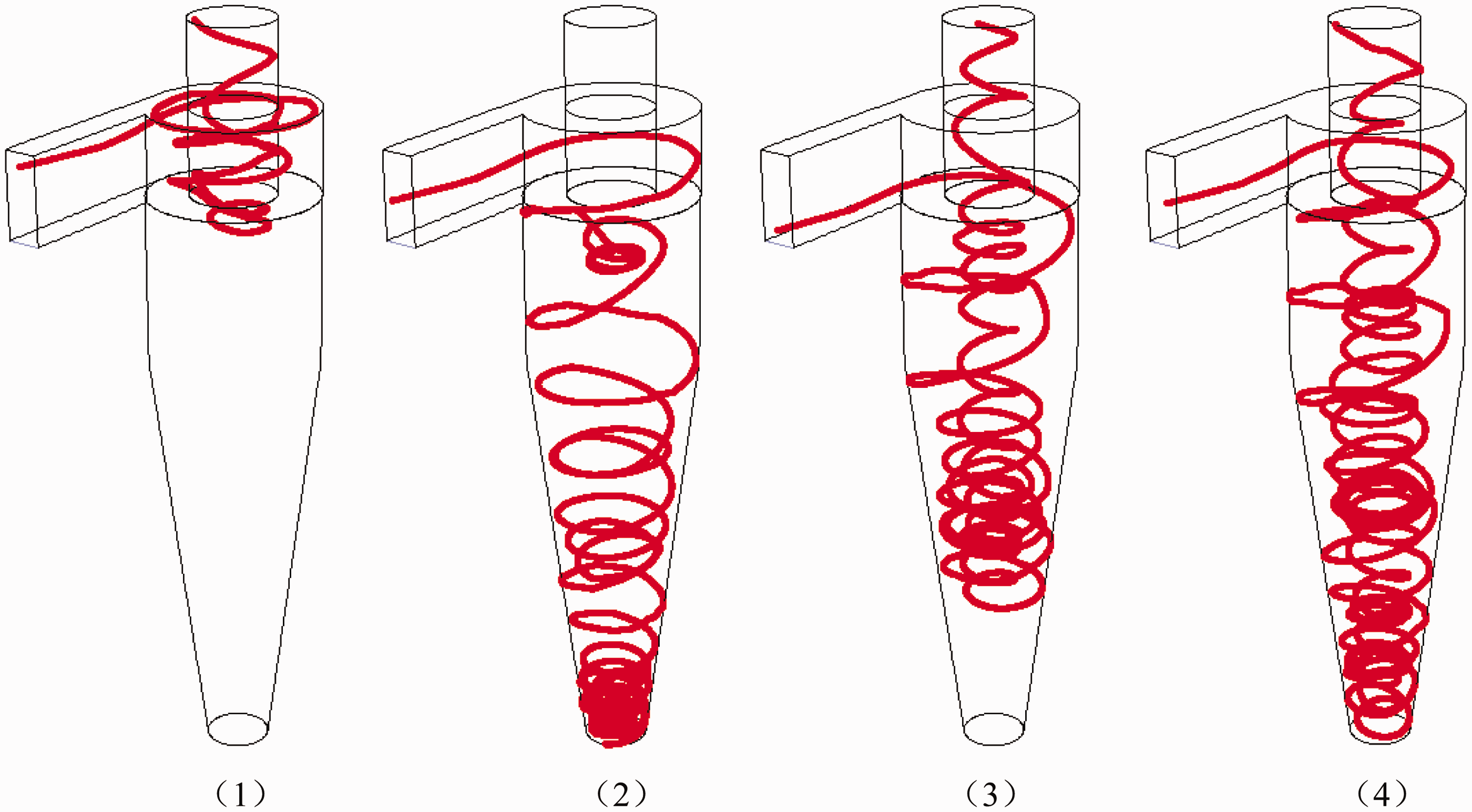
In order to reveal the mechanism of particle deposit phenomenon, the trajectories of particle with different diameters are studied, as is shown in Figure 9. From the figure, we can see that the particles keep spinning and depositing on the wall. Then, combining Figure 9 and the analysis of equation (8), it can be seen that the bigger the diameter of the particle, the larger the gyration radius r. As mentioned above, when the forces exerted on the particles reach an equilibrium state and the r is larger than the diameter of the dust outlet, the particle deposit phenomenon will happen.
Trajectory of particles with the diameter of: (a) 60 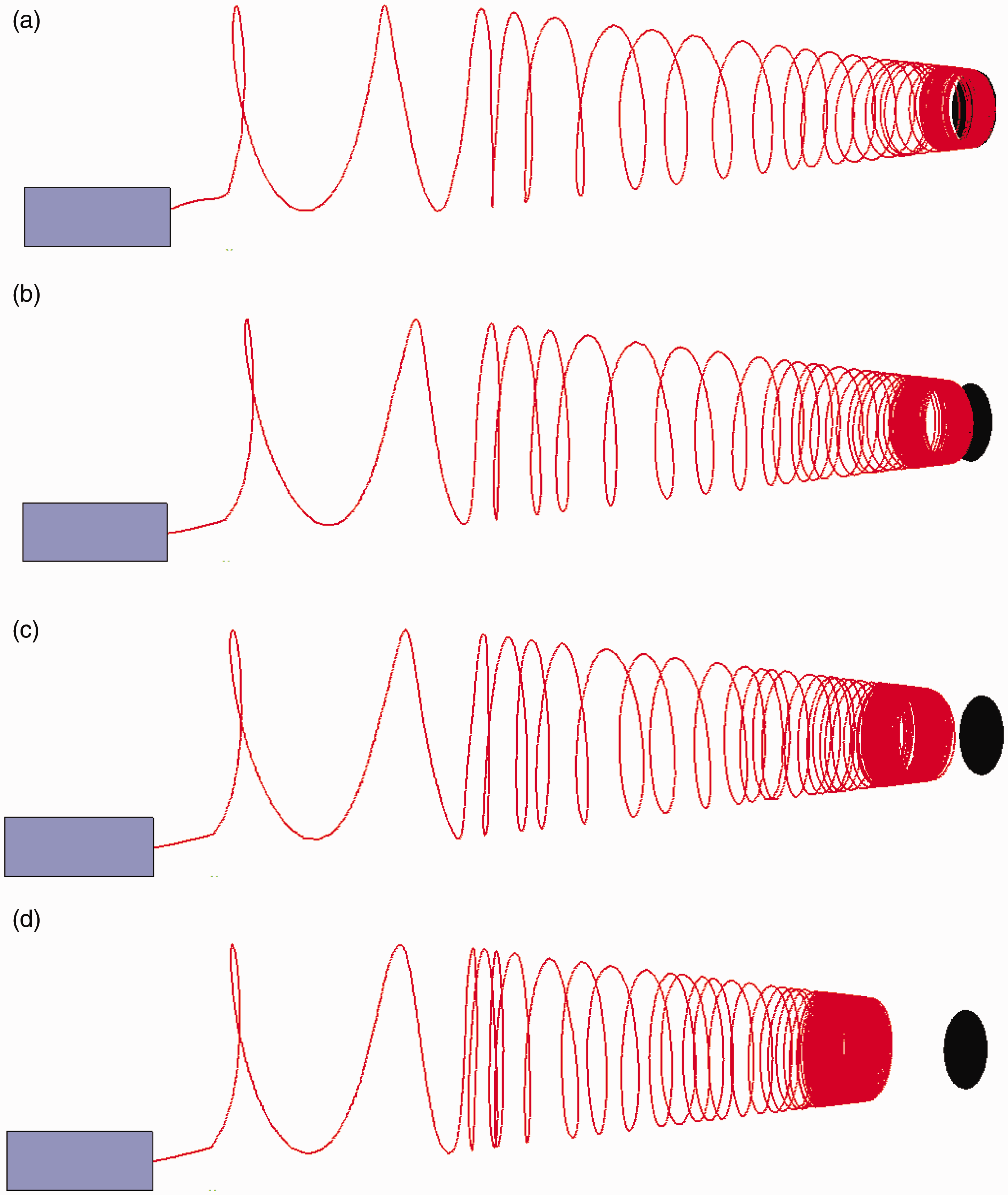
Figure 10 shows that the percentage of the number of unseparated particles versus particle diameter for four different cyclone separator models. For the present model, when the diameter exceeds 24 The percentage of the number of the unseparated particles versus particle diameter (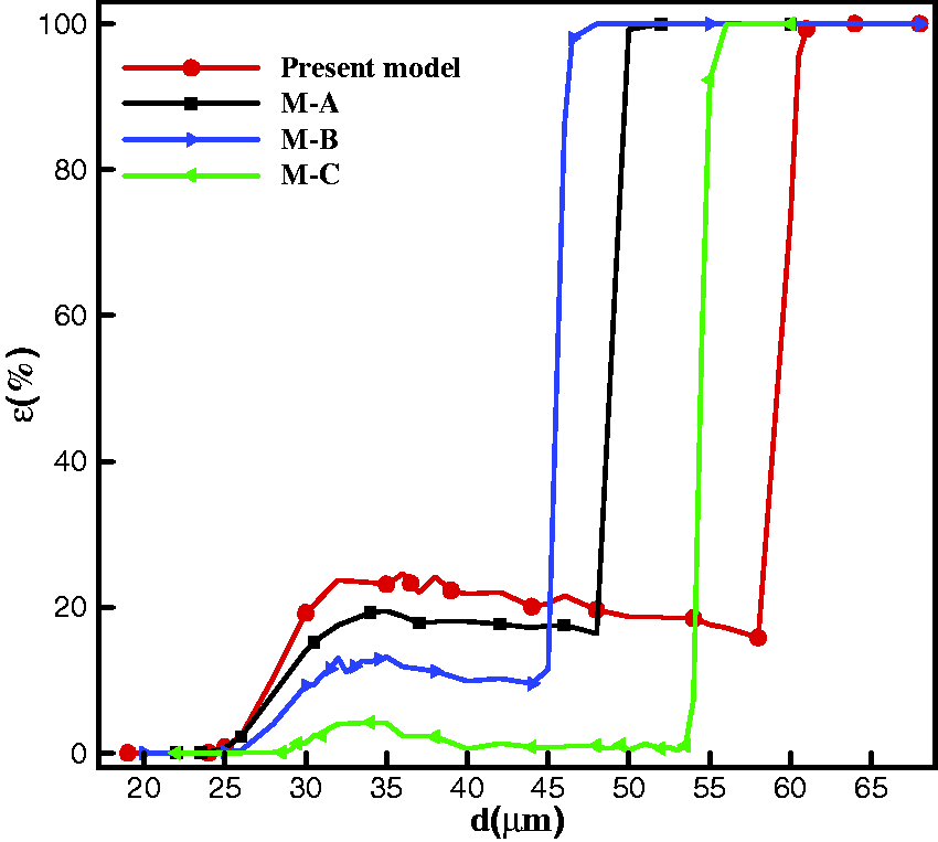
As is well known, the distribution of the separation efficiency versus the particle diameter is “S”-type.
14
The behavior of the number of the unseparated particles versus particle diameter, shown in Figure 10, is similar to the S-type separation efficiency. It is observed that cyclone separators can only collect particles with a certain range of size. The range of particle size collected is 0–62
Geometrical dimensions of the four cyclone separator models.
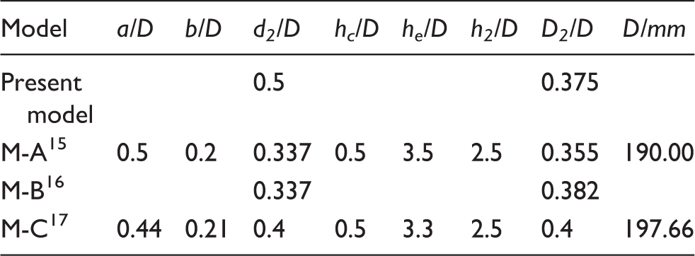
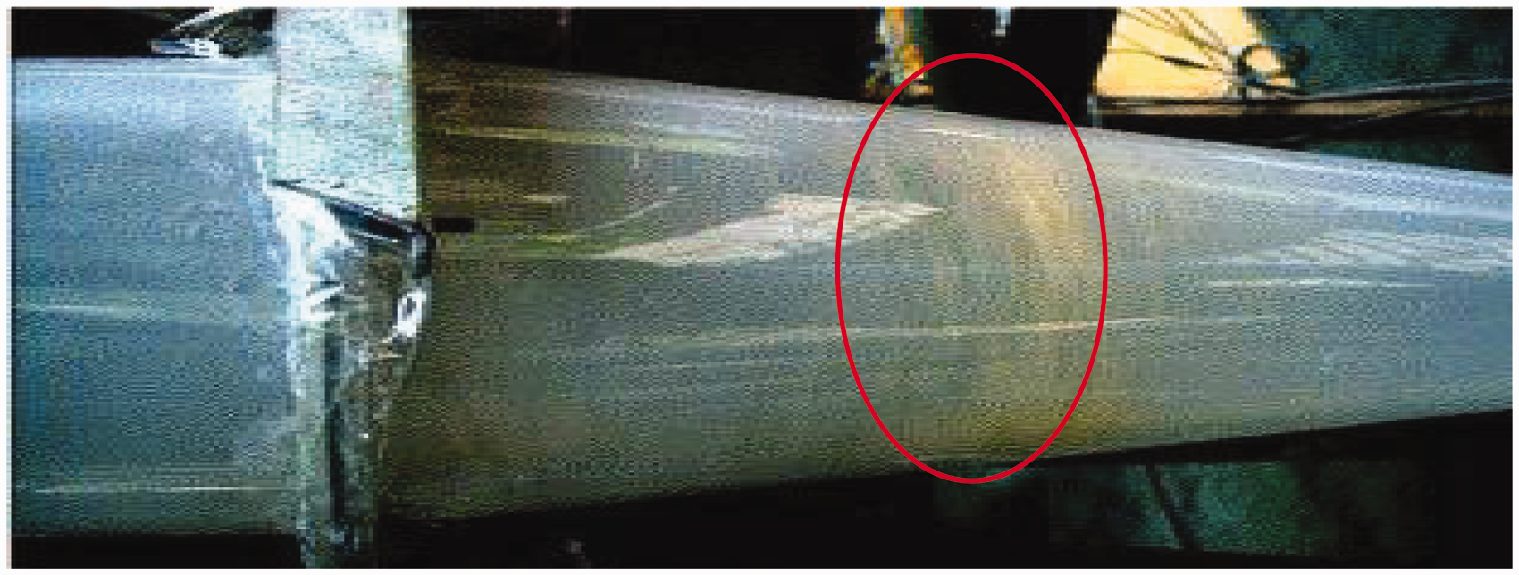
Figure 11 shows the trajectory of particles taken from the experiment.
7
From Figure 11, it can be seen that the particles deposit on the wall of the conical chamber and finally they are difficult to be collected by dust outlet. This experimental phenomenon confirms the simulation results for large size particles shown in Figures 9 and 10.
Trajectory of particles of experimental results.
7
Conclusions
This paper presents a numerical study of the gas–solid two-phase flow to analyze the effects of initial injection position and particle diameter on the separation performance. The conclusions can be drawn as follows:
The separation efficiency varies with the injection position at the inlet cross-section. For the same size particle with different initial injection position, the residence time is different. That is, the longer the residence time, the higher the possibility of the particle–wall collision. Hence, the higher separation efficiency can be produced. The separation efficiency of cyclone separator is very sensitive to the changing of particle diameter. The increasing diameter of particle leads to increasing separation efficiency within a certain range. Particle deposit phenomenon on the wall exists in tangential inlet cyclone separators. When the particle diameter exceeds a critical size, the particles will deposit on the wall of the conical chamber. This phenomenon reduces the separation efficiency and increases the wall wear rate of the cyclone separators which reduces the life of the cyclone separator. For the separator studied in this paper, the critical size is 24
Footnotes
Declaration of conflicting interests
The author(s) declared no potential conflicts of interest with respect to the research, authorship, and/or publication of this article.
Funding
The author(s) disclosed receipt of the following financial support for the research, authorship, and/or publication of this article: This work is supported by the National Natural Science Foundation of China (51579224) and Zhejiang Province Science and Technology Innovation Team Project (2013TD18).