
Abstract
A micro-tensile fatigue test of 42CrMo alloy steel was carried out. The result shows that the crack initiation and propagation of the material could be characterized with randomness and localization. There existed two sorts of short fatigue crack propagation behaviors for the tested material, that is, self-propagation and joint propagation with other short cracks. A short fatigue crack growth rate function was built considering the propagation characteristics. Moreover, a simulation model of short fatigue crack evolution was built. Total three samples were tested and simulated. The experimental result was in good consistent with that from simulation, both showing that the crack growth rate accelerated first and then decelerated during propagation.
Introduction
Regardless of service conditions of engineering parts, fatigue damage process generally means that defect nucleates in an undamaged region and then propagates steadily until a sudden break occurs. A few previous studies have shown that there existed transient acceleration or deceleration characteristics related to the subcritical growth of short fatigue cracks.1–3 The retardation or stagnation phenomenon of short fatigue crack during propagation indicates that there is a threshold of short fatigue crack growing, 4 which is different from that of long fatigue crack. This threshold is supposed to be independent of crack growth rate obtained by Linear Elastic Fracture Mechanics (LEFM) and crack size. 5 Generally, the behaviors of different short cracks vary greatly, so it is very limited to study the behavior of a single short crack only. In the process of short crack growing, fatigue damage depended largely on the interaction of many cracks. 6 The differences of microstructure growth conditions at the crack tip are considered to be the root reason of the randomness of damage nucleation and short crack initiation. The stochastic analysis method for fatigue crack propagation mainly includes mathematical model7–9 and physical simulation method.10–13
At present, the micro-mechanism of fatigue damage has not been fully and systematically understood, and the rules of short fatigue cracks growing and population evolution need to be further clarified. 14 Therefore, in the current study, a micro-fatigue short crack test was carried out, the group behavior of fatigue short cracks was analyzed, and a simulation model of fatigue short crack evolution was built and verified.
Experimental details
Fatigue failure usually originates on the surface of samples. The micro-fatigue testing device can observe the initiation and propagation of surface cracks in real time at metallographic level.15,16 The chosen material of the micro fatigue test is 42CrMo. The measured chemical composition of the material in wt.% includes: 0.42 C, 0.31 Si, 0.57 Mn, 0.20 Mo, 0.95 Cr, 0.03 P, 0.016 S, 0.105 Cu. After annealing, the metallographic structure of the material is ferrite and pearlite, and the average grain diameter is

Original morphology of annealed 42CrMo.
The sample profile and dimensions are shown in Figure 2. For easy observation under microscope, two small notches with dimension of 0.5 mm×0.2 mm were pre-cut on both sides of sample before test to induce crack initiation. The samples were finely ground and polished to facilitate online monitor. After the test was completed, the sample surface was slightly corroded by 3% nitric acid alcohol solution for metallographic morphology observation.

Sample profile and dimensions.
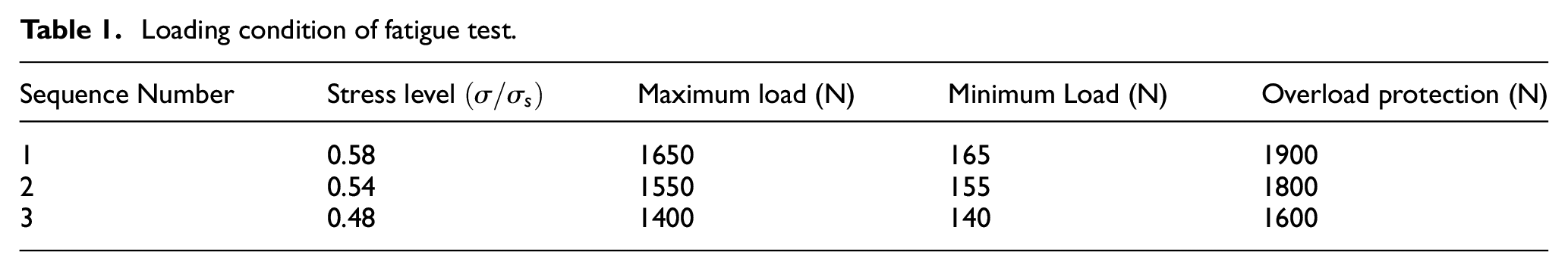
The fatigue test device used in the experiment was similar to that in Yang et al]. 16 The prepared samples was fixed on the fatigue test device. A microscope was fixed above the sample for real-time observation. The loading frequency was kept at 1 Hz with a stress ratio of 0.1. The test was carried out at room temperature in air. Total three samples were tested. The loading conditions are listed in Table 1.
Loading condition of fatigue test.
During the test, the testing device came to a halt after running 300–1000 times loading cycles. The test process data was recorded by a camera installed above the microscope. A computer was connected to the camera to perform real-time observation and data recording. During each halt, the metallographic structures and fatigue cracks of the samples were observed under a microscope. Meanwhile, some interesting images were saved for further analysis.
Characteristics of short fatigue crack initiation and propagation
The nucleation of fatigue short cracks is often due to the presence of slip bands, grain boundaries and inclusions where short cracks are initiated due to stress concentration. After undergoing an initial several thousand cycles, at about the life fraction
According to the observation and analysis of crack localization characteristics in micro-fatigue tests, the evolution of short fatigue cracks was usually characterized by localization. 6 During crack initiation and propagation process, denser short fatigue cracks appeared in a few regions, while there was little damage occurred in other regions (Figure 3). According to the theory of damage mechanism, this uneven damage was caused by differences in local structures of the material. As the strength of pearlite is higher than that of ferrite (about 560 MPa for ferrite and 820 MPa for pearlite), the crack mainly propagated along the grain boundary or through ferrite.17,18 Previous study also reported that cracks were found to propagate inside ferrite, pearlite and their boundaries.19–21 Within experimental scope, pearlite was the least sensitive to crack propagation, followed by ferrite, and grain boundaries were the worst, therefore crack was most likely to propagate grain boundaries.

Localized nature of initiation growth of Fatigue Short Cracks.
On one hand, the grains and grain boundaries in local region of metallic materials might act as natural physical barriers to crack growth. 22 On the other hand, short cracks might also be caused by inconsistent plastic deformation, which were easy to converge with local dominant cracks, and thus promoting rapid crack growing, 23 that is, local micro-structure might serve to promote or hinder crack growing instead.
Observation of the short fatigue cracks on the sample surface reveals that the crack behavior had the following characteristics:
The initiation of short fatigue cracks was random. Short cracks originated in the stationary slip bands inside ferrite grains and ferrite-pearlite grain boundaries, but the short cracks at these locations tended to become non-propagating cracks, while short cracks at the grain boundaries or at the material defects were more likely to become propagating cracks. It was difficult to control the micro-local plastic deformation during the crystallization process of material preparation, and the micro-roughness of surface could not be eliminated by subsequent processing. Therefore, the initiation conditions of short cracks were random.
The initiation of short fatigue cracks was characterized by localization. There were a large number of cracks in the short crack stage. However, the group cracks of the test material were not uniformly distributed on the surface of the material, but concentrated in some ferrite regions in the form of resident slip bands.
The propagation of short fatigue cracks was localized. Certain localities of the test material might be favorable for the initiation of cracks and the early initiation of short cracks, but might not be conducive to crack propagation. Others, on the other hand, might be detrimental to crack initiation, but the short crack propagated faster in this region. Therefore, sometimes short cracks in unfavorable localities might propagate faster in the later stage and became locally dominant cracks beyond the initial cracks.
Short fatigue cracks presented two modes of propagation: self-propagation and convergence with other short cracks. In general, the crack growth rate had the characteristics of acceleration first and then deceleration. The crack propagation tended to slow down when the crack tip met grain boundary or pearlite, and the direction of propagation changed accordingly. When the crack tip encountered a randomly distributed short crack concentration area, the confluence of the cracks accelerated crack growing and the direction of propagation turned after the confluence. Therefore, from the microscopic point of view, the rate and direction of crack growth changed significantly after being hindered by grain boundaries or being converged with other short cracks.
The above evolution characteristics of short fatigue crack illustrated the particularity and complexity of short crack behavior. Although there have been several micro-damage mechanisms to explain the transient anomaly of short crack initiation and propagation, how to visualize the random physical damage process and non-linear behavior of short crack at a micro level still needs to be further investigated.
Fatigue short crack evolution model
Local dominant crack characteristics
The study of the evolution of short cracks revealed the relationship between the physical process of micro-damage and the mechanical properties of the damaged material. 24 The parameter of crack number density was often used to describe fatigue short crack damage, which reflected the contribution of crack number to fatigue damage in multi-crack specimens. In the existed studies, the initial evolution of short fatigue crack population was thought to be sparse and have little interaction between cracks. Literature 25 gave an ideal short crack model to analyze the early stage of short crack evolution by combining the number and length of cracks. In fact, although the short fatigue cracks of smooth plate specimens had group behavior characteristics, the fatigue damage did not develop uniformly inside material. According to the results of micro-fatigue test, there was almost no damage being found in some areas where were insusceptible to crack, while there were dense short fatigue cracks in areas where were prone to crack. Therefore, the evolution of short cracks was characterized by dominant cracks with obvious local evolution.
However, localized fatigue damage did not develop linearly. The localized damage process could be divided into two stages: Localized ideal short crack stage and locally dominant crack control stage. First, in the initiation stage of a short fatigue crack, some regions, such as grain boundary defects and grains at slip lines, were considered as susceptible sites of crack initiation. At this time, there was almost no interaction between cracks. The nucleation and propagation of short fatigue cracks were independent. The damage extent of short fatigue cracks could be described by an ideal short crack system evolution model. With the propagation of fatigue process, the short fatigue crack initiation stage entered the locally dominant crack control stage. At this stage, the interaction between cracks in the areas far away from the damage concentration area was weak, and the fatigue damage caused by short cracks in these areas had little or no influence on the damage process and amount. The interaction between cracks in the damage concentrated region had a strong influence on the initiation and propagation of cracks and was easy to form Dominant Local Field Short Cracks (DLFSC). DLFSC and its damage-affected zones should be key considerations when building fatigue shortcrack damage model since they could more easily evolve into “long cracks” that finally cause part failure. The two stages of localized damage process had different characteristics in terms of crack growth rate. The boundary of the two stages could be related to crack length. When crack length was less than a threshold value
Unlike long cracks, the propagation of DLFSC was more influenced by the length, amount and microstructure of short fatigue cracks around it. Since crack initiation at the initial stage of damage was controlled by many factors, the location of crack initiation was random, and the area where the damage was concentrated was sparsely distributed, so there were many DLFSCs. The stress concentration in the tip region of DLFSC resulted in grain boundary cracking and intra-grain slip. As a result, more short cracks tended to form in crack tip regions. DLFSC was further propagated by combining these short cracks. The amount, length and orientation of initiation cracks in the crack tip region (including grain boundary and intra-grain) were random due to the differences in local microstructure of materials, and the growth behavior of DLFSC was also random.
Fatigue short crack propagation model
Hypotheses
Based on the analysis of the micro-mechanism of random propagation of DLFSC, the hypotheses of locally dominant crack damage model are proposed:
In the initial stage of damage, the short crack initiation process is very short, and its effect on material damage and life can be neglected.
After the formation of local dominant crack, it becomes the main factor of material damage.
There is a concentrated area of short cracks at the local dominant crack tip, in which the characteristics of short cracks are the same as those of the ideal short crack system.
The locally dominant crack propagates through itself and its connection with the existing short crack in the tip region.
Formula analysis of fatigue short crack growth rate
Based on the above assumptions and the research results of fatigue short crack growth law, the formula of fatigue short crack growth rate is obtained:
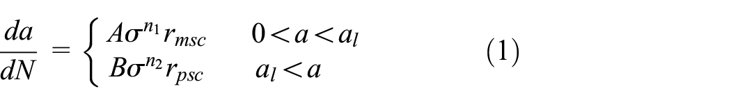
Where
Following gives a detail description of the above parameters:
Formula (1) describes the two stages during fatigue short crack growing. There existed a critical threshold for crack length (referred as to
Equation (2) reflects that the growth rate of short fatigue crack is affected by the level of loading stress. Short crack growth rate increases when the stress level is high, and decreases when the stress level is low.
The sizes
Size analysis of plastic impact zone based on local microstructure
Metal materials show varying degrees of immunity to the initiation and propagation of Fatigue Short Cracks in different localities, and the number and size of cracks in each locality reflect the extent of local damage. Generally speaking, when the cracks in the adjacent area of the DLFSC tip are too sparse, that is, the size of the plastic affected zone at the crack tip is very small, and when the cracks in the adjacent area of the DLFSC tip are too dense, the plastic affected zone at the crack tip is very large. Therefore, the density of short cracks in the local region of the short crack tip can be regarded as a certain value, and the sizes
Corresponding to the existing law of fatigue short crack growth, the dimensions
(1)

The duplication technique is used to observe short cracks. 26 When the crack length is less than the threshold, the crack growth rate is independent of crack length and only changes potentially with stress level. When the crack length exceeds, the crack growth rate is proportional to the crack size and potentially related to the stress level. However, this conclusion is obviously different from the existing understanding of the fatigue short crack growth rate, possibly due to inaccurate observation of the test process.
(2)

Where m1 and m2 are indices reflecting the influence of crack length on crack growth rate.
Considering the characteristics of fatigue short crack that crack growth decelerates first and then accelerates, when the length of short crack is less than the critical scale
Parameters for crack growth rate calculation.

(3)

Where
Local damage randomness coefficient
The formula for fatigue short crack growth rate based on local randomness is obtained by substituting equation (4) with equation (1):

Formula (5) reflects the unity of randomness and certainty of local main crack growth. It can be used to simulate the evolution of fatigue short crack and reproduce the local characteristics of non-expanding initiation crack, crack growth rate, and crack damage.
Short fatigue crack evolution simulation
Simulation method of fatigue short crack evolution
Monte Carlo simulation provides a convenient method to investigate the initiation of fatigue crack at a micro-scale. 29 Here, a simulation method was proposed based on Monte Carlo simulation. Following gives a detail description of calculation process.
Simulation of material microstructure: A hexagon grain background diagram was constructed as a two-dimensional microstructure diagram of the material. The sizes of hexagon was determined by the average grain size
A certain number of “crack initiation sites” are randomly set in the grain. Cracks randomly originate at the sites and the lengths of the cracks cannot exceed the grain size, which is considered as non-propagating short cracks. The crack initiation sites includes grain slip zones, grain boundaries, inclusions, etc. The amount of sites
The crack initiation sites are randomly set at the edge of the material. The short cracks initiated from these sites are DLFSC.
The characteristic pattern of crack determines the growing rate of crack.
When the crack tip reached grain boundary, it will continue to grow or stop growing temporarily according to the characteristic pattern. Every time a crack crosses the grain boundary, it is no longer considered the original crack, but its descendants. The new characteristic pattern of the offspring crack is inherited from its predecessor.
The different local damage randomness coefficient
It is assumed that when the distance between adjacent cracks reaches the mandatory crack connection condition,
30
the cracks converge:
When the DLFSC reaches a certain size, crack propagation enters the long crack stage, and the simulation ends.
Simulation and verification of 42CrMo microfatigue test
The hexagonal grain background map was built according to the average grain size (
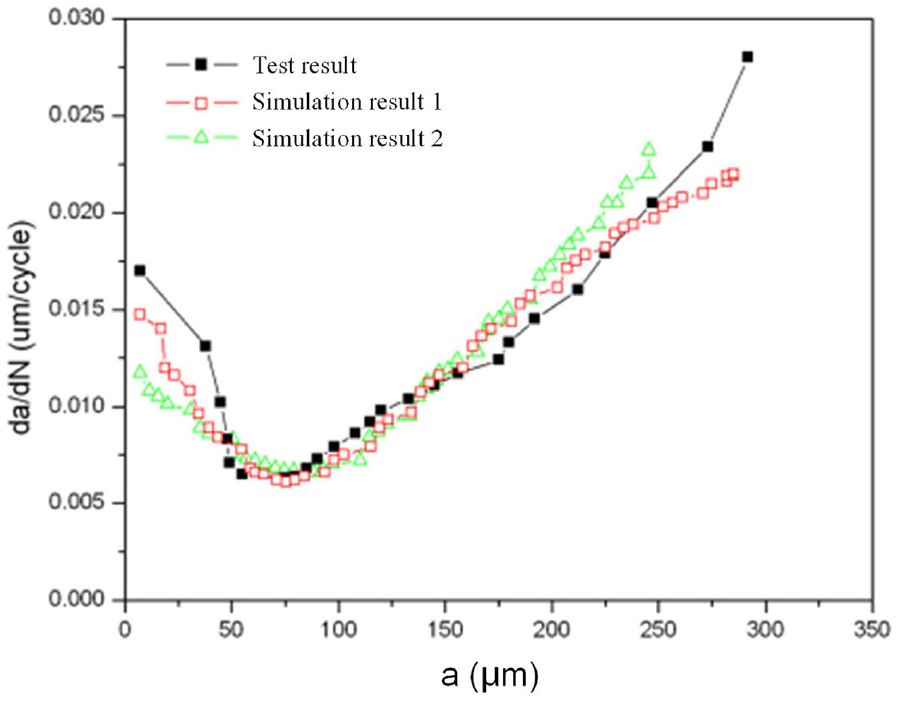
Figures 4 to 6 are the simulation results of DLFSC growth rate with crack length at loading stress levels of 1400, 1550, and 1650 N, respectively. It can be seen that the simulated

Comparison of DLFSC simulation and test results at 1650 N load propagation.
Comparison of DLFSC simulation and test results at 1400 N load propagation.

Comparison of DLFSC simulation and test results at 1550 N load propagation.
Conclusions
Based on the analysis of fatigue short crack propagation characteristics, a formula of fatigue short crack growth rate was established. The fatigue short crack growing process could be divided into two stages: micro short crack stage and physical short crack stage. Although the crack propagation had different features in the two stages, both were related to the short crack length and the dimension of plastic influence zone of crack tip.
A simulation method for fatigue short crack evolution has been designed. The simulation was based on the hypothesis the crack sources were distributed at random inside material. The method takes into account the effects of material microstructure, non-propagating cracks on the propagation behavior of DLFSC, as well as the local characteristics of crack damage. The experimental observation from the 42CrMo micro-fatigue test proved the fidelity of the simulation.
Footnotes
Handling Editor: Chenhui Liang
Declaration of conflicting interests
The author(s) declared no potential conflicts of interest with respect to the research, authorship, and/or publication of this article.
Funding
The author(s) received no financial support for the research, authorship, and/or publication of this article.