
Abstract
The valve spools of hydraulic actuator systems are usually designed into various geometries to achieve different flow characters. Because of the coupling nonlinear flow rate-pressure character and dynamic motion of the valve spool, self-excited vibration can happen in some working conditions of the system, which can lead to unexpected dynamic performance. The object of this paper is to investigate the stability of a hydraulic system with three different spool geometries, a normal sharp edge spool, a spool with chamfer, and a spool with u shape notches. Computational fluid dynamics (CFD) simulations of flow force and flow rate under different pressure difference and valve openings are proposed to obtain the pressure-flow characters of flow field inside the valves with different spool geometries. A nonlinear dynamic model of the actuator system dynamics is established basing on the CFD results of pressure control valve and the system. Numerical Bifurcation analyses are carried out to study the effect of spool geometries on the bifurcation point of the system. Simulation results suggest that the spool geometries can affect the flow characters of the valve and decrease the stable region of the parameter plane.
Introduction
Hydraulic actuator systems are utilized in many engineering application conditions to convert powerful hydraulic energy to kinetic energy. 1 The demand of the system is to control the position and velocity of the actuator piston precisely by adjust the flow and pressure in the piston chamber. 2
To obtain a fast response, large flowrate, and high accuracy hydraulic actuator system, multiple valve geometries have been proposed due to the advantages such as wide flow rate range and less axial flow force. Borghi et al. 3 presented theoretical and experimental results on the influence of shape and number of spool notches on the discharge characteristics including discharge coefficient, velocity coefficient and flow angle of a hydraulic distributor metering edge. Guillermo 4 proposed a geometric smoothing method to minimize vortical structures at the piston exit and reduce potential cavitation, noise, and vibrations, which helps to increase valve coefficient and reduce the area affected by cavitation. To clarify the effects of the groove shape on the flow characteristics, Ye et al. 5 presented CFD simulation and experimental investigation of the flow characteristics of three different notches with their corresponding typical structural grooves. The effects of groove shape on the flow area, discharge characteristics, jet flow angle, steady flow force and the throttling stiffness of the spool valve are investigated. Lisowski et al.6–8 analyzed the flow characteristics of a proportional flow control valve and improved its characteristics by means of geometrical modifications of the valve spool and valve body to reduce flow forces and increase the flow range of a multi-section proportional directional control valve. Marko 9 optimized the spool and housing geometry in a small hydraulic seat valve to enable the reduction of the axial flow forces to a minimum value. Wen et al. 10 proposed that the standard k-ε model is better than SST k-model, BSL-RSM model, RNG k-ε model, and realizable k-ε model in predicting the loss coefficient and flow coefficient of the valve. Hao et al. 11 proposed the reduction method of flow force and cavitation in poppet valves using CFD simulations.
Bifurcation is a change in the equilibrium points or periodic orbits, or in their stability properties, as a parameter of the nonlinear system is varied. 12 Bifurcations can be generated by the internal dynamics of nonlinear systems and causes sustaining self-excited vibration. 13 Studies about nonlinear bifurcation can help to solve self-excited vibration engineering problems of dynamic systems. Related research about simulations of vibrations in hydraulic systems can be found since the 1950s. 14 Since then, several research methods such as Hurwiz stability criterion, 15 numerical simulation,16–18 bifurcation analysis,19–23 the theorem of Lyapunov and Malkin 24 have been utilized to study the vibration phenomenon in hydraulic systems. Recent years, different kinds of vibration have been studied and kinds of optimal design methods have been proposed to suppress the vibration. Ji et al. 25 studied the coexisting axial vibrating and lateral vibration in a poppet valve and pointed out the axial movement can affect the lateral movement of the poppet via axial displacement, chamber pressure and collisions between the poppet and valve seat. Jian et al.26,27 studied the bifurcation of a hydraulic actuator system and proposed an optimization method of the pressure control valve considering stability as constraint. Simon 28 proposed asymptotic approximations of forced and self-excited oscillations in a simple hydraulic circuit considering the interactions between different valves.
The previous researches have studied the influence of valve geometry on flow characters and nonlinear stability analysis of hydraulic systems separately. Different valve spool geometries have been proposed only for a less flow force and less response time. The study concerning the influence of spool geometry on the self-excited vibration of hydraulic system is rare. In this article, nonlinear models of the hydraulic system with different spool geometries are proposed based on the static CFD simulation results and dynamic equations of the system. The effect of spool geometry on the self-excited vibration of a hydraulic actuator system is studied using numerical bifurcation method.
The rest of this paper is organized as follows. Section 2 introduces the working principle of the hydraulic actuator system. CFD simulations are carried out to analysis the flow characters such as flow rate and flow forces in valves with different spool geometries in section 3. Section 4 proposes the state equation of the hydraulic system combing the mathematical model in our previous study and the CFD simulation results of the valve flow rate and flow force with different spool geometries. In Section 5, bifurcation analysis is carried out to study how different spool geometries can affect the stability of the system. Conclusions are presented in Section 6.
Working principle of the system
The working principle of the system is shown in Figure 1. The supply pressure of the system is Pline, while the supply pressure of the solenoid valve is Ps. The solenoid valve can generate a pilot pressure Pc under control current I. The pressure Pc act on the left end of the spool and pushes the spool to move axially and generate a output pressure Pout, feedback pressure Pfb, and a piston pressure Pcl. Therefore, the system can be controlled to keep a different piston pressure with different control current. The character of three kinds of valve spool geometries are analyzed in this paper: an ordinary spool without notch, one with chamfer shown in the left of Figure 2, and one with four evenly distributed U-shape notches shown in the right of Figure 2. The lengths of the throttling grooves in the axial direction are set to be equal (2 mm). The nominal chamfer angle α is set to be 45°. The proposed U-shape notches have a radius r = 1 mm and depth h = 2 mm.

Schematic sketch of the hydraulic system.

Different kinds of spool geometries.
CFD analysis of the pressure control valve
Due to the character of the hydraulic actuator system, the outlet pressure changes according to the coupling flow-pressure dynamics of piston chamber. The output flow rate and flow force along the opening process of valve are affected by the spool geometry. Therefore, to elaborate how different spool geometry can affect the stability of the hydraulic actuator system, comparing CFD analysis of three kinds of spool geometry are presented in this section. Simulations of each spool geometry were carried out with different valve opening and outlet pressure to analysis the output flow rate and axial flow force acting on the valve spool.
Modeling and simulation
A full 3D CFD simulation of the flow domain in the valve was carried out to study the throttling effect and pressure-flow character corresponding to variable valve openings. The discrete flow models were established in the ANSYS ICEM, the discrete model of flow path in the valve with chamfer respect to valve opening xg = 1 mm is shown in Figure 3. Unstructured tetrahedral meshes were carried out to model internal flow field with valve opening starting from 0 mm to 5 mm with step size 0.5 mm. Each of the discrete models consisted of nearly 500,000 cells. The fluid is supposed to be incompressible. The SST k-ω model is chosen for turbulence modeling since the model is verified to provide the most accurate results in the case of a complex 3D flow through the hydraulic valves. 9

The discrete model of flow path in the valve with chamfer at xg = 1 mm.
The kinetic energy of the turbulence k and dissipation rate ω are computed from the transport equation 29 as:


where Gk is the increase of the turbulence kinetic energy caused by gradient of average velocities, Gω is the generation of ω, Yk, and Yω is the turbulence dissipation of k and ω. Dω represents the cross-diffusion modification term to blend k-ε and k-ω models together. σk and σω are prandtl numbers for k and ω. The turbulent viscosity (eddy viscosity) μt can be calculated as:
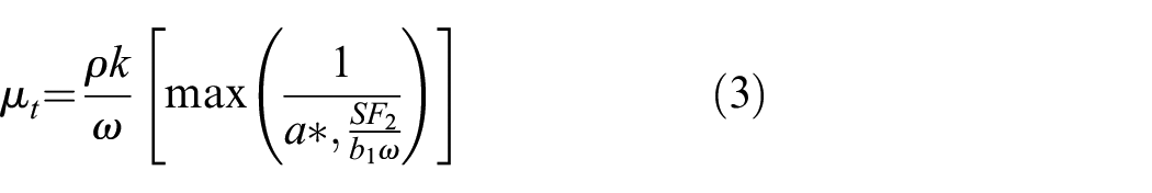
where S is the strain rate magnitude, a* is the coefficient which damps the turbulent viscosity causing a low-Reynolds-number correction, F2 is the blending function, and b1 is a constant.
The constants in the model are set to the following values 30 :
σk,1 = 1.176, σx,1 = 2.0, σk,2 = 1.0, σx,2 = 1.168, b1 = 0.31, bi,1 = 0.075, and bi,2 = 0.0828.
Boundary conditions of the simulations are set according to the working principle of the spool valve. The pressure of inlet port is set to be 1.2 MPa, which is the line pressure of the hydraulic system. The outlet pressure increases from 0 to 0.9 MPa with step size 0.1 MPa while the opening of inlet port xg increases from −2 mm to 5 mm with step size 0.5 mm to analysis pressure-flow characters of the valve under different working condition. While in the simulations of exhaust port, the outlet pressure increases from 0.1 to 1.2 MPa with step size 0.1 MPa while the opening of exhaust port increases from 0.1 mm to 2.5 mm with step size 0.1 mm. The solution accuracy is set to be 10−5, and hydraulic oil with viscosity of 46 cSt and density of 860 kg/m3 is chosen as the fluid medium.
CFD results
Figure 4 shows an example of the resulting pressure and velocity distribution contours of the flow field in the symmetry plane corresponding to valve opening xg = 1 mm and output pressure pout = 0.1 Mpa. The flow velocity increases rapidly in the throttle area because of the sudden reduction of flow area. A vortex can be formatted by the mutation of jet velocity in the area between inlet port and output port and leads to pressure decreases and energy dissipation in the flow channel. The jet velocity differs along the circumference of throttle area. The maximal jet velocity appears in the throttle area near the output port. Correspondingly, circumferential pressure losses occur and lead to the pressure difference between output chamber and feedback channel. On account of larger throttling area, the flow velocity in valve with chamfer and U shape notches are larger than the one with normal spool geometry. The pressure in the feedback channel of valve with chamfer is larger than the one with U shape notches, while the one using normal spool is the least.
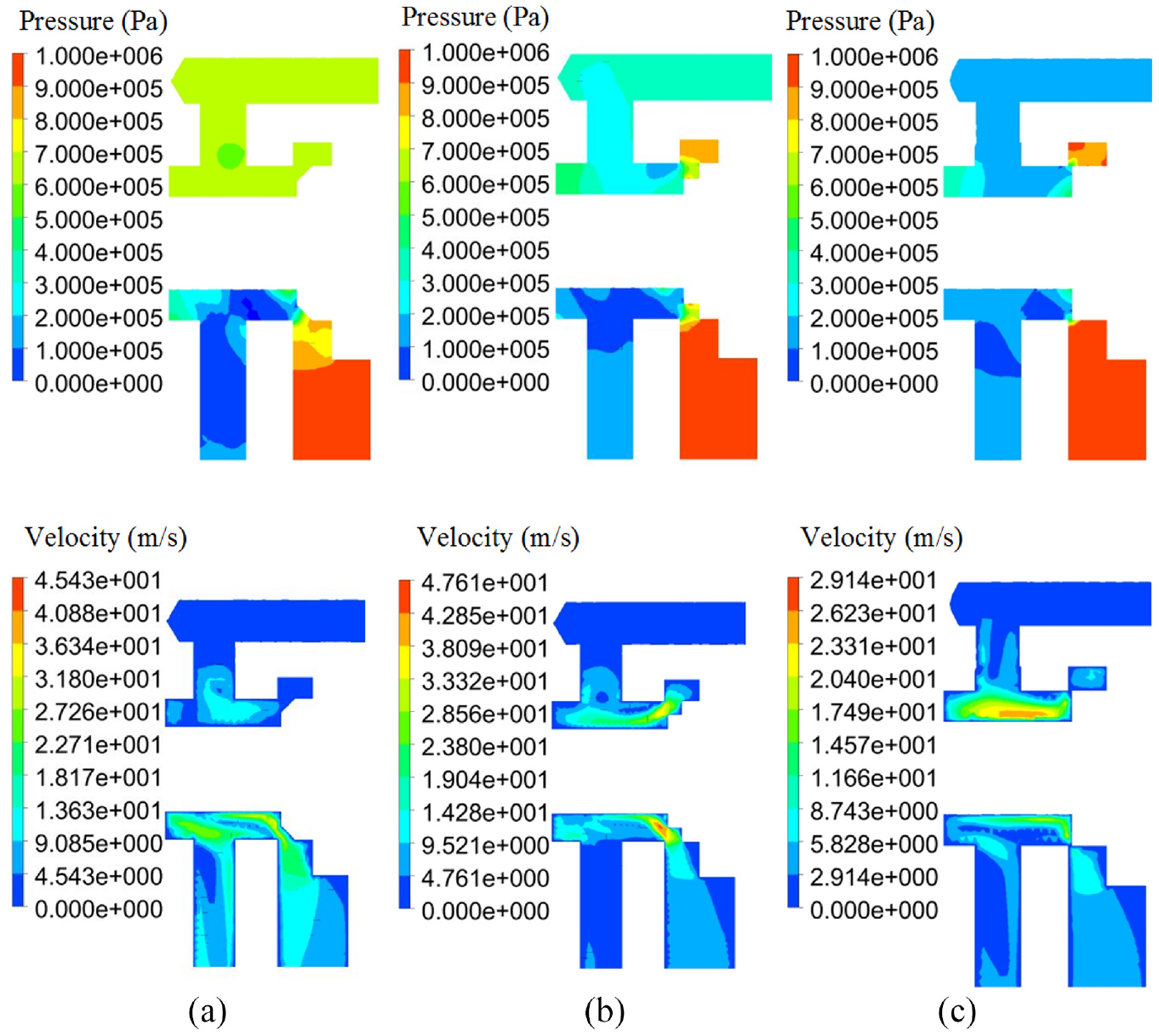
Pressure and velocity distribution at symmetry plane: (a) with chamfer, (b) with u notches and (c) without notch.
The calculated flow rate of three kinds of valve spool corresponding to different valve opening and pressure difference between inlet and outlet pressure are calculated and shown in Figures 5 and 6. The valve with chamfer and u shape notches start to increase since valve opening xg is larger than −2 mm. The flowrate is determined by the flow area, which is related to the shape of notches when valve opening is negative. The flow rate of valve with chamfer increases nearly linearly during the whole opening process, while the flow rate of valve with u shape notches increases slower when xg is negative than xg is positive. The maximum flow rate of valve with normal spool is 172.7 L/min, while the one with chamfer is 172.8 L/min and the one with u shape notches is 184.8 L/min, which indicate the spool with chamfer can enlarge the spool stroke adjustment range but cannot increase the maximal flowrate while spool with u notches can increase the maximal flowrate of valve and enlarge the spool adjustment range.

Simulation results of flow rate under different valve opening and pressure difference.

Simulation results of the inlet flow rate under pressure difference of 0.9 Mpa.
The CFD simulation results of the exhaust flow rate is shown in Figure 7. The slope of the flow rate decreases when the valve port opening is larger than 1 mm, which is similar with the results of the inlet port and affected by the internal flow path section area.
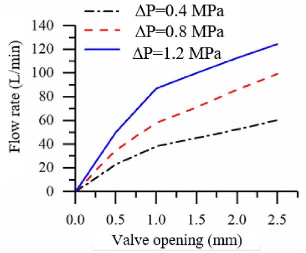
Simulation results of the exhaust flow rate under different valve opening and pressure difference.
The static axial flow force of the valve spool can be calculated by software ANSYS, which is composed of pressure force and viscous. The flow force along the x axes can be calculated by equation (4).

where nx is the unit vector of the x axes, Fp is the vector of pressure force, and Fv is the vector of viscous force.
Figures 7 and 8 show the comparison of the calculated values of axial steady flow force of the inlet port with different valve openings and pressure difference. The maps of axial flow force corresponding to different valve opening and pressure differs because of different flow characters of three different spool geometries. The minimum axial flow force of spool with u notches is −15.4 N, which is tend to close the valve inlet port, while the minimum axial flow force of spool with u notches is −18.8 N, the force of normal spool is −22.4 N.

Simulation results of axial flow force of the inlet port with pressure difference of 0.9 Mpa.
The steady flow forces appear to increase in the negative direction at small valve opening, which tend to close the valve while for further increasing valve opening, the flow force increases in the positive direction. This appearance can be explained by the velocity contours corresponding to different valve openings shown in Figure 7 and the calculation equation of flow force basing on the momentum theory:
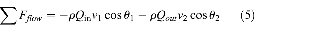
where

CFD results of output flow angle with increasing valve opening.
Figure 10 shows the simulation results of the flow rate steady flow force of the exhaust port with different valve opening and pressure difference. Unlike the axial flow force of the inlet port, the axial flow force of the exhaust port increases with the increase of the valve opening and the pressure difference.

Simulation results of axial flow force of the exhaust port with different pressure difference.
Dynamic modeling of the system
In this section, state equations of the hydraulic system are established basing on the CFD simulation results and mathematical model of the system in our previous study.25,26 The CFD simulation results of valve flow rate and axial flow force are utilized to modify the model.
The dynamic model of the system in the previous study is expressed as:
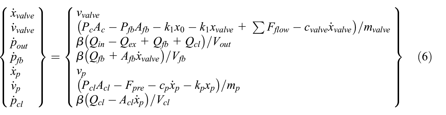
where mvalve is the mass of the spool, xvalve is the displacement of spool, cvalve is the spool damping coefficient. Ac and Afb are the section area of the left and right end on the spool. x0 represents the constant pre-compression of valve spring, k1 is the valve spring rate. The axial flow force acting on the spool here are expressed as the combination of flow force of the inlet port and the exhaust port calculated by the CFD results in Section 3. β is the bulk modulus of the fluid, Vout and Vfb are the volume of output and feedback chamber. xp is the displacement of the piston, mp is the mass of piston, Fpre is the preload of piston spring, cp is the damping coefficient of piston, kp is the spring rate of piston. The inlet and exhaust flowrate Qin and Qex of three kinds of valve geometry are calculated by the CFD simulations, while the others can be calculated by commonly used discharge formula of sharp edge spool valve port and orifice and can be expressed as:


where Cd is the discharge coefficient of the orifice hole and ρ is the density of hydraulic fluid, rori1 and rori2 denotes the radius of orifice1 in the feedback fluid path and orifice2 in the fluid path to the piston chamber shown in Figure 1. The parameters and the dynamic model with the normal spool has been verified in the previous studies.23,24
Bifurcation analysis
Bifurcation analyses are carried out to study the influence of different spool geometry on the stability of the system.
One parameter bifurcation analysis
One parameter and two-parameter bifurcation calculations are carried out basing on the proposed mathematical model in this section to study how different spool geometry affect the stability of the system.
Set plane vvalve = 0 as Poincare plane. Set Pc = 0.3 Mpa. A one-parameter bifurcation diagram can be calculated by varying parameter dori1 from 1 to 7 mm. It can be seen from the figure that the equilibrium point of systems using valve spools with chamfer and u shape notches while the equilibrium point of the system with normal sharp edge spool is varied due to different flow character of valve spools. As presented in Figure 11, three bifurcation trajectories denote the displacement of three kinds of spool with different geometries. When the orifice diameter is above the bifurcation point, there are two points correspond to each orifice diameter in the figure, which represent the maximum and minimum displacement of the spool. The vibration amplitude of the spools increase when the orifice diameter is increased. The bifurcation point corresponding to systems using u shape notches and normal shape edge spool are dori1 = 2.6 mm and dori1 = 4.4 mm. The bifurcation of system using spool with chamfer occurs when dori1 = 1.4 mm, which means this spool geometry need the smallest orifice diameter to keep the system stable.

One parameter bifurcation diagram.
Two parameter bifurcation analysis
To explain how these spool geometries affect the stability boundary in the (Pc, dori1) parameter plane, two parameter bifurcation diagrams are computed with different orifice diameter and pilot pressure in the simulation models with three kinds of spool geometries. The calculated curve shown in Figure 12 represents the stability boundaries for system with three kinds of spool in the parameter plane, which means the system is stable with parameters below the curve and unstable with parameters above the curve. For increasing pilot operating pressure Pc, the bifurcation point of orifice diameter corresponding to different pilot pressure decreases to a critical minimum value and starts to increase after the corresponding pilot pressure. The stable region of system using normal sharp edge spool is larger than the others while the stable region of system using u shape notches is larger than the one using spool with chamfer.
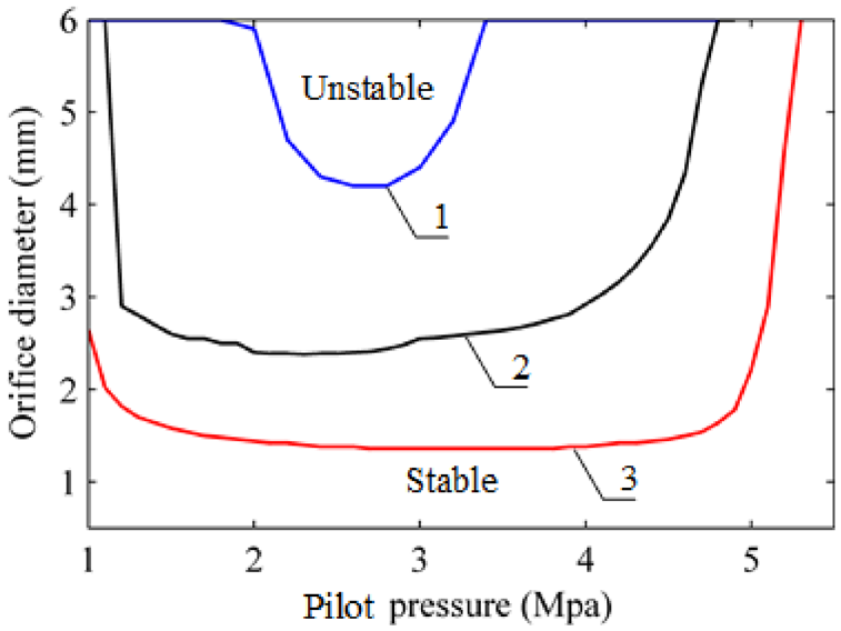
Simulation results of stability boundary; (1) stability boundary of valve with normal spool; (2) stability boundary of valve with u notches; (3) stability boundary of valve with chamfer.
Numerical simulation
To analysis the dynamic behavior of the system in the stable and unstable region of the parameter space, simulations are performed. Set dori1 = 3 mm, Pc = 0.3 Mpa. The time history of three kinds of valve spool displacement and FFT results are shown in Figure 13. The transient time of valves with three kinds of spool varies due to different force and flow characters of spool geometries, among which valve with chamfer need the least time while the valve with normal spool need the most time. The system with normal spool is stable after transient, the valve displacement converges to an equilibrium point, while the systems with u shape notches and chamfer exhibit as sustained oscillation after the transient. The oscillation interval of the two spools are different due to different force and flow characters, which is identical with the bifurcation diagram. The oscillation frequency of the two valves can be seen in the FFT results. The frequency of valve with chamfer is nearly 230 Hz, larger than the value 195 Hz corresponding to the one with u notches.

The time history and FFT results of pressure response with different spool geometry.
Conclusion
In this paper, Computational fluid dynamics (CFD) simulations of flow force and flow rate under different pressure difference and valve openings were proposed to obtain the pressure-flow characters of flow field inside valves with different spool geometries. The CFD simulation results reveal that the maximum flow rate of spool with u shape notches is nearly 7% larger than the others and the maximum flow force of spool with u shape notches is the least among the three valve spools, while the value with normal spool have the largest flow force. Bifurcation analysis results indicate that the stable parameter region of system using normal sharp edge spool is larger than the others while the stable region of system using u shape notches is larger than the one using spool with chamfer. Numerical simulation results indicate that the valve with u notches can achieve a faster dynamic response character because of the larger flow rate and less flow force acting on the spool, however, the stable parameter region of valves can be reduced and nonlinear bifurcations can be born during the working process of the valve and lead to unexpected vibrations. Special attentions should be paid by valve designers to consider the tradeoff between dynamic response character and stability of the system considering different application conditions. This could provide important instructions to the designers of hydraulic actuator system. Further work will include the stability study of pressure control valve with different spool geometries considering two phase flow.
Footnotes
Handling Editor: Chenhui Liang
Declaration of conflicting interests
The author(s) declared no potential conflicts of interest with respect to the research, authorship, and/or publication of this article.
Funding
The author(s) disclosed receipt of the following financial support for the research, authorship, and/or publication of this article: This research is supported by the Young Elite Scientist Sponsorship Program by China Association for Science and Technology.