
Abstract
Optical free-form surface elements have better optical characteristics than traditional optical elements, but their more complex curved structure also increases the difficulty of optical processing. Aiming at the problem of insufficient equal overlap ratio spirals, this paper proposes a polishing trajectory planning method for the optimal removal of the full surface. Based on the overlap length model of the curvature change, the polishing area, track residence time and total material removal model are established, and the processing efficiency is determined. The projection method is used to map the spatial polishing trajectory to the plane, and the mathematical relationship between the material removal amount and the trajectory spacing of the circular polishing and the projection trajectory spacing is established. This paper analyzes the influence of contact area change, geodesic radius of curvature and polishing posture on the material removal of the curved surface, as well as the change trend of the material removal contour and the contour of the overlapping part. Finally, taking the rotationally symmetrical aspherical workpiece made of K9 glass as an example, the corresponding polishing plan is formulated to verify the effectiveness of the proposed method.
Introduction
In recent years, optics has crossed and merged with other disciplines and technologies to open up new scientific research and application fields. 1 Optical curved surfaces have gradually developed from traditional flat and spherical surfaces to aspherical and free-form surfaces. According to the requirements of the optical system, free-form optics breaks the traditional optical imaging method, thus the corresponding optical curved surface is designed and constructed. 2 It has the advantages of simplifying the structure of the optical system, correcting aberrations, improving the quality of optical imaging, reducing the number of system units, and improving the optical design. There are many advantages such as spatial layout, reducing the cost of the optical system increasing the degree of freedom of the system, and expanding the field of view et etc. Therefore, the application and demand of optical free-form surface components are gradually increasing. However, due to the complexity and irregularity of optical free-form surfaces, it is difficult to build mathematical analysis models on free-form surfaces, and it is also more difficult to process and detect. 3 As the final process of optical curved surface manufacturing, the polishing process accounts for about 60% of the entire manufacturing process time. Although the polishing efficiency is low and it takes a long time, still it has a great impact on the quality, accuracy, optical performance and service life of the optical components.
Computer Controlled Optical Surfacing, referred to as CCOS, is based on the surface inspection results to quantitatively simulate the polishing machining allowance, 4 and use computer technology to control the small tool head to move on the surface of the workpiece with a preset trajectory. This technology determines the parameters such as polishing pressure, feed speed and residence time distribution, 5 and use numerical control (NC) servo technology to accurately remove optical workpieces, thereby correcting surface errors and improving accuracy. Computer quantifiable control algorithms and NC machine tools have higher accuracy and repeatability, which significantly improves the surface convergence rate and processing efficiency. During optical processing, the polishing tool head needs to move along the planned polishing path. The quality of the polishing path determines the processing quality and efficiency of the workpiece. Therefore, CCOS polishing path planning is a research hotspot in the field of modern optical manufacturing.
The CCOS control algorithm directly affects the quality of optical processing, which can be divided into path planning and dwell time algorithms. 6 Commonly used trajectory planning methods are isoparametric line method, projection method, equal residual height method, equal plane method, polyhedron method, offset surface method, equal residual height method and Peano trajectory. Isoparametric method7,8: The mathematical model has two parameters, one parameter value is fixed, and the other parameter is changed to generate the processing trajectory. Because of the small amount of calculation, the isoparametric method can quickly generate processing trajectories, so it can improve efficiency and be widely used, but this method is only applied to workpieces with a large radius of curvature. Isoplane method9,10: The intersection of the parallel plane and the surface of the workpiece are used as the processing track. This method is suitable for processing curved surfaces with uneven distribution of parameter lines, and can generate uniform processing trajectories, but the process of solving the intersection lines between the plane and the curved surface is very cumbersome. Parallel projection method: Project the processing trajectory of the plane to the surface of the workpiece. This method is suitable for workpieces with large changes in the curvature of the surface. The track spacing can be adjusted actively according to the curvature. It is not suitable for free-form surfaces with complex surface changes. Polyhedron method 11 : Approximate the machined surface in the form of a polyhedron with a certain accuracy. Most polyhedrons are usually composed of triangular mesh surfaces, and then the intersection of the parallel plane and the polyhedron is used as the processing track. This method simplifies the surface structure and improves the processing efficiency, but it will reduce the machining accuracy of part of the curved surface. Equal residual height method7,12,13: Regard the residual error between adjacent tracks as a quantification, by adjusting the track spacing, the processing accuracy and efficiency can be optimized. This method can adjust the processing trajectory according to the surface shape of the curved surface to ensure the processing quality, but the overall calculation is complicated and takes a long time. Offset surface method14,15: Combining the characteristics of the spherical knife, offset the contact points of each tool on the machining surface to obtain the tool location point, and then obtain the tool location surface, and carry out trajectory planning on the tool location surface, and the offset distance approximately equal to the radius of the spherical knife. The processing trajectory of this method will not cause local interference, but it also increases the difficulty of solving due to the increase of the tool position surface. Peano trajectory16,17: Peano curve is a non-differentiable curve, which is the limit of a curve sequence. It can fill up the two-dimensional or higher-dimensional space through any point in the two-dimensional area. It can give full play to the advantages of small tool head polishing and have a better anastomotic type and coverage.
However, trajectory planning research is mostly in the field of milling processing. In the polishing field, Mizaugaki et al. 16 applied the Peano curve to the polishing field. Tam et al.17,18 improved the grating path, Lissajous curve and Peano curve by using the line spacing adaptation algorithm to improve the coverage and uniformity, and transformed the Peano curve to make it more suitable for aspheric machining. The helix path is very suitable for the processing of rotating aspheric surfaces,19,20 but the helix path may over process the workpiece in the central part. Regular polishing tracks are easy to leave regular scratches on the workpiece, which is the main source of high-frequency error of the workpiece. 21 In order to solve this problem, Dunn and Walker 22 proposed to use pseudo-random path polishing. Shi et al. 23 proposed random trajectory polishing. Deng et al. 24 proposed a new path planning method for off-axis aspheric NC polishing based on the idea of weighted average. Jin et al. 25 introduced the bisection algorithm into path planning for the optimization of line spacing.
There is still a lot of room for development in the types and maturity of trajectory planning methods. Therefore, this paper proposes a polishing trajectory planning method for the optimal removal of the entire surface. Based on the overlap length model of the curvature change, the polishing area, track residence time and total material removal model are established, and the processing efficiency is determined. The projection method is used to map the spatial polishing trajectory to the plane, establish the mathematical relationship between the material removal amount and the trajectory spacing of the annular polishing and the projection trajectory spacing, analyze the influence of the contact area change, the geodesic curvature radius and the polishing posture on the material removal of the curved surface, and the material removal change trend of contour and overlapping part contour.
The effect of track spacing on material removal
Spatial polishing trajectory and projection trajectory
The structure of optical free-form surfaces is complex and changeable, and it is difficult to directly generate tool trajectories on the surface of the workpiece. In this paper, the parallel projection method is used to combine the spatial curve trajectory of the workpiece surface with the projected trajectory in order to analyze and calculate the spatial polishing trajectory.

Draw a perpendicular line to the surface O-xy through each point on the curve C to obtain the projected plane curve:

As shown in Figure 1, rotational symmetry aspheric surface with a curved surface of

Rotational symmetry aspheric surface with a curved surface, including (a) 3D graph and (b) projection on O-xy.
The influence of polishing track spacing on material removal
When the polishing tool head is polished along the circular track, the overlapping part of the adjacent track spacing will be polished twice, thus affecting the removal of material (Figure 2) . Figure 3 is a schematic diagram of Figure 2 in the plane O-xz direction, that is, when θ = 0, h1(ρ) changes in dθ. ai and ai+1 are the radius of the contact circle of the polishing track. Since the radius of curvature of the surface of the workpiece is much larger than the radius of the tool head, the material removal of adjacent tracks is basically the same, so the radius of the contact circle can be approximated as a fixed value, that is, ai = ai+1 = a, si is the distance between adjacent tracks, which can be regarded as the distance between the center points of the contact circle. Since the material removal model at the repeated polishing is approximately an axisymmetric figure, the overlap length is 2ri. When 0 < ri < a, adjacent tracks are over-polished.

Schematic diagram of the polishing track of the contact surface.

Schematic diagram of material overlap removal.
The adjacent track spacing si of annular polishing is

In the dθ plane, the relationship between the amount of material removal and the overlap length ri is:
In the dθ plane, the relationship between the amount of material removal and the spacing ri is:
Taking the surface shape
Polishing process parameters.
Figure 4 shows the relationship between Δh1(ρ) and ri based on equation (4). With the increase of overlap length ri, Δh1(ρ) increased nonlinearly. Because the width of the polishing path is much smaller than the radius of the small tool head and the workpiece, the relationship between the amount of material removed and the overlap length between the paths is nearly linear. Figure 5 shows the relationship between Δh1(ρ) and si based on equation (5). When 0 < si < 2a, as si increases, Δh1(ρ) decrease, that is, the amount of material removed decreases with the increase of track spacing. When si ≥ 2a, it means that there is no repeated polishing between adjacent tracks, and there is no material removal in the overlapping part.

Δh-ri Relationship diagram.

Δh-si Relationship diagram.
Relationship between polishing trajectory and projection trajectory
The distance between the curved surface polishing tracks is very small, so the distance between any two points on the adjacent tracks can be regarded as a straight line distance. Points Pi and Pi+1 are two points on adjacent trajectories, and the coordinates are (xi, yi, zi) and (xi+1, yi+1, zi+1), then the surface trajectory spacing si is:

In the plane of O-xz, this formula can be simplified to:

The projected trajectory distance li = xi+1−xi the relationship between the projected trajectory distance li and the overlap length ri is:

According to the actual polishing surface shape, the relationship between the material removal amount of the second polishing of the overlapping part and the projection track pitch is established. As shown in Figure 6, when r = 0.25a and r = 0.4a, along the x-axis direction, the increase in surface curvature results in a change in contact circle a. Although there is a decreasing trend in the distance between curved tracks, the change of r and curvature affects a little change, which verifies the Greenwood theoretical model. Since the curvature of the geometrical surface has a great influence on the projection of the rotationally symmetrical aspheric surface, the distance between the projected trajectories gradually decreases with the increase of the abscissa x, so the choice of the actual polishing workpiece has a great influence on the change of the projected trajectory distance.

Schematic diagram of the change of the projection track pitch.
Factors affecting the material removal of the rotationally symmetric aspheric surface
Factors such as the contact area and the curvature of the workpiece affect the removal of material. Therefore, it is necessary to analyze and optimize the influence of these parameters before establishing the residence time of the rotationally symmetrical aspheric surface and the total amount of material removal.
Impact of changes in contact area on material removal
When a spherical tool head is used to polish a workpiece, the change in the surface curvature of the workpiece affects the polishing contact area, so it is necessary to analyze the relationship between the amount of material removal and the change in curvature. In the experiment, a spherical tool head of polyurethane and a rotationally symmetrical aspherical workpiece
Experimental simulation parameters.

Under the same experimental conditions, the polishing inclination angle, the polishing deflection angle and the geodesic curvature radius are constants, and the influence of the changes in the contact area of the three surface shapes on the amount of material removal is analyzed. Figure 7 shows the polishing results of the small tool head on three kinds of workpieces. It can be seen that the larger the radius of curvature of the workpiece surface, that is, the smaller the curvature change, the smaller the change in material removal. The change range of the material removal amount of the face workpiece

Schematic diagram of the relationship between material removal and contact area.
The radius of curvature of the workpiece surface is larger than the radius of the tool head, and the change of the contact area affected by the change of curvature has little effect on the material removal. Therefore, when the trajectory planning is carried out in this paper, the change of the contact area is taken as the average value and taken as the fixed value.
Influence of geodesic curvature radius on material removal
As shown in Figure 8, suppose p is any polishing point of curve c on the space surface s, the unit tangent vector of curve c, k is the curvature vector,

Geodesic radius of curvature.
When the spherical tool head moves on the surface of the workpiece, the relative position and curvature of the polishing point Pi on the surface of the workpiece change from time to time, that is, the position and curvature of the corresponding point on the generatrix of the rotationally symmetric aspheric surface change. The relative position and curvature of the polishing point Pi determine the geodesic curvature center point Oi and the geodesic curvature radius Ri of the polishing track, so it is necessary to analyze the influence of the geodesic curvature radius on the material removal. Ri is related to the surface shape function of the actual workpiece, the relative position and curvature of the polishing point Pi. The relationship between the curvature λ and the geodesic radius of curvature Ri is:

The shape function of the rotationally symmetric aspheric surface is z(x, y) = k(x2+y2), k is the parameter that controls the shape of the surface, and its generatrix is z(x) = kx2, then the relative position of the polishing point Pi and Ri The relationship is:

When studying the influence of geodesic curvature radius on material removal, three kinds of workpieces
Relationship between material removal and geodesic radius of curvature.
As the ratio of the radius of curvature of the workpiece surface to the radius of the spherical head increases, the amount of removal changes gradually decreases. When the ratio of the two is ∞, the surface of the workpiece is approximately flat. At the same time, the choice of polishing inclination angle φ and deflection angle β has a great influence on the result of removal. Therefore, it is necessary to optimize Ri,φ and φ and perform error compensation to reduce the overall change in material removal.
Polishing trajectory planning method for the optimal removal of the entire surface
After determining the influence of the contact area change, geodesic radius of curvature and polishing posture on the material removal of the curved surface, the mathematical relationship between the amount of material removal and the track spacing and overlap length of circular polishing is combined. For plane and rotationally symmetric aspheric surfaces, a planning model of concentric circle trajectories is constructed.
Application of concentric circle trajectory planning
The optical processing polishing head movement track is usually grating track and spiral track, but these two common path movement tracks are prone to iterative errors. Archimedes spiral trajectory is a commonly used processing trajectory for rotationally symmetric aspheric surfaces. As a constant velocity spiral, its trajectory is continuous and changes smoothly. However, the curvature change of the workpiece surface will affect the change of the polishing track pitch, that is, the position on the workpiece where the curvature change rate is small, the polishing track pitch is dense, and the curvature change rate position is sparse, and even the tracks do not overlap. The corrected equal overlap ratio spiral line can stabilize the polishing track distance because the overlap portion of the track pitch is equal, but for workpieces with large curvature changes, the optimal overlap ratio between the tracks on each surface is different. Therefore, the equal overlap rate method cannot cope with the problem of curvature changes, and at the same time cannot quantify the residence time distribution, the total amount of material removal and the processing efficiency. Based on this, a concentric circle trajectory planning method with variable spacing is proposed.
Concentric circles are mathematically defined as circles with the same center but different radii on the same plane. In actual polishing, the concentric circle track has the advantages of easy track pitch adjustment and smooth track, thereby improving the polishing efficiency. The equation is

Equation (11) represents any circle with a point (a, b) as the center and a positive radius. Any circle is symmetrical and continuous. Therefore, when using a concentric circle track for material removal, it is only necessary to select any direction with the center of the circle as the origin for analysis. On the plane, the point (0, 0) is taken as the center of the circle. When Ri ≤ a, the periphery of the center will be over polished. When Ri > a, the material removal equation of the concentric circle track is:

The above formula is a function with ρ as the independent variable and Hi(ρ) as the dependent variable. The equation also includes parameters such as the polishing inclination angle φ, the polishing deflection angle β, and the geodesic curvature radius Ri. Therefore, in actual engineering, these parameters need to be optimized.
Figure 10 shows the polishing process of the tool head on a flat workpiece using concentric circular trajectories. Any circular polishing trajectory in the concentric circular trajectory is i, where Ri is the radius of the trajectory i, and the value range of ρ is (ρimin, ρimax). The distance between the polishing tracks i and i+1 is si, and the overlap length is 2ri, then:

Material removal of flat workpieces.
ri is a function related to the overlap length in actual polishing. When the workpiece is a flat surface, ri is a fixed value; when the workpiece is a rotationally symmetric aspheric surface, ri can be a linear function or a non-linear function, and the track spacing can be actively adjusted according to the curvature of each area of the workpiece. Therefore, during specific polishing, the relationship between the position x and the overlap length ri can be established according to the track spacing with the smallest roughness at the positions with different curvatures and the processing efficiency of the polished workpiece.
Polishing trajectory planning for the optimal removal of the plane
When the workpiece is close to the plane, the geodesic radius of curvature R is equal to d, and the specific steps of concentric circle trajectory planning are: when R ≤ a, use fixed-point polishing. When R > a, the material removal model of track 1 is H1(ρ) = 2πR1h1(ρ), and the material removal model of track 2 is H2(ρ) = 2πR2h2(ρ). According to simulation and experimental results, at different positions on the surface of the workpiece, when the surface roughness is optimal, the overlap length ri between the corresponding tracks is measured. The overlap length of trajectories 2 and 1 is denoted as r1, and the overlap length between the outermost trajectories is denoted as rn. Since the curvature is unchanged or minimal, the overlap length ri is a constant or a linear function:

The amount of material removal in the overlapping part of polishing track 2 and 1 is:

The distance between polishing track 2 and 1 is s1 = R2 − R1 = 2(a−r1), the material removal model of polishing track i is Hi(ρ) = 2πRihi (ρ), and the material removal model of polishing track i+1 is Hi+1(ρ) = 2 πRi+1hi+1(ρ). The material removal amount of the overlapping part of the polishing track i and i+1 is:

The distance between polishing track i and 1 is:

Since the overlapping length of the polishing track n+1 and n is rn, the radius Rn+1 of the polishing area of the workpiece is:

Therefore, in determining the polishing range Rn+1 of the polishing workpiece, the number n of polishing tracks of the flat tool can be known. Then the theoretical material removal total of the polished workpiece is

Polishing trajectory planning for the optimal removal of rotationally symmetric aspheric surfaces
Figure 11 shows the polishing situation of a spherical tool head on a rotationally symmetric aspheric surface z(x, y) = k(x2+y2) with concentric trajectories. The polishing points Pi and Pi+1 are any points on the polishing trajectories i and i+1, respectively, and the distance from the points Pi and Pi+1 to the center of rotation, that is, the radius of curvature of the polishing trajectory is di and di+1. Because of the curvature change, make the tangent planes of points Pi and Pi+1 respectively, where Ri and Ri+1 are the geodesic curvature radii of points Pi and Pi+1.

Schematic diagram of material removal of rotationally symmetrical aspherical workpieces.
When the workpiece is a rotationally symmetric aspheric surface, the change in curvature λ affects the material removal parameters. When R > a, the material removal model of track 1 is H1(ρ) = 2πR1secλ1h1(ρ), and the material removal model of track 2 is H2(ρ = 2πR2secλ2h2(ρ).
Due to the change of curvature, different positions on the surface of the workpiece reach the ideal surface roughness, and the overlap length ri between the tracks of the corresponding positions is obtained. In a rotationally symmetric aspheric surface, ri and the curvature λ function r(λ) can be established by an iterative method, or a linear or non-linear function of ri and the number of trajectories i can be established by experimental detection.
The material removal amount of the overlapping part of polishing track 2 and 1 is:

The distance between polishing tracks 2 and 1 is
The material removal amount of the overlapping part of the polishing track i and i+1 is:

Since the overlapping length of the polishing track n+1 and n is rn, the radius dn+1 of the polishing area of the workpiece is:

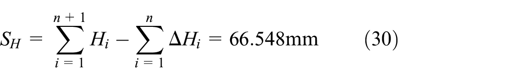
When the radius of curvature of the workpiece surface is larger than the radius of the tool head, the contact circle radius ai is approximately a, and the polishing area range dn+1 of the workpiece is determined, and the number of rotationally symmetric aspheric polishing tracks n can be obtained. The total material removal model of the rotationally symmetric aspheric surface is SH.
Trajectory planning simulation of optimal removal of rotationally symmetric aspheric surface
Archimedes spiral simulation
A spherical tool head made of polyurethane was used to polish the K9 glass plane workpiece. Under the experimental conditions in Table 3, the polishing contact circle radius a = 1.465 was obtained.
Contact circle radius a determines the experimental parameters.
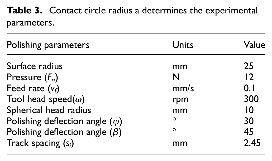
Figure 12 shows the Archimedean spiral with si < 2a on the workpiece surface
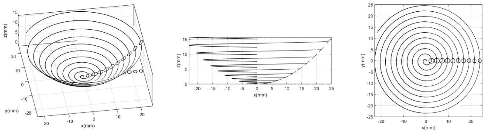
Simulation diagram of Archimedes spiral.
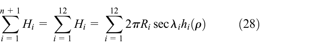
Overlap length model based on curvature change
The hi(ρ) and Δhi(ρ) of the polishing track i of the rotationally symmetrical aspheric surface change with the curvature λi, and the ideal track spacing si is different in regions with different curvatures. Therefore, the ri of the different curvature positions of the workpiece surface shape

Experiments have found that when the overlap length ri > 0.5a, the material removal contour Δhi(ρ) of the overlapped part will generate a new material removal contour, and then repeat:

As shown in Table 4, when trajectory 1 is 0.05a < r < 0.25a, the depth difference between h1 and h1′ is Δh1 < 0, that is, the lowest point h1′ of the overlapping part of Δh1(ρ) removed from the contour is higher than h1(ρ) material removed the lowest point h1 of the contour. When 0.25a < r < 0.3a, Δh1 changes from negative to zero and then to positive. Therefore, when the maximum material removal required by the workpiece does not exceed 0.1 mm, the ideal overlap length range between trajectories 1 and 2 is (0.25a, 0.3a). When 0.3a < r < 0.5a, Δh1 > 0 and the value of h1 gradually increase, that is, the amount of material removed from the secondary polishing of the overlapping part is greater than h1(ρ) of polishing track 1, and when r = 0.45a, polishing, the right half of the removed contour of trajectory 1 basically disappears. When 0.5a < r < 0.75a, the track 1 gradually disappears, and when r = 0.45a, the track 1 disappears completely and becomes a smooth curve with the overlapping part Δh1(ρ). Δh1(ρ) generates a new material removal profile, then the depth difference Δh11 between h1′ and the lowest point h11′of the new profile changes from negative to zero and then to positive. When the machining allowance of the workpiece is 0.1–0.2 mm, the best range of material removal effect is (0.55a, 0.6a), and when r = 0.75a, a new material removal profile appears.
Relationship between depth difference Δhi and r.

The trajectory n is similar to n+1, when 0.05a < r < 0.3, the depth difference between hn and hn′ is Δhn < 0. When 0.3a < r < 0.35, Δh1 changes from a negative value to a positive value. Therefore, when the maximum material removal required by the workpiece does not exceed 0.1 mm, the ideal overlap length range between trajectories n and n+1 is (0.3a, 0.35a). When 0.35a < r < 0.5a, Δhn > 0, and when r = 0.5a, the right half of the removal contour of the polishing track n+1 basically disappears. When 0.5a < r < 0.75 a, the trajectory n+1 gradually disappears, and the overlapping part Δhn(ρ) becomes a smooth curve, and the depth difference Δhnn between hn′ and hnn′ produced by Δhn(ρ) changes from a negative value to a positive value. When the maximum material removal of the workpiece is 0.1–0.2 mm, the material removal effect is optimal (0.6a, 0.65a), and when r = 0.75a, a new material removal profile appears.
Therefore, in actual polishing, according to the detection results of surface roughness, calculate the surface error and machining allowance of the workpiece. Combined with this experiment, when the machining allowance is about 0.1 mm, the overlap length is selected in the range of 0.25a−0.35a. When the machining allowance is about 0.2 mm, the overlap length is 0.55a–0.65a. In order to meet the surface accuracy and processing efficiency, the correct value r must be taken.
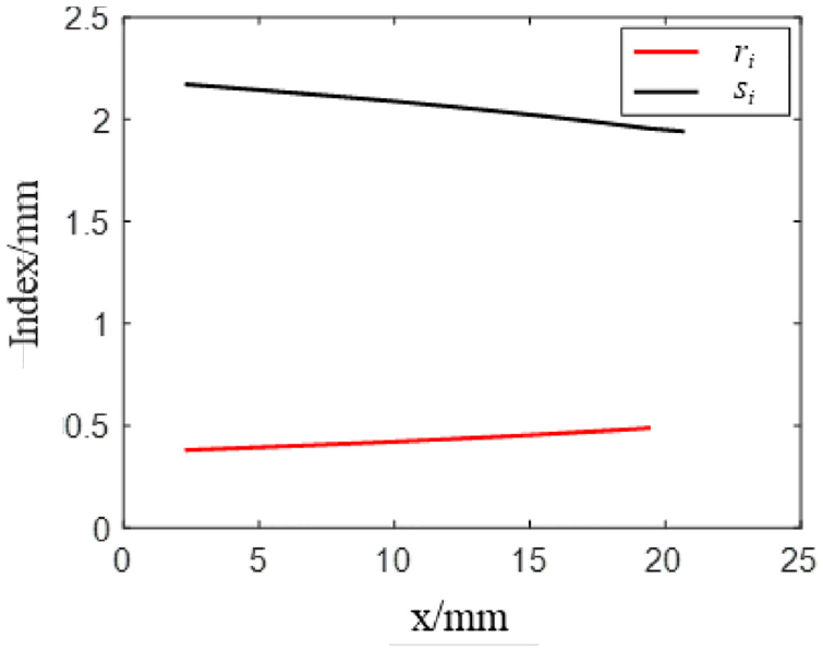
As shown in Figure 13, when the amount to be removed on the workpiece surface is about 2 mm, the concentric circle track with an overlap length of 0.65a is a schematic diagram of the polishing track along the surface O-xz. The radius is from 0 to 25 mm, and the material removal of the polishing track changes with the increase of x. And change. The red trajectory line is the polishing trajectory i, and the black contour line is the material removal contour of the overlapped part of the secondary polishing. When r > 0.5a, the secondary polishing trajectory generates a new contour, which is specifically expressed as a wave trough. Figure 14 is a 3D schematic diagram of the polishing track of Figure 13.
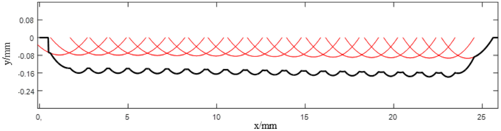
Schematic diagram of polishing track r = 0.65a.

Schematic diagram of polishing track in 3D r = 0.65a.
In actual processing, when the error between the surface of the workpiece to be polished and the theoretical model is around 0.1 mm, the r value ranges of track 1 and n+1 are (0.25a, 0.3a) and (0.3a, 0.35a), respectively. The value of r is optimized, as shown in Figures 15 and 16, when r = 0.259a and r = 0.333a, the depth difference is approximately zero.

Schematic diagram of 0–5 mm with r = 0.259a.

Schematic diagram of 20–25 mm with r = 0.333a.
In the surface of the workpiece

As the area to be polished increases, such as the radius of 30, 40,and 50 mm, etc., or the curvature of the workpiece surface changes more, the advantage of this controllable track pitch will become more obvious. According to the value of ri at different positions of the curvature, a corresponding functional relationship is established, so as to precisely control the change of the polishing track pitch and better cover the surface of the workpiece.
Trajectory planning simulation of optimal removal of rotationally symmetric aspheric surface
The concentric circle trajectory planning optimizes the polishing trajectory of the rotationally symmetrical aspheric workpiece by quantitatively controlling the coincidence length ri, that is, the trajectory spacing s
i
. Since the trajectory is based on the center of rotational symmetry, there will be no iterative error of the spiral line. According to the specific workpiece surface shape and polishing process parameters, the material removal SH in the polishing area, the residence time t and the polishing area model can be calculated, so as to plan the polishing trajectory of the optimal removal amount of the full surface, thereby improving the polishing quality and efficiency. As shown in Figure 17, the initial track spacing si of the workpiece

Schematic diagram of concentric circle trajectory with controllable removal.
During the polishing process, both the track pitch si and the overlap length ri vary with x. As shown in Figure 18, the function relationship between overlap length ri and x. is:

Change of ri and si with x.
The function relationship between track spacing si and x is:

Since ri increases as x increases, si decreases as x increases. Considering that the maximum amount of material removal does not exceed 1 mm, the overlap length ri between tracks is small. Table 5 shows the specific values of the relative position coordinate x, the overlap length ri and the track spacing si of the polishing track i.
The specific parameters of ri, si, R and λ.

The polishing tool head moves on a rotationally symmetrical aspherical workpiece, and the curvature λi of the polishing point pi changes with x. Figure 19 is the generatrix
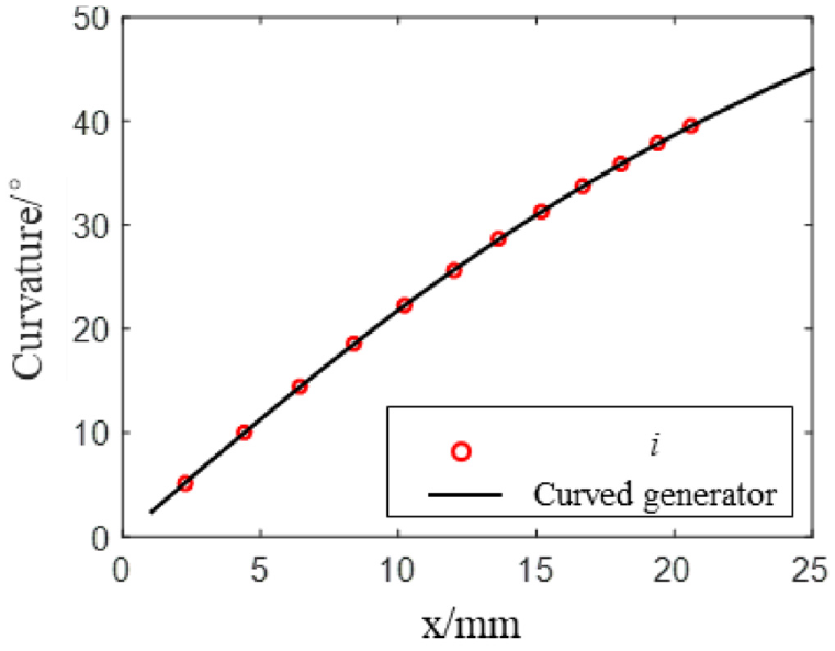
Change of λ with x.
As shown in Figure 20, the curvature λ affects the material removal of the polishing track, the curvature λ and the track spacing si affect the material removal of the overlapping part between the tracks, hi(ρ) decreases with the increase of λ, and Δhi(ρ) increases with ri and As λ increases, the corresponding hi(ρ) and Δhi(ρ) of the polishing track i are shown in Table 6.

Change of hi and Δhi with x.
The specific parameters of ri, si, R, and λ.

Many factors such as curvature λ, polishing track radius Rsc and geodesic curvature radius Ri affect the material removal amount Hi(ρ) of polishing track i. The
The

Figure 21 is a schematic diagram of the material removal amount Hi(ρ) of the workpiece

Change of Hi and ΔHi with x.
The t shown in Figure 22 is the corresponding residence times of the polishing track i of the workpiece

Schematic diagram of residence time of polishing track.
The specific parameters of ri, si, R, and λ.

Optical surface polishing and testing experiment
In order to verify the accuracy of the method proposed in this paper, an optical surface polishing and testing experiment is carried out. The experimental and testing equipment include LPS250 five-axis linkage free-form surface polishing machine (Figure 23), 2207 surface profile measuring instrument (Figure 24), which can measure and analyze the surface profile and geometric morphology of the workpiece, and OLYMPUS digital microscope DSX500 (Figure 25), which can measure the surface profile of the workpiece in 2D and 3D, convert the physical image in the microscope to digital-to-analog and directly display the enlarged picture on the display in the form of electronic signal.

Five-axis linkage free-form surface polishing machine.

2207 surface profile measuring instrument.

OLYMPUS Digital microscope.
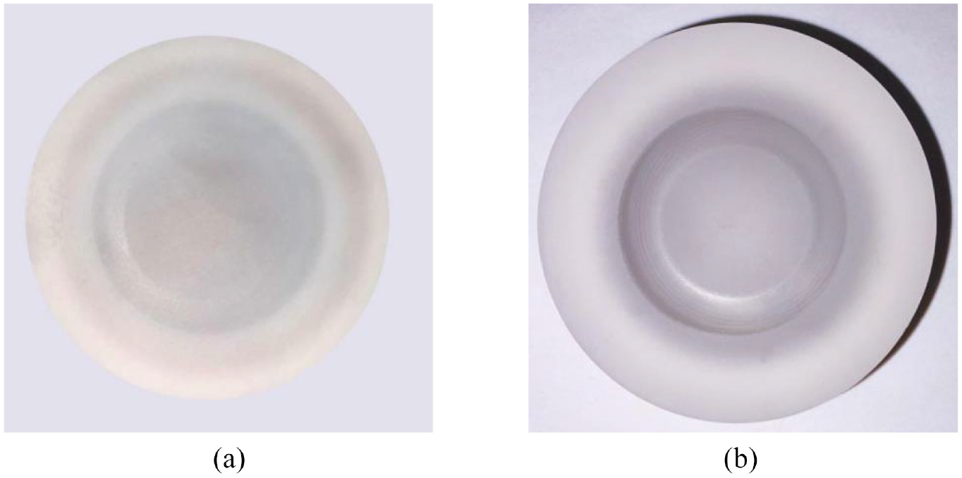
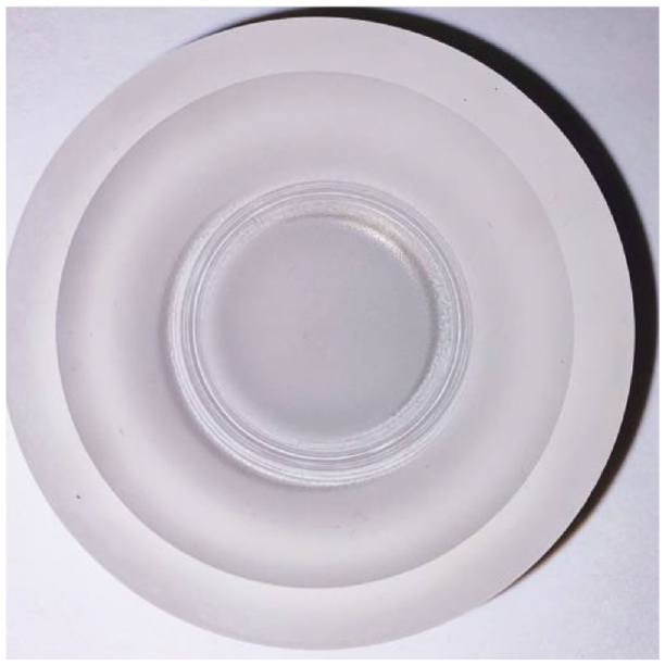
The material used in the polishing experiment is an K9 optical blank glass workpiece, as shown in Figure 26 which is approximately cylindrical in shape and about 21 mm thick. One side of the two surfaces of the workpiece is a circular plane with a diameter of about 60.5 mm, and the other side is a rotationally symmetric aspheric surface with an aspheric ring with a diameter of about 50 mm.

K9 Optical glass blank workpiece: (a) circular plane and (b) rotationally symmetric aspheric surface.
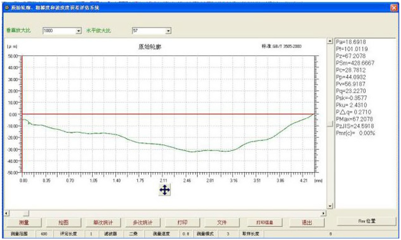
Use 2207 surface profiler to measure several points on the surface of optical glass blank workpiece. As shown in Figure 27, within the sampling length, the arithmetic average deviation of contour Ra is 2.1753 μm, and the maximum peak-valley height of roughness Rz is 15.2208 μm. Within the evaluation length, the vertical distance between the maximum peak and valley Ri is 16.8149 μm. These parameters are used as raw data, and the detection results of polishing areas are compared to check the polishing effect.

K9 Surface roughness of glass blank workpiece.
Experiment of polishing material removal in planar annular track
The distance between polishing tracks si is 1.45a, and the radii of two polishing tracks Rsc are 15 and 16.726 mm. Polishing process parameters: polishing force Fn of 5 and 10 N, rotating speed ω of 600 rpm, polishing angle φ of 30°, and residence time t of 80 min. Figure 28 shows the trajectory of the spherical tool head in the ring polishing experiment. Figure 29 is the residence diagram of a certain position in the circular trajectory polishing material removal experiment. During the processing, the polishing solution can not only cool the polishing area to ensure a constant temperature, but also the polishing particles can adhere to the polyurethane surface, reducing tool head wear and auxiliary material removal.

Tool Trajectory of LPS250 Machine Tool.
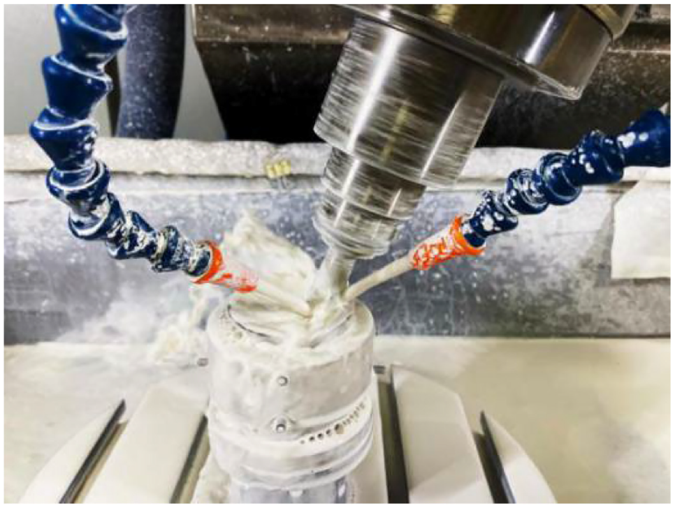
Experimental process of annular polishing material removal.
Figure 30 shows the circular polishing track of the glass plane. In the polishing experiment, the material removal in the vertical direction of the circular polishing track is approximately proportional to the polishing force, and the surface profile of any vertical direction of the circular track is approximately the same. The polishing effect of Fn = 10 N is more intuitive than Fn = 5 N.
Experimental results of glass ring polishing: (a) Fn = 5 N and (b) Fn = 10 N.
Figure 31 shows the surface profile of the circular polishing track in any vertical direction. The surface roughness of the polishing area gradually decreases from the edge to the center, and the polishing effect of the overlapping polishing area between tracks is better.

Details of two places of glass planar annular polishing: (a) Fn = 5 N and (b) Fn = 10 N.
Polishing experiment of circular trajectory of rotationally symmetric aspheric surface
In the experiment of circular trajectory polishing of rotationally symmetric aspheric surface, the pitch of polishing trajectory si is 1.4a, the radii of two polishing trajectories Rsc are 15 and 16.429 mm, and the heights z are 4.5 and 5.398 mm respectively. Polishing process parameters: polishing force Fn is 10 N, tool head rotation speed ω is 600 rpm, polishing angle φ is 0°, and residence time t is 80 min. Figure 32 shows the circular polishing track of glass. As shown in Figure 33, under OLYMPUS digital microscope DSX500, the details of material removal in any vertical direction of the circular polishing track of rotationally symmetric aspheric glass are measured.
Removal of curved annular polishing material.

Detail of curved surface ring polishing.
Figure 34 shows the surface profile of the circular polishing track of glass. Figure 35 shows the surface roughness of the polishing area, with parameters Ra of 0.0165 μm, Rz of 0.1240 μm, and Rt of 0.1676 μm, and the polishing area is only 0.76%, 0.81%, and 1.00% of the blank surface.
Surface profile of circular polishing trajectory.

Schematic diagram of surface roughness of polishing area.
Comparison with other method
In order to verify the effectiveness of the proposed method, a comparative polishing experiment by using equidistant trajectory planning method is carried out. The workpiece material is still K9 optical rough glass workpiece. The polished workpiece is a rotationally symmetric aspheric surface. The diameter of the aspheric ring is about 50 mm, and the fixed row spacing is 1.2 mm. The polishing experiment results are shown in the Figure 36.

Experiment results of equidistant trajectory planning method.
Figure 37 shows the surface profile of the circular polishing track of glass, with parameters Ra of 0.1341 μm, Rz of 0.5878 μm, and Rt of 0.7377 μm, and the polishing area is only 6.16%, 3.86%, and 4.39% of the blank surface. The comparison results with the method proposed in this paper are shown in the Table 8. It can be concluded that the surface quality after polishing with the trajectory planning method proposed in this paper is better, which proves the superiority of this method.
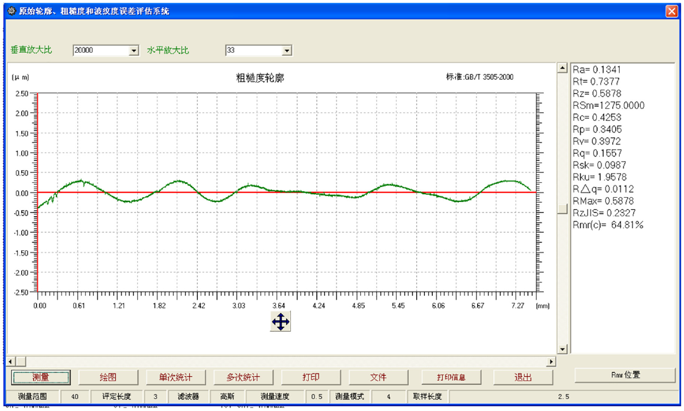
Surface profile of circular polishing trajectory of equidistant trajectory planning method.
Comparison results.

Conclusions
This paper uses the projection method to map the spatial polishing trajectory, analyzes the mapping relationship between the polishing trajectory and the projection trajectory, and calculates the mathematical relationship between the amount of material removal and the track spacing and overlap length of circular polishing. It also analyzes the influence of contact area change, geodesic radius of curvature and polishing posture on the material removal of the curved surface. For the lack of equal overlap ratio spiral lines, a concentric circle trajectory plan with a controllable removal amount is carried out. Based on the overlap length model of the curvature change, the polishing area, the trajectory residence time and the total material removal model are obtained to determine the processing efficiency. For flat and rotationally symmetrical aspherical workpieces, formulate corresponding polishing schemes. Take the rotationally symmetrical aspheric surface as an example, when R ≤ a, fixed-point polishing was used; when R > a, circular polishing with gradual track pitch was used. By analyzing the relationship between the material removal contour and the contour change of the overlapping part, this paper solves the linear function of the overlap length, calculate the total material removal, the material removal amount of each circular track and the residence time, and determine the processing efficiency.
Footnotes
Handling Editor: Chenhui Liang
Declaration of conflicting interests
The author(s) declared no potential conflicts of interest with respect to the research, authorship, and/or publication of this article.
Funding
The author(s) disclosed receipt of the following financial support for the research, authorship, and/or publication of this article: This research was funded by National Natural Science Foundation of China, grant number 51135006.