
Abstract
In the process of sublevel acidizing and fracturing, the non-uniform load on production casing is complex, and casing failure occurs frequently, which seriously affects the next step of production, stimulation, and underground safety of the oil and gas well. Aiming at the deformation and failure problem of perforated casing in ultra-deep horizontal wells, residual strength analysis and safety evaluation of directional perforated casing under sublevel acidizing and fracturing conditions were carried out. Due to the large scale difference between the underground formation and casing and the complex geometry of the model, an indirect coupled two-step method was proposed to determine the external load of casing first and then calculate its mechanical strength. By using this method, the stress level and distribution of perforated casing in in-situ stress field of X well are determined, and the safety factor of casing is analyzed. On this basis, considering the redistribution of in-situ stress field in the sublevel acidizing and hydraulic fracturing process, the stress situations on perforated casing under different in-situ stress differences are studied, and the measures to prevent casing failure are given. The proposed calculation method can provide references for casing selection and perforation process design of ultra-deep horizontal wells.
Keywords
Introduction
Hydraulic fracturing and acidification technologies have been widely used in ultra-deep oil and gas wells with complex downhole environments. Combined with the perforation completion process, the flow channel between the reservoir and the wellbore is fully opened, allowing oil and gas to flow from the reservoir into the wellbore, thus achieving the purpose of production increasement. However, in the process of multi-stage acidification and hydraulic fracturing, the working conditions of casing in the wellbore are complex, and perforation will destroy the overall strength of the casing and cause local stress concentration. Therefore, casing deformation and failure accidents occur frequently in the multi-stage acidification and fracturing operating conditions of ultra-deep horizontal wells, and the casing damage is serious. 1 Casing deformation is a serious threat to wellbore integrity, making it difficult to guarantee the safety of subsequent drilling, gas production, and stimulation, increasing the cost and difficulty of operation, shortening the life cycle of the wellbore, and reducing the stimulation effect.
In order to study the mechanism of casing deformation and failure in the process of multi-stage acidification and hydraulic fracturing, and give the prevention measures of casing failure in actual working condition, in recent years, a large number of experts and scholars have studied casing deformation in the process of acidification and fracturing of horizontal wells. In the process of multistage acidizing and fracturing, many factors in wellbore and formation change rapidly, and the load on the casing is complicated and changeable. Adams et al. 2 determined the cause of casing failure based on field data investigation, and established a comparison model of casing combined load and yield strength by considering casing air load, wellbore fluid buoyancy effect, piston effect, bending, corrosion, and temperature factors during fracturing. Lian et al. 3 established a finite element model of the formation including clustering perforation casing with effective stimulated reservoir volume for a shale gas horizontal well and found that the stress deficit of zero stress areas and tension stress areas occurred during the hydraulic fracturing process, which could cause the certain degree of deflection deformation radically and S-shape deformation axially. Lin et al. 4 investigated the effect of dynamic adjustment of rock mechanics properties on casing deformation during fracturing through the rock mechanics experiments and numerical simulations. Their research results show that the angle of a single crack and the crack number are affecting the strength of the rock, thus affecting the casing deformation. Yu et al.5,6 investigated the possibility of casing damage due to strong shear stress generated by asymmetric excitation. Overlapping stimulation zones at adjacent stages may exacerbate asymmetries in pore pressure distribution and resultant shear forces. Continuous re-distribution and re-orientation of stress field near the borehole are tracked during the development of the fracture network which reveals some pocket of tensile stresses along the casing which could cause the casing deformation. Zhang et al. 7 discussed the influence of the induced stress from the crack on casing, studied the loading situation near the wellbore by incorporating variation fracturing methods and operation parameters. They noticed that the casing deformation in shale gas wells mainly occurs near the heel of the horizontal section, shear failure is the main type and the initiation and expansion of crack can lead to the accumulation of non-uniform stress nearby the wellbore. Yu et al. 8 suggested that stress interference between two adjacent stages during multistage fracturing could exacerbate uneven loading on the casing string and lead to failure and established a coupled 3D reservoir-scale model with complex well trajectory and tie it to a single well scale model consisting of casing and the surrounding cement sheath. He found that perforating reduced casing strength, but that the reduction might not change further once the perforation diameter reached a certain value. Besides, Considering the high-density perforations can affect the overall strength of the casing, causing it to be damaged during fracturing, Guo et al. 9 established a 3D finite element model to ensure it. Dou et al. 10 measured and confirmed the stress concentration factor around the perforated hole through experimental and finite element analysis. The perforation holes are regarded as semi-elliptic surface cracks on the casing and the calculation formula of stress intensity factor and correction factor of perforation holes are derived. They found that the perforations significantly reduced casing collapsing strength. In another aspect, the cyclic load on casing during multistage fracturing is the main cause of casing fatigue failure. The casing under cycling loads are available to generate residual strain, and the accumulation of induced stresses from hydraulic fractures increases the maximum principal stress near the wellbore.11–13 Moreover, in acidizing fracturing conditions, activation and slip of faults caused by fluid entering the formation can also seriously affect casing integrity.14–23
At present, numerical simulation analysis is the main method of casing deformation and failure mechanism research. However, due to the large scale differences among the underground formation, casing, and perforation in ultra-deep horizontal wells, the finite element analysis model is complex, and it is difficult to mesh, and the results obtained by direct calculation are very inaccurate considering the fluid-structure coupling effect of formation pore pressure change and in-situ stress redistribution during the sublevel acidizing and hydraulic fracturing process. In order to improve and ensure the accuracy of calculation, an indirect coupling two-step method is proposed to calculate the stress level and distribution of perforated casing under the acidizing and fracturing condition of a certain well. A two-dimension casing-cement-formation finite element model was established to determine the non-uniform external load on casing during the acidizing and hydraulic fracturing process. On this basis, a three-dimensional segmental directional perforating model was established and the obtained load was applied to study the stress of different perforating casing sections under this condition and analyzed its safety.
Theoretical analysis of casing compressive strength
Collapsing strength analysis of casing subjected to non-uniform in-situ stress
The loading capacity of casing can be reduced by non-uniform in-situ stress, and the elastic plastic deformation of casing can also occur under small non-uniform in-situ stress, and the deformation amount is much larger than that under uniform in-situ stress. To make the casing produces plastic deformation, non-uniform in-situ stress is much smaller than uniform in-situ stress, in order to quantificat the casing collapsing strength reduction under non-uniform in-situ stress, the collapsing strength of casing under the non-uniform in-situ stress can be expressed as the mean value

If the external load of casing is irregularly and discretely distributed, then:

In the formula, n is the sum of [0, 2π] into n intervals.
According to the above two definitions, the collapsing strength
Theoretical analysis of the effect of perforation on casing collapsing strength
The compressive strength coefficient refers to the ratio of the compressive strength of the casing after perforation to the compressive strength of the casing without perforation. For casing without holes, casing thousands of meters underground belongs to plane strain elastic-plastic mechanics problem, and the model has axial symmetry. According to elastic mechanics theory, the structural formula of stress solution of the model is as follows:

Where, A, B, and C are arbitrary constants.
Its boundary conditions are

The solution of equation (4) can be obtained from the boundary condition (5)

According to equation (6), when the difference between

If the casing thickness is far less than the casing diameter (D/t ≥ 15), it can be considered that equation (7) is true. The stress of casing body can be considered as only

At this time, there is only one circumferential compressive stress
The negative sign in the formula indicates that the casing wall is under pressure.
According to the relationship between perforation diameter, casing thickness and casing diameter mentioned above, the inner wall of the casing can be expanded approximately. A single hole can be assumed as an orifice plate model. The structural formula of the stress solution can be obtained according to the theory of elasticity:

Where, A, B, C, and D are arbitrary constants.
Its boundary conditions are

The solution of equation (10) can be obtained from the boundary condition equation (11):

The equivalent stress value is calculated by the fourth strength theory

Substitute equation (8) into equation (9) to obtain

Thereinto

Where, r is the radius, mm; a is hole radius, mm; θ is the Angle with the horizontal forward direction.
When the inner wall of the casing is unfolded in a plane, the circumferential stress it is subjected to can be regarded as the plane unidirectional stress. For the plane unidirectional stress, the internal stress can be transformed into the external force q. In the numerical

The minus sign is pressure.
Substitute equation (16) for equation (13), then
If r and θ in equation (15) are determined, when

Thereinto

Where,
It can be seen that the theoretical formula can provide a way to solve the model, but the analytical method will ignore many factors that affect the actual calculation results, and it is difficult to calculate under special and complex conditions. Therefore, it is necessary to use the finite element method.
In the actual working conditions, the load on the casing is a dynamic process. However, in this study, we consider the worst working conditions in the acidizing and fracturing process of ultra-deep horizontal wells, where the casing is subjected to the maximum wellbore pressure and the worst non-uniform external load. At this point, if the safety factor of perforating casing material meets the safety conditions, the casing can also meet the safety requirements in other working conditions. Hence, we believe that the static load of casing under the worst conditions can be used as the condition for checking the safety factor of perforating casing in the process of acidizing fracturing.
Numerical modeling
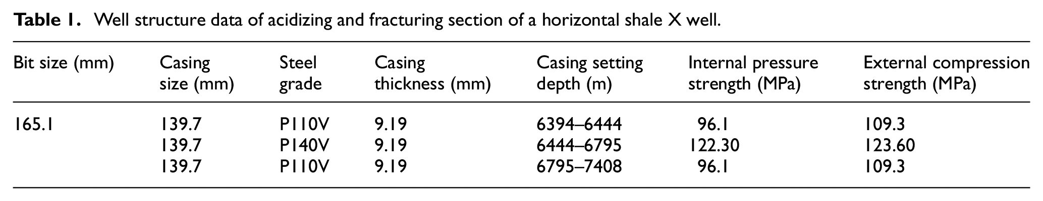
The production casing of the X well is 139.7 mm ×9.19 mm, and the steel grade is P110 and P140V. The specific parameters of the well structure are shown in Table 1. According to field logging and oil test data, the predicted temperature and pressure of the well are as follows: geothermal gradient 1.95°C/100 m, bottom hole temperature about 130.42°C. The pressure coefficient of the target formation is 1.113, and the bottom hole pressure is about 73.03 MPa.
Well structure data of acidizing and fracturing section of a horizontal shale X well.
Combined with the well structure parameters and temperature and pressure prediction results, an acidification and fracturing construction scheme can be designed for this well. The specific design scheme parameters are shown in Table 2, and corresponding wellhead pressure and displacement parameters of three stages of fracturing are given. Directional perforation was used to increase the contact area between the reservoir and the wellbore.
Sublevel acidizing and fracturing construction scheme design of X well.

Figure 1 shows the wellbore structure in the horizontal section and the loads on entities around the wellbore. In the vertical direction, the wellbore is subjected to vertical in-situ stress
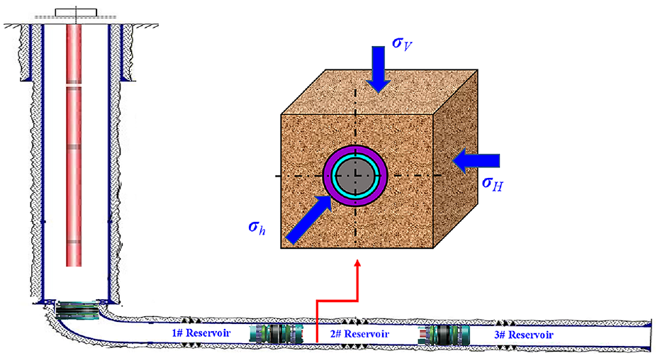
Load diagram of horizontal wellbore and entities around the borehole.
For this two-dimensional finite element model, the element type selected is PLANE82 plane strain element. The mesh is encrypted at the position of casing and cement sheath to ensure the accuracy of casing stress calculation. The final model formed 16,320 elements. The sparse director solver is used for the static analysis of 2D plane strain types.
The 2D finite element model of casing-cement-formation in horizontal acidizing and hydraulic fracturing section after simplification is shown in Figure 2 The contact coupling model used between casing and cement sheath and between cement sheath and formation. During the acidizing and hydraulic fracturing process,

Two-dimensional casing-cement-formation model diagram in horizontal section.
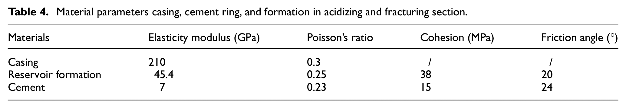
Table 3 shows the basic mechanical parameters of the mechanical model in the horizontal acidizing and fracturing section of the well, and Table 4 shows the material parameters of casing, cement, and formation material. Setting the mechanical load and material parameters of the model can reflect the stress on the casing during acidizing and fracturing process.
Basic mechanical parameters of the finite element model in horizontal acidizing and fracturing section.

Material parameters casing, cement ring, and formation in acidizing and fracturing section.
The perforating casing structure in the horizontal acidizing and fracturing section is asymmetric, so the model cannot be established by using the plane strain problem in Figure 2 Instead, a 3D model of casing finite element calculation must be established, as shown in Figure 3. The non-uniform in-situ stress on the outer wall of the casing needs to be calculated by the casing-cement-formation contact coupling model shown in Figure 2. The non-uniform in-situ stress is then applied to the outer wall of the perforated casing shown in Figure 3. The casing inner pressure in the process of acidizing fracturing is applied to the inner wall of casing, and the hydrostatic pressure is applied to the inner wall of perforation hole. The three reservoirs in the acidizing and fracturing section of the well were perforated with different azimuth angles. The perforating azimuth angles of 112°, 180°, and 217° were used in reservoirs #1 to #3 respectively. The finite element model in Figure 3 also simulated the perforating azimuth angles of different reservoirs. Among them, the SDP39HMX25-2 type perforating bullet is selected, and the perforating diameter is 9.5 mm.

Horizontal acidizing and fracturing section diagram and finite element model of perforating casing and in-situ stress and internal pressure.
For this 3D finite element model, the element type selected is SOLID185 3D stress element. The mesh is encrypted in and around perforation holes to ensure the accuracy of perforation stress calculation. The final model formed 44,260 units. The sparse director solver is used for the static analysis of 3D stress types.
The Drucker-Prager failure strength criterion (DP criterion) was adopted in the finite element modeling and analysis. The DP criterion is an extension of von Mises fourth strength criterion. DP strength criterion is a conical plane in the principal stress space due to the existence of internal friction of rock, and the specific form is as follows:

Where
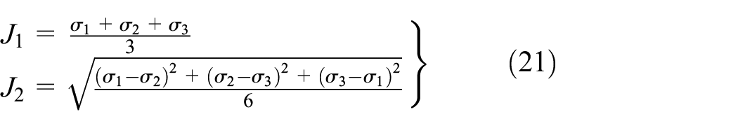
In equation (20),
In numerical calculation,
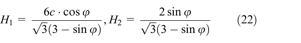

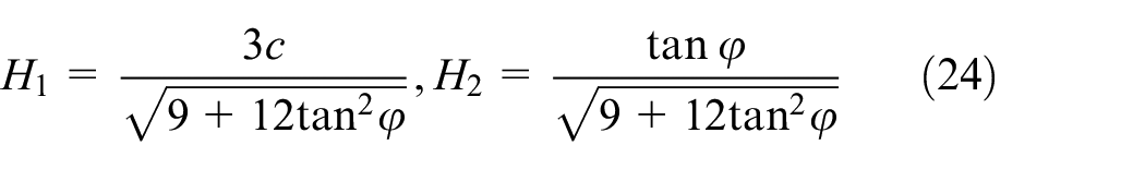
Where, c is the cohesion of materials, MPa;
In order to reflect the dilatancy caused by rock shear, the DP strength criterion considers the influence of intermediate stress and hydrostatic pressure on the yield process. DP criterion is also widely used to simulate the plastic properties of rock materials. In this study, the DP criterion was used to characterize the plastic failure characteristics of the formation rock and cement ring, while the uniaxial tensile stress-strain function of the casing steel was used directly to characterize the plastic response of the casing material. The same material property Settings were used in subsequent 2D and 3D models.
The von Mises failure criterion was used to determine whether the casing steel had entered the yield stage, and the expression was as follows:

When
The safety factor could be calculated by the ratio of minimum yield stress of casing material to the maximum von Mises stress:
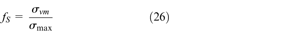
Where,
When the safety factor is greater than or equal to 1, it indicates that the material does not yield and is in a safe state. Otherwise, it indicates that the material will yield, and there may be safety risks.
Simulation results and discussion
Casing external load calculation
According to the established calculation method, the external load of casing in horizontal section under acidizing fracturing condition should be calculated first. Therefore, based on the 2D casing-cement-formation plane-strain finite element model in Figure 2, the non-uniform load transmitted from the formation to the casing wall and the Mises stress distribution in the casing were calculated during 85 MPa acidizing fracturing, as shown in Figure 4. It can be seen that the maximum Mises stress 334 MPa occurred at 90° and 270° of the casing medial wall, which was consistent with the direction of vertical in-situ stress. This is because the casing is extruded by the non-uniform in-situ stress from the formation, the vertical in-situ stress is larger than the horizontal maximum in-situ stress, and in the acidizing fracturing operation, the casing is subjected to a large wellbore pressure. The joint action of several loads results in the stress concentration phenomenon along the vertical direction of in-situ stress in the casing medial wall.

Mises stress distribution contour of casing in acidizing and fracturing section.
It can be seen from the Mises stress cloud distribution of casing in Figure 4 that the maximum stress of 333 MPa in the casing is much lower than the yield stress of 758.6 and 965.5 MPa in P110 and P140V casing. The outer wall of the casing from 0° to 90° in Figure 4 was selected as the path, and the contact pressure on the outer wall of the casing was extracted along this path, as shown in Figure 5. It can be seen that the maximum contact pressure on the outer wall of the casing appears at 90° of the path, and the maximum contact pressure is 123.4 MPa.

Variation of casing wall contact pressure along0°–90° path.
The expression of non-uniform external load on casing wall from formation can be fitted from the curve of the contact pressure of casing wall changes along 0°–90° path in Figure 5:

The non-uniform external load of equation (27) can be directly applied to the outer wall of 3D perforating casing shown in Figure 3, so that the stress level and distribution in perforating casing can be simulated.
Strength calculation of directional perforating casing in acidizing and fracturing process
In order to calculate and research the stress level and distribution of orientation perforating casing in section acidizing and fracturing process, the non-uniform contact pressure generated by the extrusion of in-situ stress is applied to the outer wall of the three-dimensional casing model in the perforating section, that is, p in equation (27) of the contact pressure calculated by the two-dimensional plane model. As shown in Figure 6, when the wellhead pressure is 85 MPa, the inner wall of the casing applies the wellbore pressure Pin = 153 MPa.
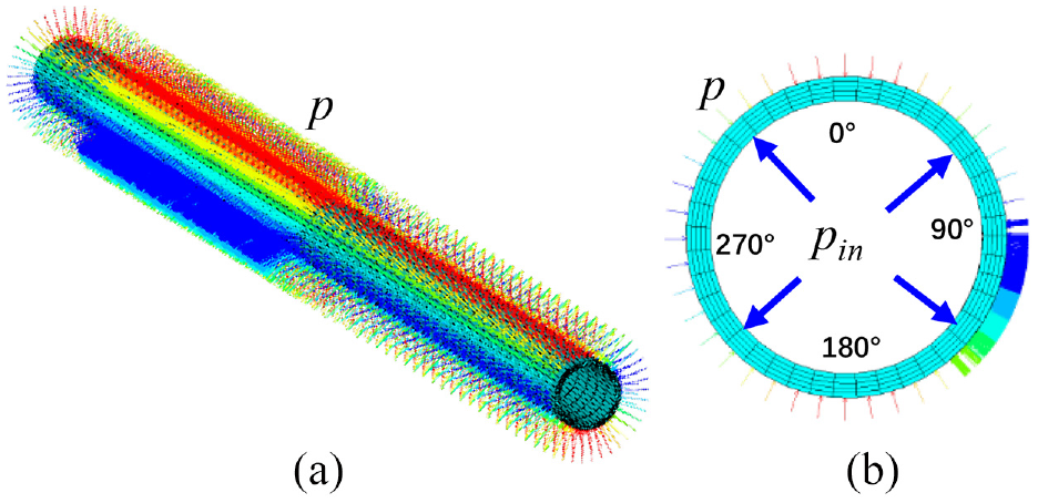
Finite element model loading of perforated casing in acidizing and fracturing section: (a) the overall view and (b) axial view.
According to the finite element model in Figure 6, the calculation results are shown in Figures 7 and 8. It can be seen from Figure 7 that the maximum stress in the perforated casing is 612 MPa, occurring in the inner wall of the casing at the perforated section, while the maximum stress in the unperforated casing is 329 MPa, occurring in the 0° and 180° positions of the inner wall of the casing.

Mises stress distribution contour of the casing in acidizing and fracturing section: (a) full model section and (b) axial view of non-perforated section.
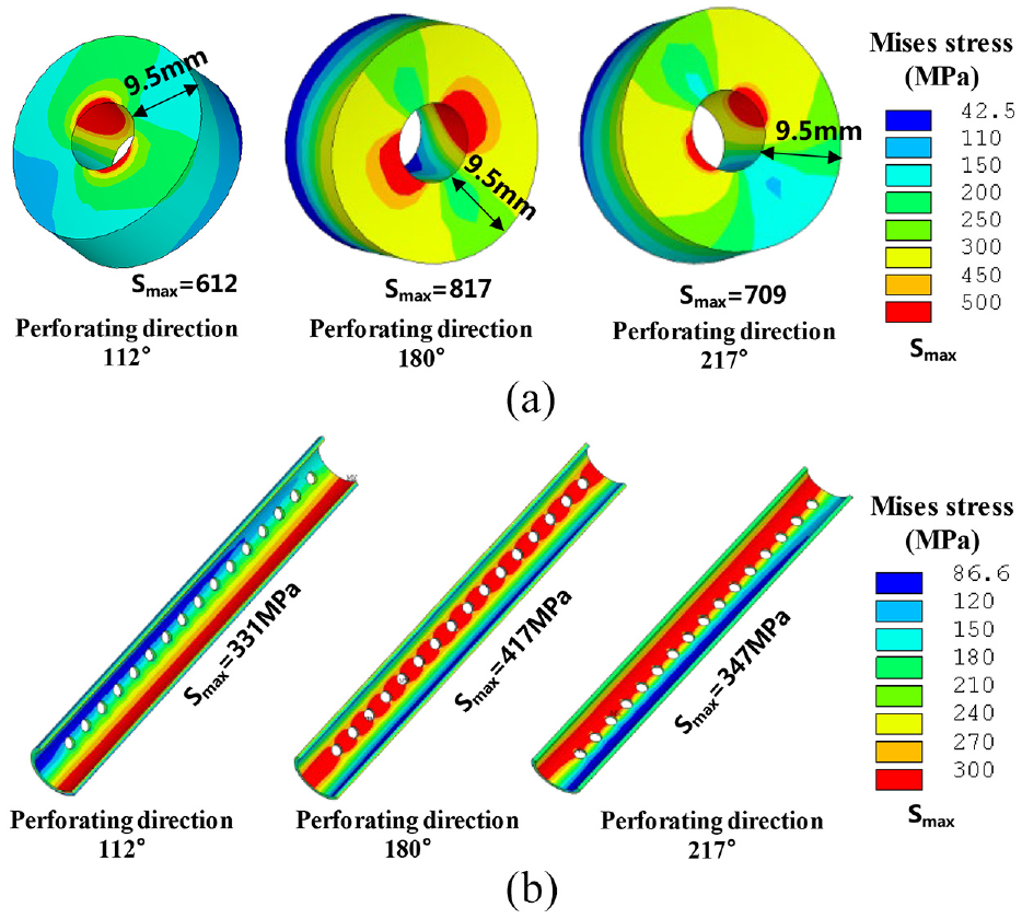
Mises stress distribution contour of perforated casing in acidizing and fracturing operation: (a) the stress distribution contour within 9.5 mm from perforation hole and (b) the stress distribution contour of perforated casing section after removing the 9.5 mm range around the hole.
As can be seen from Figure 8(a)), in each perforating orientation, the maximum stress occurs in a small range of the inner wall of the perforating hole, and a small part extends to a small range of the inner wall of the casing. The red area with large stress does not completely pass through the wall thickness of the hole, which belongs to the stress concentration in a local area. In the 1# and 3# reservoirs, the casing material was P110 steel grade and perforated at 112° and 217° orientations. The minimum yield stress of the P110 casing is 758.6 MPa. When the perforating orientation is 112° and 217°, the maximum stress is 612 MPa and 709 MPa respectively. In spite of the stress concentration, the maximum stress is less than the minimum yield stress of the casing, so the casing will not yield. In the 2# reservoir, the casing material is P140V steel grade, and the perforating orientation is 180°. The maximum value of stress concentration around the perforation hole is 817 MPa, but its location is only a small part of the inner wall of the perforation, and it does not exceed the minimum yield stress of P140V casing 965.5 MPa. Moreover, the acidizing fracturing process is relatively short, after that, the high stress in the casing will be released soon with the decrease of the pressure in the wellbore. It can be seen from Figure 8(b)) that under the three perforating orientations, the maximum stress was less than 417 MPa after removing the stress in the 9.5 mm range around the hole. Therefore, the mean values of Mises stress were all lower than the minimum yield stress of P110 in the three perforating directions. Therefore, the P110 casing can meet its mechanical strength requirements, and the P140V casing can better meet the mechanical strength requirements of the well.
It can be seen that the maximum stress concentration of 817 MPa around the hole exceeded the minimum yield stress of 758.6 MPa at the perforating orientations of 180°. According to the comparison of directional perforation orientation, the direction of non-uniform load on the casing and the direction of in-situ stress, it is found that the 180° perforation orientation is consistent with the maximum direction of non-uniform load on casing shown in Figures 4 and 5, as well as with the direction of vertical in-situ stress. It can be concluded that when the orientation of directional perforation is close to the position of the maximum non-uniform load of the casing, the stress concentration caused by perforation is more obvious, and the stress value here may exceed the minimum yield stress of casing material and enter into yield. Therefore, when choosing the orientation of directional perforation, the position of maximum non-uniform load on the casing should be considered as far as possible to ensure the overall safety of the casing. Furthermore, the maximum Mises stress at 217° was 709 MPa, which was close to the minimum yield strength of the P110 steel casing. In actual working conditions, multi-stage hydraulic fracturing may cause the casing to be subjected to cyclic loading, and the perforation location may cause fatigue deformation at the end, affecting the integrity of the casing.
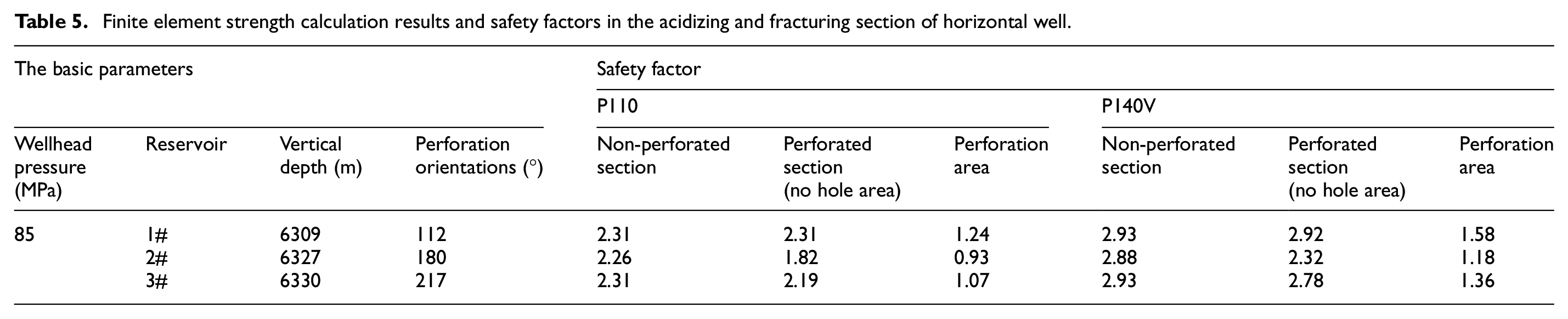
Based on the simulation results of casing stress level and stress distribution, the casing safety factor of horizontal well under the acidizing and fracturing condition with 85 MPa wellhead pressure can be calculated, as shown in Table 5. It can be seen from the table that the safety factor is greater than 1 except that the perforating orientation is 180° and the wellhead pressure is 85 MPa, which is 0.93. If some stress concentration in the hole is excluded, the other safety factors are above 1.94, that is, all the casing with steel grade above P110 meets the requirements of acidizing and fracturing.
Finite element strength calculation results and safety factors in the acidizing and fracturing section of horizontal well.
Influence of in-situ stress change caused by acidizing and fracturing
In the above calculation, the data provided by logging and oil test data were used to apply the casing model load in the horizontal section, that is, the vertical in-situ stress is 166 MPa calculated from overburden pressure, the horizontal maximum in-situ stress is 118 MPa, and the formation pore pressure is 70 MPa calculated from formation depth and formation pore pressure coefficient. However, in the process of acidizing fracturing, the formation of an asymmetric fracture network may cause the non-uniform change of external extrusion load on the casing. This is because after the acid and fracturing fluid enter the formation, the formation pore pressure changes, the formation rock structure changes, will cause the redistribution of in-situ stress field, the ground stress difference of the casing changes accordingly. Therefore, the influence of in-situ stress difference change on the strength of directional perforating casing under acidizing and fracturing condition can be studied by controlling the in-situ stress difference in model load.
The casing-cement-formation plane strain model shown in Figure 2 can be used to calculate the stress level and distribution of non-perforated casing in the horizontal section under the action of different in-situ stress differences, and the corresponding non-uniform contact pressure of casing outer wall is extracted for subsequent calculation of casing stress in perforated section. In the in-situ stress field, the difference suffered by the horizontal casing is 48 MPa, and the size of the in-situ stress difference controlled is 10, 30, 50, 70, and 90 MPa. Among them, the vertical in-situ stress is mainly affected by the overburden pressure and basically does not change, so the maximum horizontal in-situ stress is adjusted for 156, 136, 116, 96, and 76 MPa respectively. The calculated maximum Mises stress curve of non-perforated casing was shown in Figure 9. It can be seen that the maximum Mises stress increases with the increase of the in-situ stress difference, and the linear relationship is presented. This shows that the heterogeneity of in-situ stress has a great influence on the casing stress level. In practical engineering, a higher steel grade or larger wall thickness casing should be used in the reservoir with a larger in-situ stress difference.
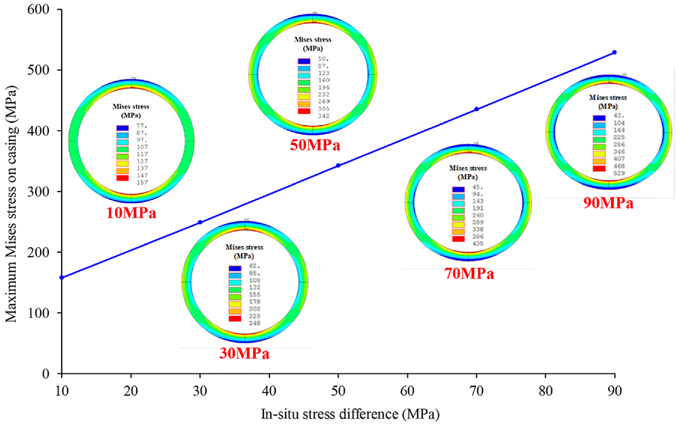
Relationship between maximum Mises stress and stress difference of casing.
The outer wall contact pressure of casing under different in-situ stress differences was taken as the non-uniform external load of casing in perforating section, as shown in Figure 10. It can be seen that the increase of the in-situ stress difference is realized by reducing the horizontal maximum in-situ stress. Therefore, with the increase of the in-situ stress difference, the contact pressure level on the casing wall gradually decreases, while the non-uniformity of the contact pressure on the casing wall path significantly increases. According to the method in Figure 5, the contact pressure curve formula on the outer wall path of casing under different in-situ stress differences was fitted, as shown in Figure 11, and loaded onto the 3D perforated casing model.

Annular curve of contact pressure on casing wall.

Contact pressure of casing wall under different in-situ stress difference along 0°–90° path.
Through the simulation calculation of 3D perforating casing finite element model, under the effect of in-situ stress differences, the corresponding Mises stress in the vicinity of perforation holes in three perforating sections is shown in Figure 12. It can be seen that with the increase of in-situ stress difference, although the load level on the casing wall decreases, the non-uniformity is greater, and the stress concentration at each perforation location is more obvious.

Mises stress at 112° casing perforation range at different in-situ stress differences.
It can be seen from Figure 12 that the maximum stress concentration of casing in three perforating directions near the perforation holes increases with the increase of non-uniformity of external load, and eventually exceeds the minimum yield stress of P110 steel-grade casing material, which may lead to yield deformation failure. Therefore, in practical engineering applications, higher steel grade material or higher wall thickness should be selected for casing in the case of large or possibly changing in-situ stress differences. When the perforating orientation is 180°, the stress value of perforating hole position increases rapidly first and then decreases slowly with the non-uniform increase of external load. This is because although the non-uniformity of external load increases, its level decreases. In general, when the orientation of perforation is consistent with the direction of maximum in-situ stress, the stress value near the perforation hole is greater. In addition, as shown in Figure 13, when the perforation orientation is 180°, the increased non-uniformity of external load significantly increases the stress concentration range around the perforation hole, and increases the possibility of material yield.

Mises stress at 180° casing perforation range at different in-situ stress differences.
The Mises stress distribution could be obtained by taking the perforation circumference on the inner surface of the casing as the path, as shown in Figure 14. It can be seen that the greater the difference of in-situ stress, that is, the stronger the non-uniformity of the load on the perforated casing, the larger the stress concentration range around the perforated hole. A wide range of stress concentration is more likely to cause the casing material to yield, and fatigue failure is more likely to occur under the action of cyclic loads in multistage acidizing and hydraulic fracturing.

Circle Mises stress distribution of perforated holes on casing wall.
Conclusion
Using the indirect coupling two-step method, the mechanical strength and safety of orientational perforating casing under the condition of sublevel acidification and fracturing of ultra-deep horizontal wells are analyzed, and the following conclusions can be drawn:
The maximum stress at the area outside the vicinity of the perforation holes of the three perforating orientations was not more than 417 MPa. The results showed that the average Mises stress on casing sections was lower than the minimum yield stress of P110 at 758.6 MPa, indicating that perforation did not reduce the overall casing strength in origin in-situ stress field, during the acidizing and fracturing process.
In acidizing and hydraulic fracturing conditions, the stress concentration phenomenon occurs near the perforation hole. When the orientation of perforation is close to the position where the maximum non-uniform load on casing, the stress concentration phenomenon caused by the perforation holes is more obvious, and the stress value may exceed the minimum yield stress of casing material and enter into yield. Therefore, when choosing the orientation of perforation, it is necessary to deviate from the direction with the largest non-uniform load on the casing as far as possible, or choose a higher steel grade of casing material or increase the thickness of the casing wall to ensure the overall safety of casing.
The maximum Mises stress occurred at the inner wall of the holes under different perforating directions. In the in-situ stress field, the area with high stress around the casing perforation hole does not pass through the casing wall thickness, which is local stress concentration and basically does not affect the overall casing strength. According to the calculation results of the safety factor, the safety factor is greater than 1 except 0.93 when the wellhead pressure is 85 MPa in 180° perforating orientation. If the stress concentration areas in the hole are excluded, the other safety factors are above 1.94, that is, the P110 steel casing meets the fracturing requirements. If the P140V steel casing is selected, it can better meet the mechanical strength requirements of the well.
The change of in-situ stress difference has a significant influence on the casing stress level and the non-uniformity of external load. The greater the difference of in-situ stress, the higher the stress level on the casing, the stronger the non-uniformity of external load on the casing.
The stronger the non-uniformity of the external load on the casing, the higher the stress level in the vicinity of the casing perforation holes, and the larger the range of stress concentration. A wide range of stress concentration is more likely to cause the casing material to yield, and fatigue failure is more likely to occur under the action of cyclic loads in multistage acidizing and hydraulic fracturing.
Footnotes
Handling Editor: Chenhui Liang
Declaration of conflicting interests
The author(s) declared no potential conflicts of interest with respect to the research, authorship, and/or publication of this article.
Funding
The author(s) disclosed receipt of the following financial support for the research, authorship, and/or publication of this article: The authors are grateful to the support from the National Natural Science Foundation of China (No. 51974271 and No. U19A209).