
Abstract
In this paper, the jet control effect of air vehicle is studied, and a new multi parameter coupling unsteady test technique is established, which can ensure that the test model is consistent with the real air vehicle, and the jet is carried out under the condition of complete freedom and no support constraints, so that the wind tunnel test can better simulate the jet control effect of real air vehicle. The new technique overcomes the shortcoming that the previous jet test can only carry out unsteady flow field or unsteady aerodynamic force research, and can ensure that in the whole process of jet flow, the interference flow field at the nozzle, the aerodynamic force of the air vehicle, especially the movement of the air vehicle, are coupled with each other all the time, so as to achieve the same effect as the real air vehicle. The establishment of the new technique overcomes many problems, including the total length of the model is 167 mm, no support for the model, storage of small volume/high-pressure gas in free state, on-time unlocking of sealed gas source in free state of the model, and connection of gas source and nozzle in the model. The test results show that when no jet, the revolution body is head up, which affected by the cavity shock wave. When jet on, the jet force continues to act on the revolution body, resulting in the revolution body lowering its head until it diverges. The new technique can achieve more advanced technical indicators, including: ensuring jet Mach number >1; Ensure that the static pressure ratio of the jet is more than 10 (the static pressure ratio can be greater at hypersonic speed). After the establishment of the new technique, the supersonic wind tunnel test is carried out, and the ideal test results are obtained, which shows that the new technique is reliable.
Keywords
Introduction
High maneuverability and fast response are important characteristics of advanced air vehicle. The traditional pneumatic rudder as a single actuator is not competent.1,2 Jet control technique is an important means of air vehicle flight control. It has the advantages of simple structure, no influence on aerodynamic shape, short response time and no influence from external flow. Moreover, the adverse effect of local aerodynamic heating of aircraft under hypersonic condition can be effectively avoided by jet control. Compared with the control rudder, the air vehicle with jet as reaction control system can maintain rapid response and high maneuverability even in low-speed or low-density areas. Jet control is one of the key techniques in aerodynamic design of advanced air vehicle.3,4
Researchers have carried out a lot of research work on jet control. Spaid and Zukoski 5 studied the interaction between jet and different flow conditions, and studied the main parameters of jet interaction flow field. Aso et al. 6 experimentally studied the effects of jet pressure ratio and jet width on jet interaction. Won et al. 7 conducted numerical research on the basis of the experiments. Huh and Lee 8 carried out numerical analysis of supersonic cross flow transverse jet of a flat plate and on a generic missile. The numerical results are validated with wind tunnel data. The flow structure due to the jet interaction with the supersonic freestream is examined in terms of the vortex structure. Luo et al. 9 used Fourier transform and high-speed schlieren image processing methods to study the control effect of high-frequency plasma synthetic jet on low-frequency instability of shock boundary layer interaction. Guo et al. 10 designed a reverse jet of hypersonic bluff body, which significantly changed the external flow and produced considerable aerodynamic drag reduction. Wallis 11 conducted a jet interaction test on a flat plate in a supersonic wind tunnel, observed the shock structure and pressure-sensitive coating with schlieren image, and obtained the surface pressure diagram. Viti et al. 12 conducted Computational fluid dynamics (CFD) analysis of Wallis wind tunnel test and captured the detailed physical phenomena of jet interaction. Stahl et al. 13 conducted an experiment on the interaction between air jet and hot gas jet on a general aircraft model. Michael 14 studied the control authority of Attitude Control Motors (ACMs) for pitch control of an early candidate design of the Orion Launch Abort Vehicle (LAV). Investigations of Jet Interaction (JI) showed that adverse JI occurs at positive angles-of-attack when the ACM jets screen the LAV tower from the oncoming flow. Beresh et al. 15 studied the interaction created by a supersonic axisymmetric jet exhausting transversely from a flat plate into a transonic crossflow. Data have been acquired in the crossplane of the interaction at a single station in the far field. Sufficient data were acquired to determine all six unique components of the turbulent stress tensor, providing the mean spatial character of the anisotropic turbulence. Kawai 16 obtained insights into the physics of the jet mixing. Jet mixing calculations where the upstream boundary layer is fully turbulent are also compared with corresponding calculations with a nominally laminar boundary layer. Statistics obtained by the LES with turbulent crossflow showed good agreement with the experiment and a series of mesh refinement study showed reasonable grid convergence in the predicted mean and fluctuation flow quantities. Kang et al. 17 conducted numerical and experimental analysis on the jet interaction of supersonic aircraft and obtained aerodynamic database. Kwak et al. 18 introduced the influence of turbulence model on flow separation using wing structure. Christie 19 compared the influence of turbulence model on jet interaction flow.
To sum up, researchers have carried out a large number of extensive wind tunnel tests and numerical simulation for jet problems, accumulated rich research experience, and played a guiding role in air vehicle design. However, it should be noted that when the real air vehicle jet, the interference flow field at the nozzle, the aerodynamic force received by the air vehicle, and the air vehicle motion exist at the same time, and the three are coupled with each other. The previous research methods are mostly limited to the unsteady flow field or aerodynamic unsteady research, and the research involving the motion caused by jet is very rare. The purpose of jet flow is to make the air vehicle move, and the motion of the air vehicle will inevitably lead to unsteady changes of flow field and aerodynamic force. This change in turn will lead to further movement of the air vehicle. If we want to deeply study the mechanism of jet influence on air vehicle motion, we must study the flow field, aerodynamic force and motion together. In the existing public literature, there is no research method that can combine the unsteady coupling characteristics of jet flow field, aerodynamics and motion, and this research may still be in the blank stage. This will lead to the existing research results are not very sufficient, and there is a certain gap with the effect of real air vehicle jet.
Wind tunnel free flight test technique is a common research method to study the unsteady characteristics of air vehicle. It is different from other steady (force measurement after model support) and quasi steady test methods (capture trajectory simulation—CTS). It has the unique advantage of no support interference. The test uses high-speed photography to shoot the model through the observation window, and the curve of the six degree of freedom parameters of the air vehicle model with time can be obtained. In the later stage, the dynamic aerodynamic parameters of the air vehicle can be obtained through data processing. In recent years, Xue et al.20,21 have greatly improved and improved the previous wind tunnel free flight test technique and test theory, which not only expands the research scope of wind tunnel free flight test, but also ensures the accuracy and accuracy of wind tunnel free flight test. Meanwhile, Xue et al.22–25 also carried out exploratory research on jet characteristics.
Model free flight wind tunnel test technique and traditional jet control test methods have their own advantages. If the two can be combined to establish a new test technique and use the wind tunnel free flight test method to study the unsteady coupling characteristics in the jet process of air vehicle, it will better show the action process of jet and find the action principle of jet. The establishment of this experimental technique will be the focus of this paper.
Free flight wind tunnel test with jet control
Capability requirements for new techniques
Aiming at the problem of jet attitude control of air vehicle, this paper releases the six degrees of freedom of the model and establishes the unsteady test technique with jet control. The new test technique can reflect the specific impact of jet on air vehicle motion, and can also be used to predict the effect of jet on real air vehicle. The real air vehicle shape and nozzle position are diverse. In order to make this study representative, the air vehicle adopts the revolution body shape, and the nozzle is set in the vertical direction of the revolution body head and perpendicular to the surface of the revolution body. Therefore, the jet force mainly causes the pitching motion of the revolution body.
The appropriate wind tunnel shall be selected before the test design. Considering the difficulty in the initial stage of the establishment of new technique, the 1.2 m supersonic wind tunnel FD12 wind tunnel with larger size is selected. The Mach number of FD12 wind tunnel is representative, which can verify the feasibility of this test technique. At the same time, the experimental technique is universal. If the supersonic wind tunnel is feasible, it can also be used in the hypersonic wind tunnel. The Mach number of the wind tunnel is taken as M = 0.6. Carry out jet and closed jet wind tunnel tests, and obtain different test data in various states. Test process: after the wind tunnel flow field is stable, the free flying model is launched into the flow field, the unlocking device is connected with the compressed gas cylinder and conduit, and the gas in the gas cylinder is ejected at high speed from the nozzle. The attitude angle of the model is photographed by high-speed photography, and the image of the attitude angle changing with time and the control effect of jet are obtained.
The new technique needs to combine the wind tunnel free flight test and the conventional jet wind tunnel test, so the technical indexes of the new technique need to be representative. Item 1: jet velocity. The new technique is aimed at high-speed flow field, so the jet velocity must be compressible or even supersonic. The technical index of M ≥ 1.0 is very representative. However, it is very difficult to achieve this goal, and it is also the biggest difficulty to establish this experimental technique. Item 2: the jet static pressure ratio is an important parameter in jet research, which also needs to be examined here. The third item has been introduced in the introduction. It is to study the jet by unsteady test method, which is also a major feature of this experimental technique. After establishing the above research capability, it is necessary to verify the established new test technique, that is, the fourth index. Specific indicators and verification methods are as in Table 1.
Technical indexes and verification methods of free flight wind tunnel test with jet control.

In addition, another difficult problem in this paper is the model design. The free flight test models are relatively small, and the length is generally about 200 mm. All mechanisms required for the test, including small volume high-pressure air storage tank and unlocking mechanism, need to be installed inside the model, which increases the difficulty of design and processing. The model design is to install the compressed gas cylinder and cylinder unlocking device inside the model. The cylinder unlocking device and the nozzle are connected through the hose, and the nozzle is not limited by the position. It can be set at any position of the model. When the jet test is required, the unlocking trigger mechanism can connect the air source.
Small volume, high pressure gas storage, and unlocking
This test technique requires the model to jet in a completely free state. Therefore, the air source cannot be introduced into the model by using the vent pipe like the previous jet test, but the high-pressure gas and the model need to be designed as a whole. This paper uses the compressed gas cylinder to solve this problem. The compressed gas cylinder is designed as a part of the model and fixedly connected with the model, so as to solve the problem of jet gas source of free flying model. To solve this problem, the optimized and improved gas source is specially designed in this study, as shown in Figure 1, with a length of about 110 mm. The length of valve about 45 mm, the length of compressed gas cylinder about 70 mm. The diameter of valve about 16 mm, the diameter of compressed gas cylinder about 14 mm. The two are fixed by threads. In this test, the compressed gas cylinder can be filled with 8 g of carbon dioxide gas. As the gas cylinder wall is made of alloy steel, it can withstand large external pressure, and its ability to store gas is basically not affected by external pressure.

Improved small volume high-pressure gas storage bottle, with a length of about 110 mm.
In addition, the problem of on-time unlocking of high-pressure gas needs to be solved. Due to the high gas pressure in the compressed gas cylinder, the air introduction device must be triggered quickly and have good sealing, which can prevent the leakage of high-pressure gas. The use of spring striker and pull-out pin can ensure that the model can trigger the jet mechanism when it is completely free, and solve the trigger problem of the mechanism when the model is free, as shown in the black part of Figure 1.
Connection mode between air reservoir and nozzle
The nozzle of real air vehicle may be set at any position. In order to ensure the universality of this test technique, it is also necessary to ensure that the nozzle of this test technique can be set at any position. When the long hose is used for air injection, the pipe will be pulled out due to the principle of force and reaction force. The fixed block can ensure the fixed position of the nozzle. So as to ensure that the nozzle can be set at any position of the model.
Model design combined with new experimental technique
Figure 2 shows the internal structure of the designed test model. Fix the valve and high-pressure gas cylinder shown in Figure 1 inside the model, and use pipes to lead the high-pressure gas to the air outlet. At the same time, when jet is required, use the pull pin to unlock and trigger. At the same time, the design of the model also needs to ensure that the center of mass and inertia of the model are similar to those of the real air vehicle. In order to ensure that the airflow at the outlet of nozzles can reach supersonic velocity, nozzles adopt the design of outlet expansion, that is, the internal area of nozzles is small, the external surface outlet area is large, and the cone angle is 10 degrees. The pressure of the spring before unlocking is about 20 n, which can ensure that the unlocking function can be triggered and the required pressure can be ensured. At the same time, it is necessary to ensure that the strength of the spring striper is not damaged.

The internal structure of the designed test model.
Test preparation
Nozzle velocity measurement
As shown in Figure 3, fix the model on the test bench with a fixture, fill the nozzle with particles, and use particle image velocimetry (PIV) technique to measure the velocity of the model nozzle air flow when using different pressure cylinders. The results are as follows.

High speed photography of nozzle flow field.
It can be seen from Figure 4 that when the total pressure in the high-pressure cylinder is greater than 2.0 MPa, the velocity of the outlet gas flow can reach supersonic velocity, which is satisfied with Article one of the technical indexes. y is the jet vertical influence distance, x is the jet horizontal influence distance.
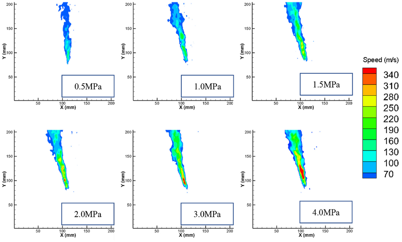
Nozzle velocity at different pressures of gas cylinders.
Test before wind tunnel test
According to the results of nozzle speed calibration, a gas cylinder with a total pressure of 4.0 Mpa is selected for the test. At the same time, the wind tunnel test model is processed. The processed wind tunnel test model is shown in Figure 5. The length of the model is 167 mm, meeting Article 2 of the technical index.

Test model, 167 mm.
As we all know, during the wind tunnel test, the flow pressure is large and there is strong turbulence. In order to avoid the impact damage of turbulence on the test device and model when the wind tunnel is started, the test model and device are specially installed in a cavity. The cavity protection model will not be damaged by turbulence when the wind tunnel is started, as shown in Figure 6. The length of cavity L = 200 mm, the width of cavity W = 80 mm, the height of cavity H = 60 mm.
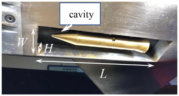
Installation diagram of test model.
In this test, high-speed photography is used for shooting, the shooting frequency is 2000 Hz, and auxiliary light source is used for light supplement. Photron’s SA5 color high-speed camera is used in this test. The lens is Nikon 80–200 mm focal length lens, and the aperture value used in the test is 4.0. The purpose of the test is to ensure the feasibility of the jet free flight test technique. Compared with the real wind tunnel test, it only lacks the external flow field. Two tests were carried out, jet on and jet off.
As can be seen from Figure 7, when the model is free at 4.0 Mpa, the jet can turn the model over. As can be seen from the Figure 8, the model lowers its head slowly when there is no jet.

Test results of model jet test technique under the condition of total pressure of 4.0 Mpa and no incoming flow.

No jet test results without incoming flow.
Through the above two tests without wind, the feasibility of the newly established test technique is verified, which can ensure that the wind tunnel test model can carry out jet test under completely free conditions, meet the design requirements, and can carry out wind tunnel test. At the same time, it also reflects the characteristics of jet changing the attitude of the model.
Wind tunnel test verification
FD12 wind tunnel is a subsonic, transonic and supersonic three speed wind tunnel of China Academy of Aerospace Aerodynamics, with Mach number range of 0.3–4.0, Mach number adjustment accuracy of 0.004 and test section size of 1.2 m × 1.2 m × 3.8 m. At transonic speed, the axial turbulence of FD12 wind tunnel is about 1.5%, and the vertical turbulence of FD12 wind tunnel is about 1.1%. The static pressure of FD12 wind tunnel is 85,833.6 Pa when M = 0.6. The nozzle adopts conical expansion form, which can ensure that the jet reaches supersonic velocity. The total pressure of the high-pressure cylinder is 4.0 MPa, and the measured Mach number at the nozzle is 1.5. It can be obtained that the static pressure at the nozzle is 1.090e06Pa at Mach 1.5. Therefore, it can be calculated that the ratio of static pressure at the nozzle to static pressure from the wind tunnel is 1.090e06/85,833.6 = 12.69, which is greater than 10 of the index requirements, and the third requirement of the technical index is completed. Figure 9 shows the scene picture of the wind tunnel test model installed in this test.
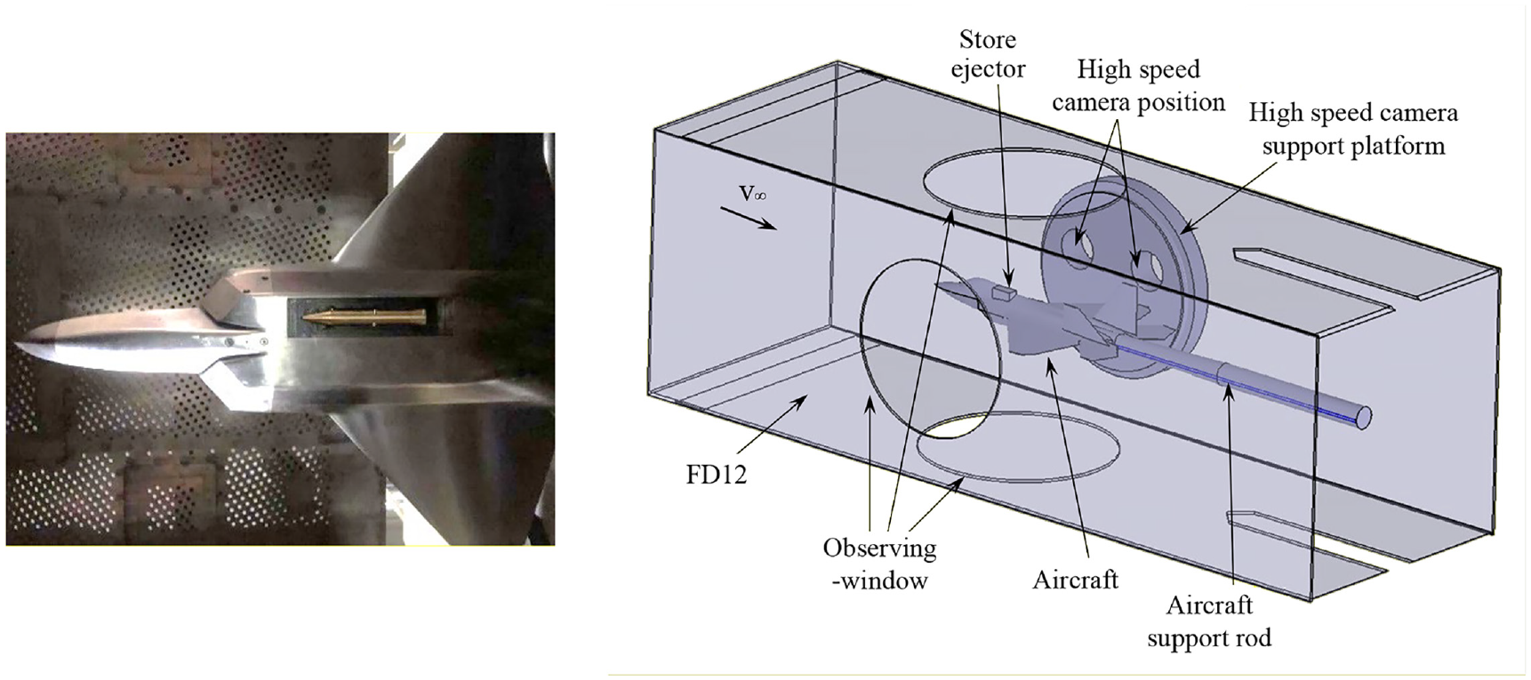
Installation diagram of wind tunnel test model.
The Figure 10 shows the attitude sequence diagram of the revolution body at Mach 0.6 and no jet.

Change of flight attitude of air vehicle without jet and M = 0.6.
During the no jet test, it was found that the image was too bright. In order to better show the jet characteristics, the shooting background was dimmed by placing a layer of paper on the observation window. The Figure 11 show the attitude sequence diagram of the revolution body with Mach 0.6 and jet.

Change of the revolution body flight attitude with jet and, M = 0.6.
Figure 12 is an enlarged view of the flow at the nozzle when t = 24 ms.

Enlarged view of the air flow at the nozzle at t = 24 ms, M = 0.6.
At the same time, we also carried out the test with shock wave, M = 1.5, as shown in Figure 13. The test M = 0.6/1.5 and the wind tunnel test sequence diagram have completed the requirements of items 4 and 5 of the technical indexes. Therefore, all technical indexes of this test technique have been completed.

Shock wave characteristics of the revolution body head with or without jet, M = 1.5.
The details of whether there is jet at the head of the revolution body are shown in Figures 12 and 13. It can be seen from the comparison figure that the jet at the head caused an obvious shock wave and changed the attitude of the revolution body, indicating that the jet caused the change of force and flight attitude of the revolution body.
It can be seen from the wind tunnel test that the free flight test technique of jet wind tunnel is reliable; The jet changes the original flight attitude of the revolution body. When there is no jet, the revolution body head up. After the jet is turned on, the revolution body head down and the force changes. As shown in Figure 14. α Indicates the angle of attack of the revolution body. It is specified that the head up is positive and the head down is negative. t represents the time, and the time when the revolution body completely appears in the picture is 0. It can be seen from the curve that when there is no jet, the revolution body first slightly lowers its head, and then changes to head up, which may be affected by the interference of cavity shock wave. When there is a jet, the jet force continues to act on the revolution body, resulting in the revolution body continuously lowering its head until it diverges. Through this test, the completely unsteady test method is adopted for the first time to verify the effect of jet.

The revolution body pitch angle with or without jet, M = 0.6.
Conclusion
In this paper, a new unsteady test method is established for the jet control of air vehicle, which can make the wind tunnel test better simulate the jet control effect of real air vehicle. The new technique overcomes the defects of the previous research methods limited to the unsteady flow field or aerodynamic unsteady research, and can more truly simulate the effect of jet. The new technique established can ensure that the interference flow field at the nozzle of the air vehicle in the wind tunnel test, the aerodynamic force received by the air vehicle and the motion of the air vehicle are coupled with each other, which is consistent with the real air vehicle. The new technique ensures that the wind tunnel test model is less than 200 mm, designs and processes a reliable small volume high-pressure gas cylinder, and can ensure that the model can be unlocked on time in the free state.
The new technique can achieve more advanced technical indexes: the length of the wind tunnel test model is 167 mm, and the Mach number of the jet after the model is completely free is greater than 1; Ensure that the static pressure ratio of the jet is >10 (the static pressure ratio can be greater at hypersonic speed); It can also accurately control the starting time of jet, etc. After the establishment of the wind tunnel test, the new technique has been proved to be reliable.
Footnotes
Appendix
Handling Editor: Chenhui Liang
Declaration of conflicting interests
The author(s) declared no potential conflicts of interest with respect to the research, authorship, and/or publication of this article.
Funding
The author(s) disclosed receipt of the following financial support for the research, authorship, and/or publication of this article: This research was supported by the National Natural Science Foundation of China (U21B2054 and 11772317).