
Abstract
A multi-objective optimization method is presented in this paper, aiming at improving the fatigue life of the engine hood while achieving light weight. By analyzing the factors affecting the fatigue life of the engine hood, a multi-objective optimization model was established that considered five design variables including the thickness of the inner plate, the thickness of the outer plate, the stiffness of the hook, the stiffness of the sealing strip, and the height of the buffer block. Then, the multi-objective particle swarm method was used for optimization, and the optimal solution was obtained in the form of a Pareto set. The ideal compromise solution was determined from the Pareto set by using fuzzy membership functions. On this basis, the optimal solution was determined from the Pareto set by comprehensively considering the steel plate material specification, mold and cost constraints. The torsional deformation test and switch fatigue test show that for the optimized engine hood, the fatigue life is increased by 117%, the mass is reduced by 0.51 kg, and the torsional deformation of the engine hood does not increase significantly. The proposed multi-objective optimization method is proved to be feasible and effective in improving engine hood fatigue life and lightweight design.
Keywords
Introduction
The main solutions for lightweight hood include material replacement and structural design.1–5 The engine hood is subjected to dynamic impact loads when opened and closed. Therefore, the fatigue life of engine hood must be considered and verified in the development process.6–8 In the process of structural design of engine hood, the thickness of the sheet metal parts is used as the design variable to perform the single-objective optimization of the minimum mass. Munroe et al. 9 implemented anisotropic multi-material topology optimization with four configurations of continuous carbon fiber reinforced epoxy. The mass of an engine hood panel was reduced by up to 44.5%. To solve the conflicting design requirements on the mass and pedestrian head impact, Vyas et al. 10 presented an innovative automotive hood design concept, which integrates active stiffness control composites in order to achieve improved design performance trade-offs in terms of structural weight reduction and pedestrian head impact. By combining XGBoost and LightGBM algorithms with the bagging method, Chen et al. 11 proposed a hybrid model with hyperparameters optimized by the grey wolf algorithm to predict the torsional stiffness of engine hood. Bere et al. 12 proposed new CFRP materials and stacking sequence for manufacturing the CFRP engine hood, and analyzed in terms of static stiffness and strain monitoring in three different points for lateral, longitudinal, and torsional loading cases. While the optimization reduces the weight significantly or head impact mitigation, the fatigue life of engine hood is not discussed further. There are few studies on the fatigue life of engine hood. It is necessary to verify the reliability of the optimized design through fatigue strength test, which leads to a longer development cycle. Therefore, the lightweight design of the engine hood needs to consider the influence of the mass and stiffness of the engine hood assembly on the fatigue life, and carry out multi-objective optimization.
Classical multi-objective optimization techniques and meta-heuristic (modern) multi-objective optimization techniques can be used to solve multi-objective optimization problems (MOP).
13
Traditional multi-objective optimization techniques such as the weighted sum method are often difficult to determine the appropriate weighting scheme to meet the designer’s optimization goal.14,15 Inappropriate design of constraints in the
The Pareto front provides a set of non-dominated solutions. In engineering applications, a compromise solution that weighs multiple objectives needs to be selected as the best compromise solution (BCS). BCS can be determined by fuzzy theory, technique for order preference by similarity to ideal solution (TOPSIS), Nash equilibrium based decision making, VIKOR (Serbian: Vlsekriterijumska Optimizacija I Kompromisno Resenje), and gray correlation degree.25–27 The fuzzy decision maker (FDM) and min-max method were presented by Shojaei et al. 28 to determine the BCS. Li et al. 29 presented fuzzy C-means (FCM) to cluster the Pareto front set, and calculated the advantages of each decision plan by grey relational projection (GRP) to determine the BCS reflecting the different preferences of decision makers. Wang and Li 30 suggested entropy weight gray correlation analysis to calculate the gray correlation degree of the non-dominated Pareto solution obtained according to NSGA-II. However, before solving the BCS, GRP needs to determine the design target value. The BCS is extracted from the Pareto front using a hierarchical clustering and an equilibria-based multicriteria decision-making scheme by Zhou et al. 31 Using Euclidean normalization, the BCS is determined by TOPSIS from the non-dominated Pareto solution.32,33 However, the BCS is determined by VIKOR used linear normalization. TOPSIS and VIKOR are mainly applied to the Pareto frontier obtained by NSGA-II.34,35 In this paper, the Pareto front was obtained by MOPSO, and the fuzzy membership function is used to determine the BCS.
However, the studies on multi-objective optimization of engine hood are relatively limited, especially in terms of lightweighting and fatigue life. MOPSO is a popular optimization approach because it is relatively simple compared to other evolutionary algorithms and shows a better performance compared to other evolutionary multi-objective optimization algorithms. 36 Hence, MOPSO was used to study the multi-objective optimization of the lightweight and fatigue life of a certain engine hood in this paper. Considering the limitation of steel plate material specification, mold and cost, the final best solution was selected from the Pareto set according to the best compromise solution.
The rest of this article is organized as follows: In section 2, the finite element model of engine hood assembly is established and verified by switch fatigue test and stiffness test. The influence of the main parameters of the engine hood assembly on its fatigue life is studied in section 3. Further, multi-objective optimization of lightweight and fatigue life of engine hood is presented in section 4. The multi-objective optimization of engine hood is carried out by MOPSO, and the BCS is obtained by fuzzy theory and engineering practice. Test verification and discussion are conducted in Section 5. Finally, the concluding remarks are presented in Section 6.
Establishment and verification of finite element model
Establishment and verification of finite element model of engine hood torsional stiffness
According to the design, a 3D model of the engine hood assembly was established, the geometric model was simplified and cleaned up by HyperMesh, the shell element was selected to divide the mesh, and the 4-node quadrilateral (QUAD4) was used, and the local accuracy was achieved through mesh refinement. A small amount of triangular element (TRIA3) was used to meet the needs of the mass of the transition grid. Block element and the short beam were used to connect the solder joints, and the point-surface contact method was used to simulate the adhesive part. The finite element model of the engine hood is shown in Figure 1, which contains 168098 elements.

Finite element model of engine hood.
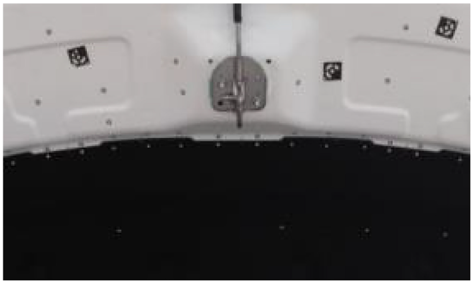
The calculation accuracy of the finite element model is an important factor affecting the fatigue life analysis. To verify the accuracy of the model, the torsional stiffness of the trial-produced prototype of engine hood assembly was tested, as shown in Figure 2. The comparison between torsional stiffness simulation and torsional stiffness test is shown in Table 1, which shows the simulation results of the engine hood are basically consistent with the test, and the error is within an acceptable range. Therefore, the accuracy of the finite element model of engine hood assembly meets the requirements.

Torsional stiffness test of engine hood.
Comparison of simulation deformation and test deformation under static load 80 N.

Finite element model and fatigue test verification of engine hood assembly
The finite element model of engine hood system including engine hood sealing strip, buffer block, engine hood hinge, engine hood lock, lock hook, and front longitudinal beam of vehicle body was established, as shown in Figure 3, including 203857 elements. The OGDEN material model was used for the model of the engine hood sealing strip, and the sealing force curve of the model was consistent with the measured value by adjusting the model parameters.

Finite element model of engine hood system: (a) view from the bottom and (b) bird’s eye view.
The finite element model was adjusted according to the internal engine hood test standard setting, so that the closing speed and energy of the engine hood were consistent with the fatigue test of the engine hood. The RADIOSS solver of Hyperworks software was used to calculate the force curve at the lock hook during the closing process of the engine hood, as shown in Figure 4. The S-N curve of the inner plate material of the engine hood is shown in Figure 5. The fatigue life at the lock hook of the engine hood was the lowest according to Femfat for life calculation, as shown in Figure 6. The simulation shows that fatigue damage will occur when the engine hood is opened and closed about 4000 times, which is lower than the design and user’s requirements of 5000 times. There is a high risk of fatigue durability, which does not meet the design and test requirements.

Force curve of lock hook when engine hood is closed.

The S-N curve of inner plate material of engine hood.

Fatigue life simulation of engine hood.
The prototype of the engine hood was installed on the same platform body, and the switch fatigue test was carried out. After the engine hood was turned on and off 3466 times, the metal plate of the engine hood lock hook strengthening plate cracked, as shown in Figure 7. The fatigue life simulation of the engine hood assembly was 4000 times. Therefore, the results of the simulation and the test are within the allowable range, and the accuracy of the simulation model meets the calculation requirements.

Fatigue test of engine hood: (a) prototype vehicle and (b) engine hood crack.
According to the fatigue life simulation and experimental verification, the reason for the crack at the lock hook strengthening plate of the engine hood was that the structural strengthening part is not covered to the crack area, and other structural designs fail to give appropriate life compensation. When the engine hood was turned on and off, the lock hook is subjected to the impact load of the lock, resulting in cracks in the inner plate sheet metal. Since the internal plate sheet metal material and material properties have been determined, the focus of improvement is to ameliorate the stress concentration of the engine hood assembly structure.
Analysis of influence factors on fatigue life of engine hood
According to the above analysis, the influence of the hook reinforcement plate structure, the height of the buffer block, the thickness of the inner plate, the thickness of the outer plate, the stiffness of the locking plate and the stiffness of the sealing strip on the fatigue life of the engine hood were studied respectively.
Lock hook reinforcement plate structure
According to the analysis of the section 2.2, the structure of the improved lock hook reinforcing plate is shown in Figure 8. The von Mises stress curve of dangerous element was extracted and the fatigue life was simulated by FEMFAT based on fatigue damage theory. Fatigue simulation of the improved engine hood is shown in Figure 9. The simulation displayed that fatigue damage will occur when the engine hood was turned on and off about 6800 times, which was about 1.7 times of the original design. The fatigue life of the upper end of the improved lock hook reinforcement plate was about 7100 times. Although the position of the original lock hook reinforcement plate was no longer the weakest position of fatigue, there was still a risk of failure. The maximum von Mises stress of the most dangerous element was 213.5 MP, and there are many dangerous points of stress concentration at the inner plate stiffener. Therefore, the scheme of improving the structure of the lock hook reinforcing plate has the risk of failure.

Look hook strengthening plate: (a) original structure and (b) optimized structure.

Fatigue life of improved engine hood.
Buffer block height
When the engine hood is closed, the height of the buffer block will directly affect the distribution of the impact load on the engine hood, thereby affecting the fatigue life of the engine hood. The simulation results are shown in Figure 10. As the height of the buffer block increases, the life of the engine hood fluctuates, and the maximum stress is mainly concentrated in the stiffeners of the inner plate. When adjusting the position of the buffer block, the fatigue life of adjusting 1 mm is similar to the fatigue life of the initial position, which is the best solution.

The relation curve between the displacement of buffer block and fatigue life.
Inner plate thickness and outer plate thickness
The effect of inner plate thickness on fatigue life of engine hood was simulated, and the simulation results are shown in Figure 11. With the increasing thickness of the inner plate, the fatigue life of the engine hood increases first and then decreases. When the inner plate thickness is 0.55 mm, the fatigue life of the engine hood is the largest. When the inner plate thickness is between 0.53 and 0.57 mm, the fatigue life of the engine hood is sensitive to the change of the inner plate thickness. Therefore, the inner plate thickness can maximize the fatigue life of the engine hood, which needs to be comprehensively considered in the actual design.

Relationship curve between inner plate thickness and fatigue life.
The fatigue life of the engine hood is simulated by changing the thickness of the outer plate, as shown in Figure 12. With the increase of outer plate thickness, the fatigue life of the engine hood increases first and then decreases. When the thickness of the outer plate is between 0.6 and 0.68 mm, the fatigue life of the engine hood is basically unchanged with the increase of the thickness of the outer plate. When the outer plate thickness is greater than 0.68 mm, the life of the engine hood increases rapidly, and reaches the maximum when the outer plate thickness is 0.72 mm. When the outer plate thickness is greater than 0.72 mm, the fatigue life of the engine hood decreases with the increase of the outer plate thickness. Therefore, the thickness of the outer plate can minimize the fatigue life of the engine hood, which needs comprehensively consideration in the actual design.

The relation curve between outer plate thickness and fatigue life.
Look hook stiffness and sealing strip stiffness
The stiffness of the lock hook directly affects the stress of the engine hood at the moment of closing. The simulation of the fatigue life of the engine hood by changing the lock hook stiffness is shown in Figure 13. With the increase of lock hook stiffness, the fatigue life of engine hood increases first and then decreases. The fatigue life of the engine hood reaches the maximum at the original design of the lock hook stiffness. Therefore, the lock hook stiffness can maximize the fatigue life of the engine hood, which needs to be considered comprehensively in the actual design.

Relationship curve between lock hook stiffness and fatigue life.
The main function of the sealing strip is to seal, with a certain stiffness, and play a supporting role in the process of closing the engine hood. Figure 14 shows that the fatigue life of the engine hood decreases slightly and then increases with the increase of the sealing strip stiffness. When the sealing strip stiffness is greater than 6.5 N/mm, the fatigue life of the engine hood decreases gradually. Therefore, the stiffness of the sealing strip can make the fatigue life of the engine hood reach the maximum, which needs to be comprehensively considered in the actual design.
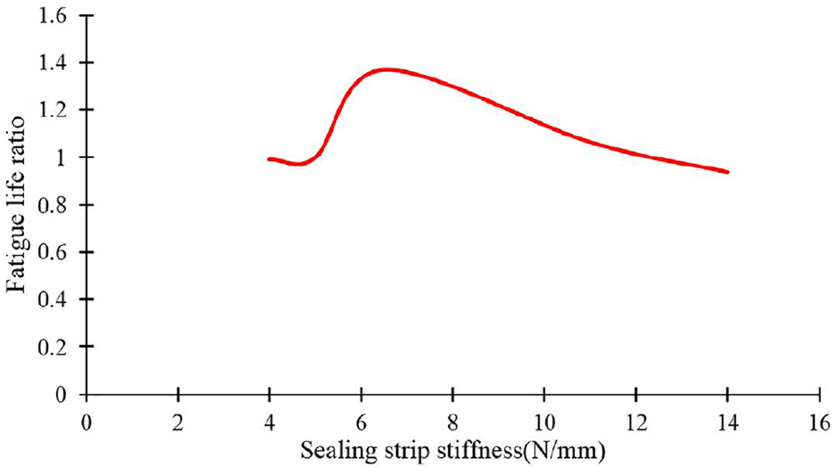
Relationship curve between sealing strip stiffness and fatigue life.
Multi-objective optimization
Model formulation of engine hood
The lightweight and fatigue life of engine hood was formulated as a multi-objective optimization problem based on a series of optimization parameters and constraints. The mathematical model of objective optimization is described as:

Where
According to the analysis of the five parameters variable characteristic curve ranges and the designer’s suggestion, the range of variability of each parameter shown in Table 2, was determined. The initial value is the value before engine hood optimization. The maximum and minimum values are the constraint values for the optimization calculation of each parameter variable.
Initial, minimum and maximum values of design variables.

Multi-objective particle swarm optimization algorithm
MOPSO is an extension of the standard particle swarm optimization algorithm (PSO) applied to single objective optimization problems.37,38 PSO is originated from research on the foraging behavior of birds. The position and velocity of


Where
When solving multi-objective optimization problems, standard PSO has the characteristics of low particle swarm diversity, easy premature and weak particle exploration ability in a wider range. Therefore, the standard PSO cannot directly apply the multi-objective optimization problem, and must be improved and extended on its own basis to form MOPSO:
Anyone in the Pareto set has a chance to be selected as a leader. The leader of each particle is randomly selected from the Pareto set according to the crowding distance;
At each iteration, Turbulence operator is used to perturb the speed of a small number of particles, which makes the potential flight directions of the particles more diverse, expands the optimization space of the particles, increases the probability of finding the global optimum, and expands the coverage of the design space;
External archiving technology that allows storage of non-dominant particles can spread and maintain the Pareto front.
The algorithm can be implemented by the following five steps and its flowchart is given in Figure 15.
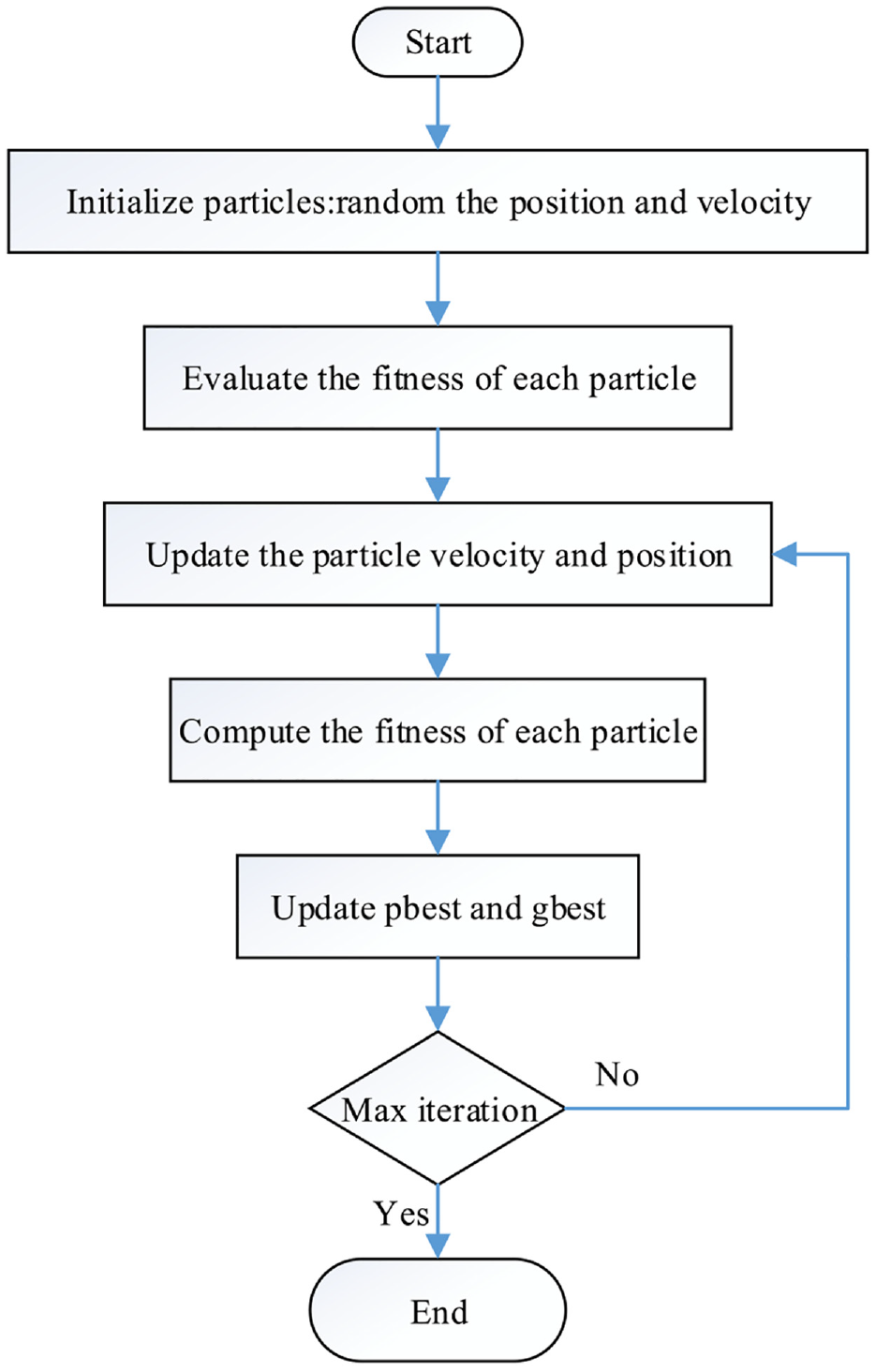
Flowchart of the MOPSO.
Then, the engine hood will be computed to show the process of the method step by step.
Step 1: Randomly initialize the position and velocity of each particle in the population.
Step 2: Evaluate the fitness of each particle, store the current position and fitness of each particles in the pbest, select all the individuals with the optimal fitness of pbest, and then store those individuals’ fitness and location in gbest.
Step 3: Use formula (2) and (3) to update the particle velocity and position.
Step 4: Compare the fitness of each particle with the best position it has experienced. If it is better, it will be the best location at the moment; compare all current pbest and gbest and update gbest.
Step 5: If the stop condition is satisfied, stop the search and output the result, otherwise return to step 3 to continue the search.
The particle swarm scale of the multi-objective particle swarm algorithm is 50. Number of iterations is 100. The Pareto front can be easily obtained by adopting MOPSO, as shown in Figure 16.

Pareto front.
Selected solution
In order to obtain an optimization that is ultimately applied to engineering, a compromise between the weight and the fatigue life of the hood needs to be selected from the Pareto set, that is, the BCS for engine hood. Fuzzy theory can help decision makers effectively select the BCS from Pareto set based on fuzzy mechanism. The membership function in fuzzy theory is expressed as:

Where

Where
According to the equation (5) of the dominance function, the dominance value of each non-dominated solution in the Pareto set can be obtained, and the results of the dominance value are shown in Figure 17. The dominance value reflects the comprehensive performance of the non-dominated solutions, and the solution with the largest dominance value is the BCS. The fatigue life of the engine hood corresponding to the maximum dominating function No. 9 is about 8400 times, and the mass is about 13.57 kg, as shown in Figure 16.

Dominance function.
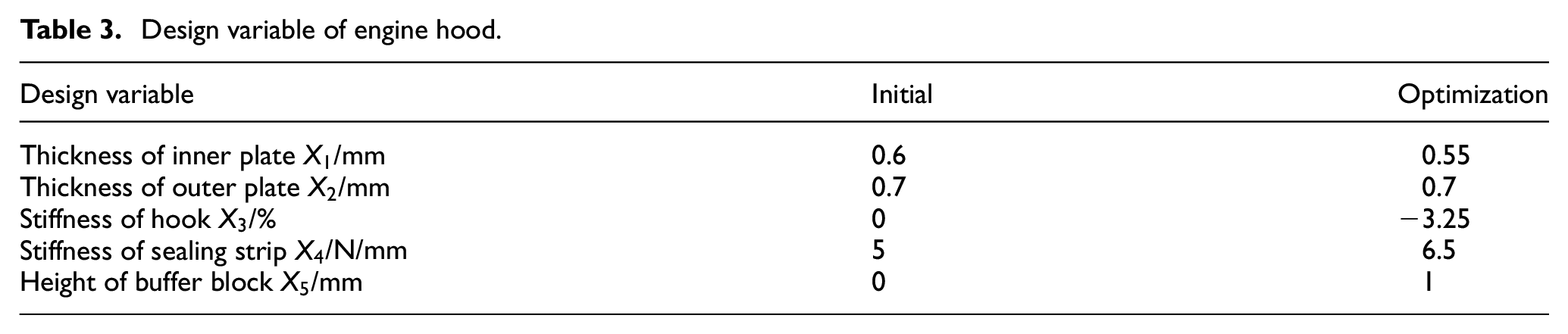
Considering the limitation of steel plate material specifications, molds and cost,the No. 13 hood with the same fatigue life as the No. 9 hood was trial-produced. The design variables are shown in Table 3. The mass of No. 13 engine hood is about 13.98 kg, which is 0.41 kg more than that of No. 9 engine hood. However, considering the model calculation error of 15.4% in the section 2.2, No. 13 is selected to ensure that the engine hood can simultaneously meet the requirements of design fatigue life of 5000 times and lightweight.
Design variable of engine hood.
The optimized engine hood simulation shows that the dangerous point of the inner plate is in the area of the locking hook reinforcing plate, and the maximum von Mises stress of the dangerous unit is 208.9 MPa, as shown in Figure 18. The stress of the dangerous point after the optimization of the engine hood is reduced compared with that before the optimization. The fatigue life is about 2.1 times that before optimization, and the stress of other parts of the engine hood has also been improved. The mass of engine hood assembly is reduced by 0.51 kg compared with that before optimization.

Von Mises stress at original danger point after optimization.
Experimental verification and discussion
According to the optimized compromise scheme, No. 13 was selected for the trial production of engine hood prototype. The torsional deformation test of engine hood was carried out, and the comparison of simulation and test results before and after optimization is shown in Table 4. Although the torsional deformation of the optimized engine hood was slightly increased, it also met the design requirements for engine hood deformation and the optimization requirements for constant stiffness.
Deformation comparison under static load of 80 N.

The engine hood prototype was installed on the vehicle for the engine hood switch fatigue test. After the engine hood was turned on and off 5000 times, there is no crack at the reinforcing plate of the engine hood, as shown in Figure 19. The engine hood was dismantled and inspected, and there was no fatigue durability damage, which verified the correctness of the optimized improvement plan.
Fatigue test of optimized engine hood.
In order to verify the accuracy of the calculation results, the fatigue test of engine hood continues until fatigue failure occurs. After the engine hood was turned on and off 7534 times, the sheet metal crack at the position of the locking hook reinforcing plate, and no fatigue damage was found at other parts after the disassembly and inspection of the engine hood, as shown in Figure 20. The fatigue life error between the multi-objective optimization calculation and experiment is 11.49%, which proves the correctness of the optimized method.
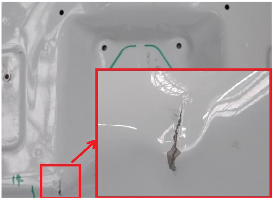
Crack of optimized engine hood.
Conclusions
A multi-objective structural optimization of the engine hood is carried out in this paper, considering both lightweight and fatigue life, with the overall goal of minimizing the overall weight and maximizing the fatigue life. The factors affecting the fatigue life of the engine hood are analyzed, and five engine hood parameters, such as the thickness of the inner plate, the thickness of the outer plate, the stiffness of the hook, the stiffness of the sealing strip, and the height of the buffer block, were selected as design variables. The deformations of engine hood were imposed as the constraints.
The optimization process was performed by the MOPSO and Pareto front were achieved. The fuzzy membership function fully mines the information contained in the Pareto frontier distribution, and combines the steel plate material specifications, molds and cost constraints to achieve a scientific compromise plan selection;
Switch fatigue test verification was performed according to the optimized parameters. The test results show that compared with the original engine hood, the fatigue life is increased by 117%, the mass is reduced by 0.51 kg, and the torsional deformation of the engine hood does not increase significantly. The combination of Multi-objective structural optimization and optimization algorithm can quickly and effectively find the structural parameters and the performance parameters that meets high fatigue life and lightweight, saving the cycle and cost of calibration.
Footnotes
Handling Editor: Chenhui Liang
Declaration of conflicting interests
The author(s) declared no potential conflicts of interest with respect to the research, authorship, and/or publication of this article.
Funding
The author(s) disclosed receipt of the following financial support for the research, authorship, and/or publication of this article: This research is supported by the National Key Research and Development Program of China (Grant no. 2018YFB0106200).