
Abstract
Expensive tooling often constraints the use of composites in the design and development of automotive parts. While there is significant confidence and knowledge in sheet and bulk metals, composite processes are less understood in mass production environment. The processes used to produce composites and resulting properties are influenced by fiber length attrition, resin to fiber ratio, process waste etc. Tool designs are determined very early in the engineering process. It is cost prohibitive to build additional tools, in the event it becomes obvious a better processing method and material would be beneficial, the original decision is not easily changed. In the present work we recognize the bottleneck of tooling costs and provide an approach of multi-process tooling. The innovation of this work is the design and demonstration of a single tool for different processes namely injection, injection-compression and extrusion-compression. The materials used in this study were long and short fiber thermoplastics (LFTs and SFTs). The resulting structure-property relationships have been reported for the materials and processing methods with a battery tray (BT) tool.
Introduction
There is increasing interest in high performance parts in automotive and related applications with technologies that lower greenhouse gas emissions. 1 Discontinuous and continuous-discontinuous hybrid composites are prime candidates for light weighting and thereby lower energy consumption. 2 The broad range of applications include but not limited to- interior, under the hood, roof, floor, and side body structures. In several cases these are non-cosmetic but highly structural load bearing components. 3
The timeline for automotive life cycle, from design to end of production (EOP) is long as shown Figure 1. The design phase begins a minimum of 4 years prior to start of production (SOP), and at 2 years, the request for quote (RFQ) is sent to suppliers, parts are awarded, and tooling kicked off. At 1 year, first articles are manufactured and engineering modifications made. Production begins, and typically lasts over 5 years, however programs can be extended up to five additional years or components are carried over for multiple generations. Essentially advancement halts in 7–10 years, depending on when material and process decisions are made without capital investment. This could be 20 years for carry-over components and 14 years for extended programs.

Typical developmental cycle of automotive components.
The present practices in tool design are determined very early in the engineering process. This is because it is cost prohibitive to build additional tools, in the event it becomes obvious a better processing method and material would be beneficial, while the original decision cannot be easily changed. New materials or components are often difficult to integrate into current programs, particularly if the processing of the new material(s) is different from the current.
Decisions made early in the automotive design process influence materials selection, which in turn dictates process, and subsequently tool design(s). Because of the tool build time and cost of tooling, the original path is not easily altered, even if there is compelling evidence another material or process would be beneficial. For example, if we assume the original decision is to make a component with long glass fiber (50 mm) and polypropylene (PP), and the process chosen is compression molding. However, in course of production it is realized that injection molding the part with 13 mm carbon fiber (CF) (40%) and PP would offer weight reduction of 25%, and still meet performance requirements, the tooling investments have already been made. Further, tool lead-time and cost constraints, can and would influence this decision.
The current work focuses on discontinuous fiber (DF) reinforcements. DFs include long fiber thermoplastics (LFT) and shopped fiber thermosets. DFs provide a lightweight replacement for metals or as an engineered substitute for other materials.4–6 The high aspect ratio of the reinforcement (fiber length divided by fiber diameter, l/d) results in increased stiffness, strength, and durability of the composite. DFs are typically used in automotive parts such as door panels, bumpers, instrument panels, under the hood components, floor and roof structures. 4
In the current work, a representative battery tray cover abbreviated as “BT” tool was used to study property bounds of DF composites produced via multiple processes including injection molding (IM), injection compression molding (ICM) and extrusion-compression molding (ECM). The BT tool design was conceived to be agile for use in multiple processes, that is, IM, ICM, and ECM. The material forms include LFT and short fiber thermoplastics (SFT). The BT tool design allows for the manufacture of prototypes with the most efficient processes or materials, without building multiple single process tools. The data generated by this study provides a baseline for the development of components with DF carbon composite materials and processing options without having to invest in multiple tools.
Processes
Different processing conditions were considered in the study:- (a) IM where two tool halves are clamped together in a press, and hot material is injected into the cavity and cooled, press is opened, and the part is removed7–9, (b) ICM which is similar to IM, but the tool cavities have a set gap, after the material is injected into the cavity the press is closed 10 ; and (c) ECM which is similar to compression molding (CM) with hot charge (fiber-polymer melt) where the fiber-polymer pellets are homogenized through a low shear plasticator (low shear extruder).4,11
Each of this process has inherent benefits and draw backs. Factors such as material type, fiber to resin ratio, fiber length attrition, fiber fracture in the process, and cycle time influence the resulting composite. This paper is divided into two parts:- (a) tool design and unique features of the BT tool, and (b) characterization of composites made with the different processes on this BT tool. The study paves the path to apply multiple processes in a single tool reducing cost and development time of complex shaped multi-scale (discontinuous versus continuous) composites.
Multi-process tooling
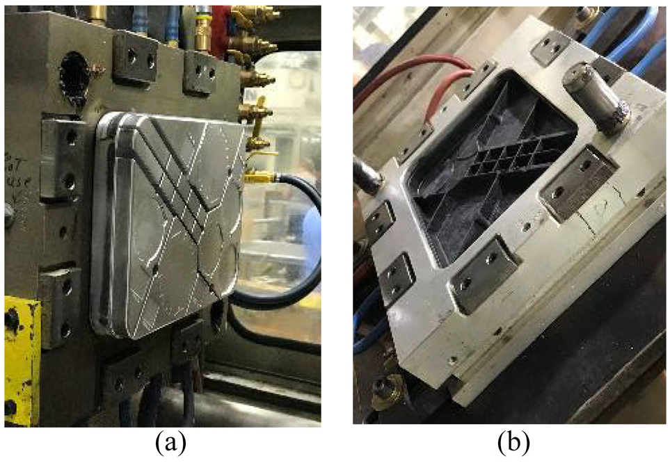
The BT tool section shown in Figure 2(a) and (b) is designed to provide a range of materials evaluation options without incurring multiple tooling cost for each process, IM or CM. The same tool is used for IM and CM in this work, hence the term multi-process tool. When considering the differences between IM and CM processes- (a) the IM tool typically has two mating halves as illustrated in Figure 2(a). The core and cap seal against each other forming a parting line, the vent allows gases to escape as the cavity is filled. The tool is closed on stops and the tolerance (gap) between the mating halves is 0.098 mm. The bypass shear edge shown by an arrow in Figure 2(a) enables to “pack” the charge in the fixed cavity for IM; (b) when the same tool is used in CM the tool halves are dynamic, i.e. the core is moving toward the cavity (unlike a fixed cavity for IM). The tool halves have a higher gap of 0.5 mm (compared to 0.098 mm for IM) to enable venting between the mold halves as the charge is packing.

Illustration of the cut-through of the BT tool. (a) Tool closed on stops with 0.098 mm gap between mating halves used in IM; (b) tool with 0.598 mm gap between mating halves used in CM. Arrows in (a and b) show bypass shear edge effective in packing the charge to achieve high compaction in both IM and CM.
Multi-processes tool considerations (bypass shear and its importance)
Conventional two cavity molds are constructed with a bypass shear edge. The shear edge helps contain and “pack out” (or completely fill) the mold with the material (“charge”). The bypass shear is typical of thermoplastic sheet compression molds, but is usually only 1–2 mm. The bypass shear has been significantly increased (∼10 mm) in the present work as illustrated in Figure 2(a) and (b) to provide enhanced packing of the material. External stops have been added to ensure a constant part thickness as shown in Figure 2(a). Sprue bushing on the tool are used for IM while a filler plug is used for CM. For IM the bypass shear also reduces the flash on the parting line and wear on the mating surfaces. Because parts may vary in shape, size and wall thickness, the by-pass engagement needs to be accurately determined for use in IM, ICM, and ECM. Although not considered here, the same is true of thermoset DFs such as sheet molding compound (SMC) and bulk molding compound (BMC).
The design of the bypass edge is guided by the following steps:- (a) Mold flow analysis is used to determine at what fill percentage the resin/fiber reaches the perimeter at any point at fill when tool is closed; (b) The final wall thickness is divided by the fill percentage to determine minimum by-pass engagement with a 2 mm added to the thickness. An additional 2 mm is further added to ensure the by-pass is engaged before resin/fiber reaches the part perimeter, that is, final wall thickness is 4 mm. For example, in mold flow if the resin reaches the perimeter at 48% fill, 4mm/0.48 = 8.33 mm + 2 mm = 10.33 mm is the by-pass engagement.
To eliminate flash at the by-pass parting line, the maximum tool gap is calculated to be 0.0254 mm (0.001″). The tool temperature of core side and cap side must be relatively the “same,” so that both must move together (up or down). Because of thermal expansion the core side must be equal to or less than the cap side. There is some latitude based on metal expansion to allow for the core side to be slightly higher than the cap side, but this safety factor is not forgiving on larger tools, even though they are made of steel. If the cap side becomes higher than the core side, tool damage will not occur, but excessive flash will begin to develop as the temperature differential grows.
The unique design in the present work eliminates internal venting, see Figure 2. A bypass shear is incorporated with enough engagement to create a flow front in either of the compression processes (ICM or ECM), with minimal shear gap for the injection process. The entire perimeter of the parting line is a vent.
Materials and methods
The BT tool shown in Figure 3(a) to (d) used in this work is approximately 355 mm × 279 mm (14″ × 11″) with a range of features. Various features of the BT tool include a flat base, different elevations (height) extending out of the base, circular features, and ribs of various thickness and sizes, see Figure 4. The rib geometries were designed to enable higher material permeability in the thicker ribs and restriction to flow in the thinner ribs, Table 1. The parts were characterized for flexure (ASTM D790) and interlaminar shear strength (ILSS) (ASTM D2344) per ASTM standards by extracting samples from selected portions of the tool. The testing was carried out on a Test Resources (Minnesota, MN, USA) load frame with 50 kN capacity load cell. The tool was mounted to the IM or CM presses based on the process used to produce the part. The material flow, fiber orientation and its effect on properties in the base versus the ribs etc. are examples of the parameters that were studied for any given process of interest.

Representative multiple process BT tool used to produce long fiber IM, ICM, and ECM part. The part features thick, thin ribs, thin-thick base areas, channel variations, and features that provide understanding of material flow through the cavities. (a) CAD detail of the BT tool; (b) part detail; (c and d) typical molded PA6-CF parts with ” starting fiber length pellets. Part size is approximately 355 mm × 280 mm (14″ × 11″).
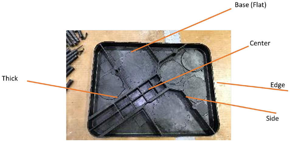
Nomenclature for identifying the various features of the BT part.
Part geometry and details.

Different material systems were investigated in this study including (a) Commercial LFT (or LCF stands for Long Carbon Fiber) from Plasticomp Complēt®. Several variants include- LCF40-PA66 and LCF50-PA66 is a 40% and 50% by weight long carbon fiber reinforced nylon 6/6 (polyamide 6/6) thermoplastic composite manufactured using a pultrusion process that melt impregnates the fiber with the matrix resin; (b) Commercial LFT from Plasticomp Complet LCGF50 – PA66 with 25%glass and 25%carbon fiber by weight respectively; (c) Textile grade carbon fiber (TCF) compounded PA66. The TCF is a low-cost carbon fiber pioneered at the Carbon Fiber Technology Facility (CFTF) at Oak Ridge National Laboratory (ORNL), Oak Ridge, Tennessee, USA for non-aerospace markets. 30 wt% TCF-PA66 pellets were produced in a compounding twin screw extruder at Techmer PM, Clinton, Tennessee, USA. Table 2 summarizes various process details for these processes. Table 3 summarizes the design of experiments conducted with these variants.
Processing conditions for different processes.
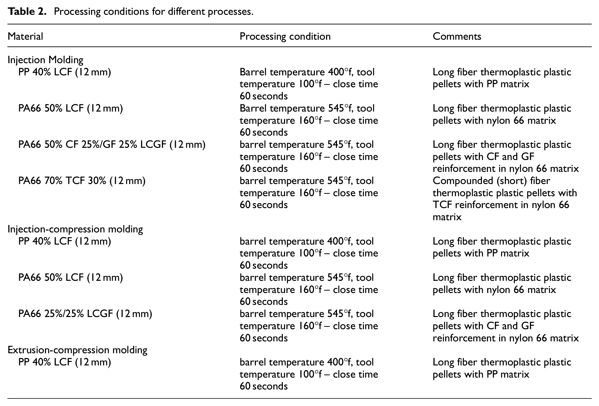
Design of Experiments with Multiple Process BT tool.

Results and discussion
Injection molding
A 400 metric ton Van Dorn Injection Mold Press (Figure 5) with 60oz shot size was used in producing the BT parts. Representative short shots shown in Figure 6 illustrate the flow and fill of the LFT charge. During short shot runs is can be seen that there is some degree of non-uniformity in the fill as the process was still being dialed in. The corners are the last to fill. The thin 2.7 mm ribs did not fill in the first few attempts.
Injection molding BT tool halves; (a) cavity side; (b) core side with a molded part waiting to be ejected. Part size 355 mm × 280 mm (14″ × 11″).

Short shot runs to evaluate fill trends in multi-process BT tool. (a and b) Good rib definition is verified, Preferential flow along ribs, corners are last to rill; (c) Confirmation of full fill with trial and error, indication of flash which guides final process conditions.
The rib fill challenges guided the adjustments required in setting the parameters to achieve full fill. Short shots are customary in injection molding trials to evaluate the flow front and freeze off. In such case, less material (charge) is injected (or extrusion-compression molded) in the tool to obtain less than full tool coverage. This provides valuable insight into the flow fronts and fill. This information is also used in modeling of the flow field by designers. In the present study, the “charge” was incrementally increased from “partial fill” to “full fill” as illustrated in Figure 6. With several trial-and-error runs, the process was iteratively established to achieve full fill as shown in Figure 6. Figure 7 illustrates a representative molded part with the sprue still attached. Figure 7(a) shows the sprue location where fiber-resin charge was injected into the cavity. Figure 7(b) is the underside of the part. The definition of the ribs on the underside was excellent. No print through was observed once the process was finalized. Figure 7(c) is the face of the part again indicating excellent coverage and uniform flow. It may be noted that the location of the sprue was sealed off to use the tool for CM.
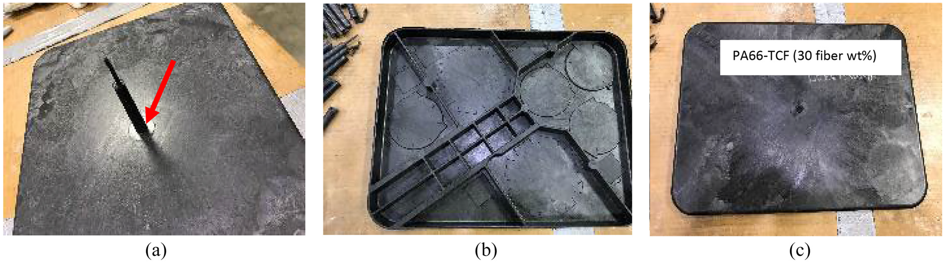
Representative BT part with full fill. The part shown is 30% fiber weight, PA66- TCF long fiber thermoplastic composite; (a) Sprue, location of fiber-resin charge injection; (b) Underside of the part showing excellent rib definitions; and (c) Front side of the part showing full material coverage. The final parts were molded to similar appearance and repeatability.
Injection-compression molding
In ICM fiber-resin melt is introduced into a gap mold with simultaneous or subsequent compression by an additional clamping stroke, see Figure 8. 10 The cavity pressure build-up in the mold is distributed in two dimensions more uniformly over the projected component surface. Wang et al. studied cavity pressures in conventional IM and ICM and reported that ICM can greatly decrease the injection pressure and cavity pressure and make the cavity pressure field more uniform. During processing of reinforced thermoplastics in ICM, due to lower pressure (30%–40% lower), the fibers are subjected to less shear attrition than IM. This results in fiber length retention and thereby higher mechanical properties. 4 Further ICM enables higher weight fraction packing >50%Wf (50% is generally the limit for IM) and lower overall energy consumption. Also, ICM has low residual stress and less warpage compared to IM. Due to low-pressure decorative film in-lays or metal inserts do not get damaged in ICM. In the current work, the tool gap for the ICM runs was set to 6 mm at fill.

Uniform pressure distribution in ICM compared to IM; (a) IM – fluid center hydrodynamic 200–700 bar; high pressure in the vicinity of the injection sprue reducing outward; (b) ICM – clamping unit/die roughly hydrostatic 50–300 bar. Uniform pressure maintained across the cavity.
Extrusion-compression molding (ECM)
Traditional CM is conducted in a two-cavity tool with the tool halves mounted to the top and bottom cavity of a compression press. There is a wide range of press capacities, typically for the application in this work, a 200–400 metric ton press with platen sizes 0.91 m × 0.91 m (36″ × 36″) and day light opening of 0.762 m (30″) or greater can be used. In pure compression, the material is placed or transferred to the press and the platens are closed at a closing speed of 1.9 m/min–3.8 m/min (75–150 in/min). The material flows under pressure and fills the cavity.
In ECM, a variant of CM, a plasticating extruder is used to homogenize the LFT materials. The low shear action on the plasticator causes minimum fiber attrition. The charge has the shape of a “log” at the end of the extruder which is collected and placed in the compression tool. The material flows under pressure and heat and fills the cavity similar to CM.
A Plasdan Shot-Pot extruder (also can be used as a high capacity injection unit) with a 20 oz barrel (see Figure 9) was used to produce the extruded charge. 11 The charge was collected and fed to the BT tool mounted on a Williams, White & Co. press (see Figure 9) used for compression and extrusion/compression. The press is a double platen up acting 200 metric ton per side.

(a) Plasdan extruder with 20 oz barrel ; (b) Williams, White & Co, Double platen 400 metric ton compression press.
Mechanical testing
Various compositions were manufactured as summarized in Table 2. Flat specimens from the surface of the BT tool were extracted out of different variants of parts manufactured from IM, ICM, and ECM on the multi-process BT tool. These can be considered as baseline coming from the flat region of the BT tool. Not every variant was possible to test for every process. However, representative specimens were tested as possible to evaluate the trends.
For IM, ICM, and ECM parts, test specimens were extracted “along” (0°) and “across” (90°) the fiber flow direction as illustrated in Figure 10. In general terms, the 00 direction is “along” the long side (14″ side) of the BT part. Flexure, interlaminar shear, and Izod impact specimens were extracted from the flat surface of the BT part per respective ASTM guidelines. The flexure (ASTM D790) specimens had dimension of 100 mm × 12 mm × 3.125 mm with a span of 60 mm and the loading rate of 0.01 mm/min was used. The interlaminar shear (ASTM D2344) specimens had dimension of 40 mm × 12 mm × 3.125 with a span of 25 mm with a loading rate of 0.01 mm/min. The Izod impact (ASTM D256) had specimen dimensions of 70 mm × 12 mm × 3.125 mm with maximum energy 50 J.

(a) Surface test specimen extraction on battery tray parts. Specimens were extracted “along” and “across” the fiber orientation of IM, ICM, and ECM samples. (b) Flexure specimens from ribs and edge were also extracted from various ribs locations for IM, ICM, and ECM parts.
Flexure test specimens from ribs were also extracted, as shown in Figure 10 from various locations of IM, ICM, and ECM parts, and tested per the corresponding ASTM standard. A Test Resources load frame with 50 kN loadcell was used. An average of five specimens were tested per test type.
Flexure testing: Flexure data of IM, ICM, ECM of variants processed on the BT tool are presented in Figures 11 and 12. Test specimens extracted “along” and “across” the fiber orientation were tested uniformly. Several observations can be made- (a) Flexure properties range: The IM specimens “across” the board ranged in flexural strength of 100–250 MPa; and flexural modulus 3–18 GPa depending upon the location of the sample, that is, “along” or “across” the flow direction; (b) Effect of directionality: The “along” direction specimens exhibited up to 40% higher values than “across” indicating high degree of fiber orientation in the flow direction; (c) PP versus PP66: Between the PP and PA66 systems, the PA66 exhibited about 30% higher values than the PP based specimens. Interestingly the glass fiber – carbon fiber hybrid (25C-25G-50PA66) exhibited the highest flexural strength of 250 MPa and high flexural modulus ∼15 GPa; (d) TCF based: TCF-PP specimens showed lower strength and modulus compared to PA66 composite specimens as PP matrix has lower stiffness than PA66. In the “along” direction, the 30 wt% TCF-PA66 had superior properties (200 MPa) and compared in flexural strength to commercial 50 wt% CF-PA66 material. This indicates that the fiber orientation is a dominant factor over extent of fiber attrition during the IM process; (e) IM versus ICM: The ICM 50% CF-PA66 exhibited 11% higher flexural strength than the IM 50% CF-PA66. The 50% CF-PA66 ICM also had the highest flexural modulus of 18 GPa across all the specimens tested. The high performance of the ICM specimens is attributed to lowering of the shear force on the fiber during the injection process; (f) IM versus ECM: The ECM 40% LCF-PP was 15% higher in average flexural strength than the IM 40% LCF-PP and exhibited a high flexural modulus of ∼17 GPa. Although ECM results in more pseudo-random fiber orientation, the difference could be attributed to lower fiber attrition in the ECM compared to IM and some degree of directionality “along” the flow direction. These are within the statistical difference of each other. Fiber length retention is higher the ECM specimens, overall stiffness (modulus) is higher than IM specimens. Failure modes were evaluated as per ASTM D790 requirements.
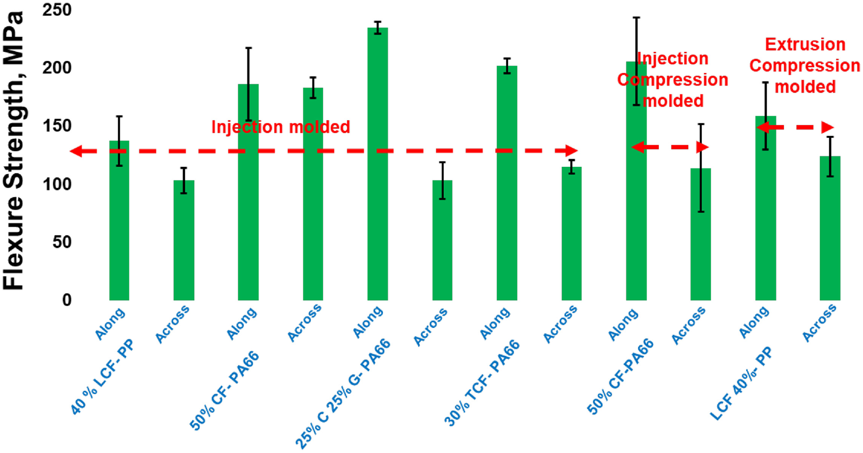
Flexure strength of all the variants processed on the multi-process tool.

Flexure modulus of all the variants processed on the multi-process tool.
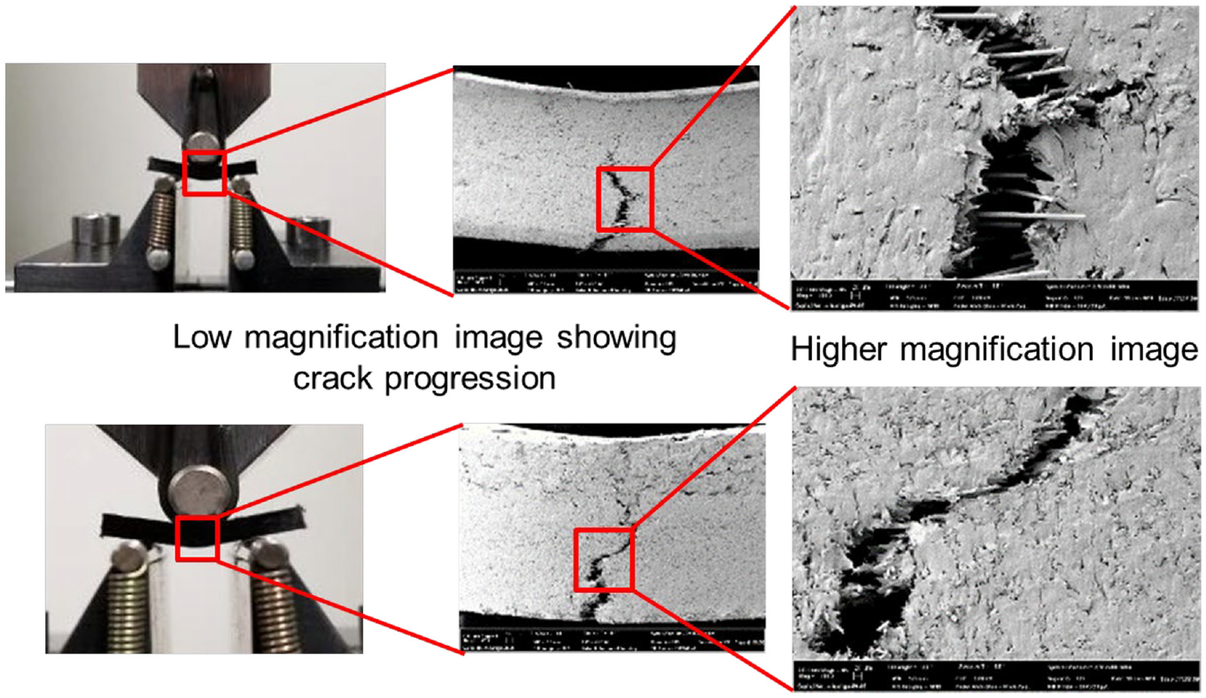
Figure 13 shows typical failure mode for representative specimens tested in flexure. For all the specimens tested, the failure occurred through tensile side fracture. The samples exhibited excellent ductility as evidenced from the Figure 14 attributed to being a thermoplastic matrix. The crack initiated on the tensile side and propagated across through the thickness until the specimen stopped carrying load. Multiple fibers were seen bridging the crack faces indicative of good fiber/matrix bonding resisting failure. Only one example is shown here to avoid repetition.

Typical failure analysis of flexure specimens observed with high resolution SEM at low and high magnification. Failure mode of the specimens were as per ASTM D790.
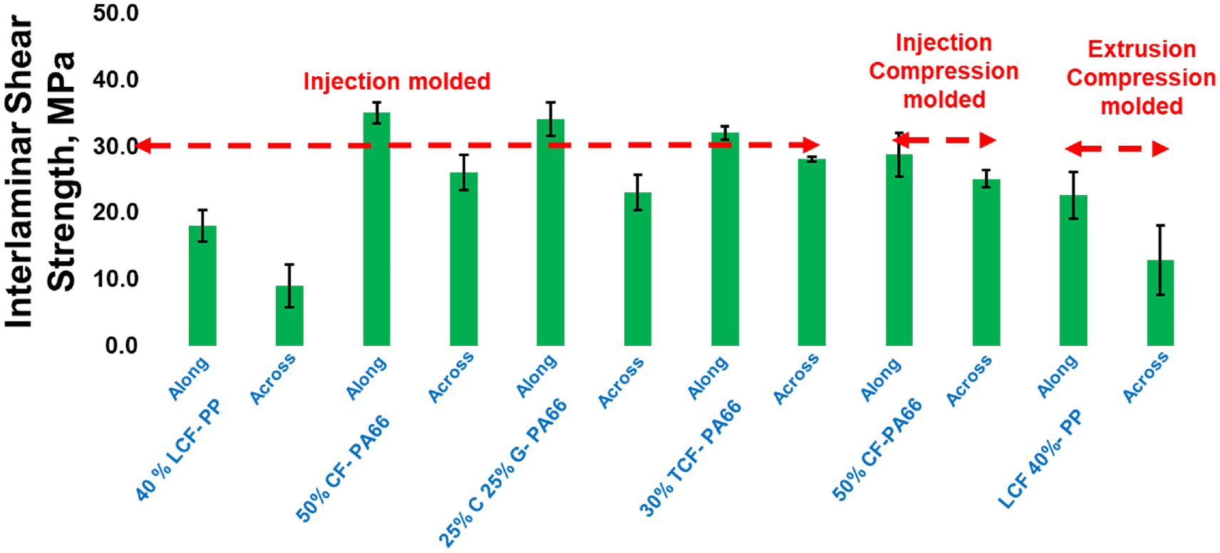
Interlaminar shear (ILS) strength of all the variants processed on the multi-process tool are presented. The ICM and ECM processed samples showed higher ILS strength compared to IM processed variants. In hybrid variant there was reduction in the ILS strength compared to IM specimens.
Interlaminar Strength: Interlaminar shear (ILS) strength of IM, ICM, ECM BT specimens are presented in Figure 14. Test specimens extracted in “along” and “across” fiber orientation were tested uniformly on ILS test fixture, Figure 15. All the variants for the “along” direction show approximately 30 MPa of ILS strength, showing good bonding between the fiber and the matrix, except for the LCF- PP specimens. Lower ILS strength could be due to poor bonding between the C-fiber and PP matrix as PP is hydrophobic most of the surface sizing are not compatible with PP matrix. Failure mode analysis of ILS tested specimens were observed as per ASTM D790 requirements. Figure 15 show typical ILS failure mode.
Typical failure modes of ILS specimens observed with high resolution SEM at low and high magnification. Failure mode of the specimens were as per ASTM D2344.
Testing of ribs and out of plane features
The ribs identification is provided in Figures 4 and 10 respectively as “center,”“side,”“edge” and “thick” ribs respectively. Flexure testing of these ribs was characterized per ASTM D790 and the data is shown in Figures 16 and 17. Flexure strength of the ribs indicate differences between the various ribs indicating effects of fiber directionality induced during process flow. Figure 16 indicates that the thick rib specimens had the highest flexural strength average of 180 MPa and average flexural modulus of 15 GPa. “Thick” rib specimens in all the variants (IM, ICM, and ECM) showed higher stiffness corroborating the orientation of fibers along the specimen direction. The “edge”“center” and “side” ribs had similar values of ∼120 MPa as average flexural strength and ∼5 GPa average flexural modulus. The “center” rib for the 25GF-25CF-PA66 ECM variant had a response similar to the thick rib which was a notable outlier. However, the standard deviation is high.
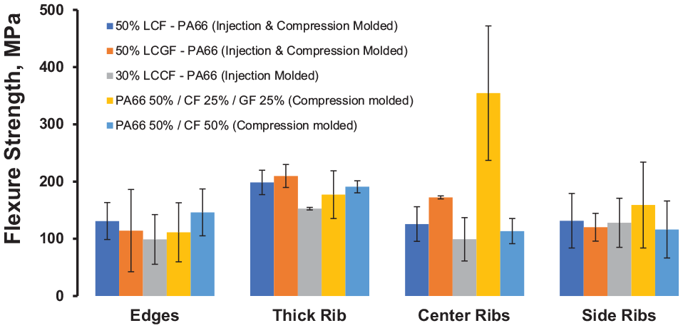
Flexure strength data of the ribs and edge specimen extracted from IM, ICM, and ECM battery tray parts.
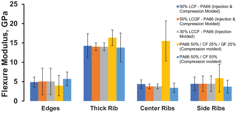
Flexure modulus data of the ribs and edge specimen extracted from IM, ICM, and ECM battery tray parts.
SEM analysis near the point of injection molding of IM and ICM parts further revealed that the upon injection, the fibers orient along the length of the ribs thereby enhancing the stiffness, Figure 18. Due to shear alignment of the fibers in the ribs overall stiffness of the part is enhanced. This capability also shows that preferential alignment of the fibers can be achieved by carefully designing ribs in the parts for enhanced stiffness.

Typical SEM images of the IM and ICM parts near the injection point showing fiber flow and orientation along the ribs for enhanced stiffness.
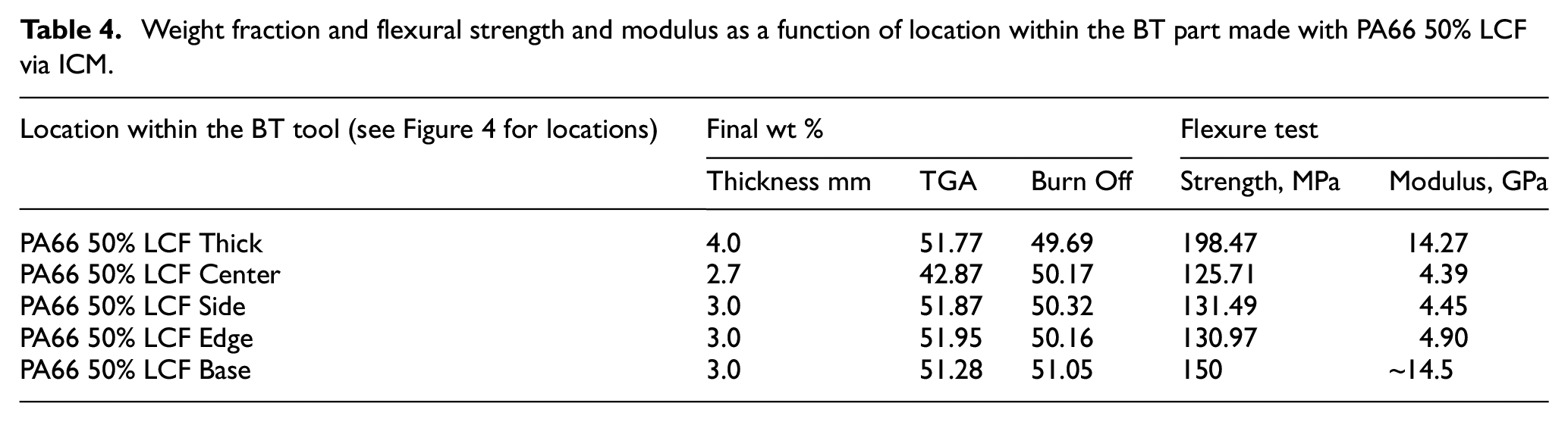
Figure 19 illustrates that base of the part, and the thick ribs show some variation from highly oriented fibers. In all other ribs, that is, side, edge, center the fibers are highly oriented along the rib direction as can be seen from the figure. Table 4 summarizes the respective weight fractions and it can be noted that the weight fraction are consistently in the 50wf% value. The side, edge, and center ribs show similar flexural strength and modulus. The thick ribs had some variation and outlier which is attributed to the variation in the fiber orientation.

SEM to illustrate fiber orientation at different locations on the BT part. The locations are the (a) base, (b) thick rib, (c) side rib (d) center rib, and (e) edge rib. Also refer to Figure 4 for the location(s) information.
Weight fraction and flexural strength and modulus as a function of location within the BT part made with PA66 50% LCF via ICM.
Discussion
Materials: The part stability in the different processes and materials provides significant insights into material flow, homogeneity, fiber orientation, and repeatable process. The tool enabled parts production for all three processes – IM, ICM, and ECM. The properties across these processes are comparable for each location of the study. Higher fiber length retention was observed in GF compared to CF. Hence for 25GF-5CF the higher bond strength of GF to CF results in higher strength and modulus retention. Compounded 30 wt% TCF exhibited comparable properties to commercia LCF indicating fiber attrition balances out the effect of the weight fraction. Higher weight fraction such as 40% and 50% LCF had higher standard deviation indicating higher fiber-to-fiber interaction and higher attrition.
Tooling: Potential weight savings– Because of light weighting efforts over the years, the easy, significant amount of weight has already been removed and replaced, the focus of automotive is shifting to grams of weight savings. The multi-process tool technology allows the removal of grams without waiting years for the next commercial opportunity. The technology is applicable to OEMs, Tiers, and part suppliers.
The cost of tooling is usually the bottleneck in innovation and part development. The ability to design and optimize product development with tooling applicable across multiple processes reduces significant costs. Taking an example of tooling for an automotive hood costing $120 k for injection molding, will now enable the same tool to be used in compression and injection-compression, thereby achieving the development at 33% of an otherwise iterative approach. The approach reduces the cost and cycle times of manufacturing.
Tailored part volumes: There is another inherent benefit from the by-pass shear edge tool design with external stop. The tool can be closed to any point by simply adding or removing shim from the stops. In the example above, the part volume is 392 cm3. If 1 mm is removed from the stops, the part volume is reduced by 21.4%. Taking advantage of this capability would depend on the form, fit, and function associated with each individual part.
Materials substitution: New materials are entering the marketplace at an ever-increasing rate, however the barriers in the automotive industry prohibit timely entry into the auto industry. Based on the test results in Figure 5, a seatback manufactured using the Profuse (polypropylene + glass) material using CM weighs 2 kg could be replaced with an IM version using recycled carbon fiber – PA66 (recycled carbon fiber + nylon) with a weight savings of 13.5% or 270 g per seatback. If there are four seatbacks per vehicle, this is a weight savings of 1080 g/vehicle.
Industrial relevance
The technical challenge was to prove a tool designed for IM, CM, ICM, and ECM therefore providing the customer a range of material evaluation options without incurring a separate tooling cost for each process. The innovation is the development and validation of a new tool design that allows a single tool to be used for multiple types of molding processes. This will be especially liberating in prototyping and may also prove to be quite valuable for certain production programs.
There are two challenges for automotive entry points- first is to allow for new materials to break into the automotive business cycle, this is easily calculated as the embodied energy cost to manufacture raw materials to make a new tool for the new process/material. This would also include the energy requested to shape the tool materials i.e. milling, grinding, heat treat. The other is the “forever cost” associated with accelerating a mass, if the new tool design allows for the transition to a light material, then for the life of the vehicle, with the lighter component, the energy to accelerate to speed is reduced.
One of the primary attributes of this work to create the forward-thinking culture in the design phase of tooling. The question the designer must ask is – What can be done to a tool designed for a specific process to enable its use in another process? It may be as simple as adding an insulating layer, allowing a cold tool designed for thermoplastics, to be heated and used for thermosets. Or adding a hole and channel for a gasket. Other than some additional thought, a little more machine time, and some inexpensive components, there is no significant cost.
Conclusions
This study presents and innovative approach of multi-process tooling and minimizing the cost of multiple tools to decide on a parts development strategy. This has major implications on cost-savings to the OEMs, Tier suppliers and end-customers. The key innovation in this work is a multi-process tool that can be interchangeably used across processes, that is, IM, ICM, CM, and ECM, without the need for separate tools. By shortening the lead time for introduction of new materials into the automotive product cycle, the benefits of lowering the energy are gained. Because of the cost of tooling and the inherent risk aversion of most manufactures, the best recommendation for any manufacturer with injection and compression capability is to make the next prototype tool based on this design concept. This will provide the confidence required to move to a production tool. Tool design can influence integration of new material technologies into the marketplace, by denying access based on new tool cost and timing. The embodied energy cost required to change processes, is a small part of the possible savings, the forever cost of accelerating each additional gram to highway speed is larger.
The LCF PA66 and TCF PA66 variants were successfully processed through three processes – IM, ICM, and ECM on the same tool. The LCF and TCF were comparable in terms of properties within each process for the locations of interest, for example, at a rib or the base, etc. The ribs were lower in strength than the base attributed to in-plane versus out of plane fiber movement. Packing density in the ribs exhibited lower properties at the edge than the center. Even through GF have lower modulus and strength, they exhibit higher fiber length retention, balancing out properties and improving in case of hybrid materials.
Footnotes
Acknowledgements
The authors would like to acknowledge the support of the Institute for Advanced Composites Manufacturing Innovation (IACMI) – The Composites Institute.
Handling Editor: Chenhui Liang
Authors’ note
Notice of Copyright This manuscript has been authored by UT-Battelle, LLC under Contract No. DE-AC05-00OR22725 with the U.S. Department of Energy. The United States Government retains and the publisher, by accepting the article for publication, acknowledges that the United States Government retains a non-exclusive, paid-up, irrevocable, world-wide license to publish or reproduce the published form of this manuscript, or allow others to do so, for United States Government purposes. The Department of Energy will provide public access to these results of federally sponsored research in accordance with the DOE Public Access Plan (![]() ).
).
Declaration of conflicting interests
The author(s) declared no potential conflicts of interest with respect to the research, authorship, and/or publication of this article.
Funding
The author(s) disclosed receipt of the following financial support for the research, authorship, and/or publication of this article: The information, data, and work presented herein was funded in part by the US Department of Energy, Office of Energy Efficiency and Renewable Energy, under Award Number DE-EE0006926. Parts of the tooling innovation is leveraged through the Department of Defense America’s Cutting Edge (ACE) award to The University of Tennessee.