
Abstract
Pre-chamber jet ignition technology can effectively improve flame propagation speed and in-cylinder combustion rate, so it is conducive to the improvement of thermal efficiency and fuel economy. While, studies on the key parameters of the influence of active pre-chamber on combustion and emissions are not systematic. The influence of the key parameters of injection control in active pre-chamber on combustion and emission is not clear at present. Thus, in this paper, an active pre-chamber jet ignition system was designed and used in a single cylinder GDI engine, and the effects of compression ratio and pre-chamber injection strategy on pre-chamber jet ignition were experimentally studied, as well as the comparison of pre-chamber jet ignition and conventional spark ignition. The results show that, at 2750 r/min, IMEP 11 bar operation point, lean burn can effectively reduce the fuel consumption and increase the thermal efficiency of gasoline engine. Adopting traditional spark plug system can extend the lean burn limit to excess air ratio of 1.5 with the gross indicated thermal efficiency (GITE) of 45% limited by unstable combustion, while resembling active pre-chamber system can achieve GITE of 46.5% with the excess air ratio of 2.0 with the help of much more stable combustion. And the NOx emission of active-pre-chamber system has been reduced by 78% compared by conventional spark plug system. Increasing the compression ratio to 14.8 can further reduce the indicated fuel consumption to 177 g/kWh, and increase the GITE to 48.5% and further reduce the NOx emission to lowest 0.53 g/kWh with the excess air ratio of 2.1. With the increase of pre-chamber injection pressure, the ignition stability increases, the combustion duration decrases, and thermal efficiency increases. With the increase of the pre-chamber injection duration, the ignition delay first decreases and then increases. When the injection duration increases to 800 μs, COV is greater than 3%. If the pre-chamber injection duration further increase, the COV increases, the combustion phasing retard, and the thermal efficiency decreases. With the increase of pre-chamber injection duration and pressure, the wetting wall fuel increases, which leads to the increase of PN emission.
Introduction
With global warming, more and more stringent vehicle fuel consumption and emissions regulations have been formulated. Alternative fuels, hybrid and higher efficiency engine are effective ways to further realize energy saving and emission reduction.1–3 Lean burn is one of potential technologies for high efficiency engines in the future. Compared with stoichiometry combustion, lean burn increases the specific heat capacity by adding excessive fresh air to the cylinder, it can improve the theoretical thermal efficiency, and reduce pumping losses. Moreover, lean burn can reduce the combustion temperature, it helps to reduce the heat transfer losses, and simultaneously inhibit the spontaneous combustion of the mixture in the cylinder, thus inhibiting the generation of detonation, so the compression ratio can be further improved.4–10
Under the above beneficial effects of lean burn technologies, the effective thermal efficiency of engine can be extended to more than 45%.11,12 Several OEMs have released the ultra-high thermal efficiency concept routes.11–13 For example, Toyota’s 45% thermal efficiency technical solution method mentioned lean burn technology. 11 Nissan’s e-Power engine can achieve 50% thermal efficiency using lean burn as one of the key technologies. Japan’s SIP Alliance uses technologies such as lean burn and thermal insulation coating to further increase the effective thermal efficiency to 51.5%. However, as lambda increases, the combustion rate decreases, and the development of initial frame core becomes more difficult. Conventional spark ignition is difficult to extend the lean burn limit, which limits the fuel saving potential.11,14–16
The pre-chamber jet ignition technology first ignites the combustible mixture in a small space, and the high-temperature and high-pressure mixture in the pre-chamber is sprayed into the main combustion chamber through small holes, thereby igniting the main combustion chamber mixture. There are three reasons why the pre-chamber achieves fast and stable combustion: the sprayed high-temperature, high-pressure mixture increases the ignition area; the flame sprayed through the small holes is extinguished, producing active combustion intermediate products and increasing the combustion rate; the turbulent kinetic energy of the main combustion chamber is increased by high-speed sprayed mixture.17,18 Thus, pre-chamber jet ignition technology can improve the disadvantage of lean burn.19–22 It is one of the most potential technologies to achieve ultra-high thermal efficiency and low emissions in the future. In recent years, with the increasing requirements for the thermal efficiency and power performance of gasoline engines, the research on the pre-chamber of the gasoline engine is increasing gradually. The results of MAHLE show that the flammability limit of traditional spark ignition is about lambda = 1.4, and the combustion duration is significantly prolonged at this time. While, using pre-chamber jet ignition technology can realize the rapid and stable combustion in cylinder, lambda limit can be extended to more than 2.23,24 Both numerical and experimental results of FEV 13 show that, compared with traditional ignition technology, the indicated thermal efficiency of pre-chamber jet ignition is improved. The improvement of thermal efficiency benefits from the expansion of the limit of lean burn. FEV 25 used a single cylinder engine to carry out experimental research on the active pre-chamber. The results show that the fuel efficiency can be maximized due to the rapid and non-knock combustion of the active pre-chamber. At the Lambda = 2 condition, the indicating thermal efficiency reaches 47%. At the same time, FEV indicated that the use of electronic supercharging system was expected to increase the limit of lean burn, so the indicated thermal efficiency can be improved to more than 48%. Honda 26 has studied the effect of different tumble levels on the pre-chamber jet ignition. Pre-chamber jet ignition requires less tumble level. The low tumble level intake-port achieves an effective thermal efficiency of 47.2%.
It is found that lean burn technology can reduce detonation tendency, which is conducive to the improvement of compression ratio. Pre-chamber jet ignition technology can effectively improve flame propagation speed and in-cylinder combustion rate, and is conducive to the improvement of lean burn limit. Under various effects, detonation tendency can be better suppressed, which is conducive to the further improvement of compression ratio. Studies on the key parameters of the influence of active pre-chamber on combustion and emissions are not systematic. The influence of the key parameters of injection control in active pre-chamber on combustion and emission is not clear at present. The potential of pre-chamber jet ignition technology for improving thermal efficiency needs further exploration. Thus, in this paper, an active pre-chamber jet ignition system was designed and used in a single cylinder GDI engine, and the effects of compression ratio and pre-chamber injection strategy on pre-chamber jet ignition were experimentally studied, as well as the comparison of pre-chamber jet ignition and conventional spark ignition.
Test engine and test bench
In the study, a single-cylinder thermodynamic engine with an active pre-chamber was used, the compression ratio was adjusted by adjusting the height of the cylinder head gasket. The main parameters of the test engine are shown in Table 1.
Main parameters of test engine.

The electric simulation supercharging system controls the intake pressure and temperature. The fuel injection and ignition are controlled by the programmable timing control unit.
The measurement and control system of single cylinder thermodynamic engine used in the study are shown in Table 2, mainly includes a single cylinder thermodynamic engine system, AVL PUMA transient dynamometer, AVL 515 intake simulation boost system, AVL 577 oil-water constant temperature control system, AVL 735 fuel consumption meter, Scienlab fuel injection control unit and timing control unit and other system components. Kistler 6054BR cylinder pressure sensor was used for cylinder pressure measurement, ETAS 630 was used for lambda measurement, HORIBA MexA-7500D was used for emission measurement, angle signal was output by AVL 365 C corner indicator. The indicator diagram and timing control signal of combustion process were collected by AVL Indicom system with a sampling resolution of 0.5°CA. Two hundred cycles were collected at each working point for average to eliminate measurement errors. Figure 1 is the logical diagram of the control system of the test bench. In order to ensure the real-time online control of fuel pressure, 35 MPa high-pressure fuel supply system and 10 MPa pre-chamber fuel supply and control system were designed and developed, which have the characteristics of high precision and quick response. The layout of the test bench is shown in Figure 2.
Type of the main equipment.


Layout of the control system of the test bench.

Layout of engine bench test system.
In the experiment, the optimal fuel consumption point of the engine was 2750 r/min, and the gross indicated mean effective pressure (GIMEP) in the cylinder was 1.05 MPa. The ignition angle was MSABT (Minimum Spark Advance for Best Torque) angle, the maximum pressure rise rate in the cylinder was within 6 bar/°CA, and the combustion cycle variation rate COV was within 3%; In the test, lambda was controlled by changing the inlet air mass and fuel consumption. The injection pulse width was adjusted by the timing control unit to control the fuel injection mass, and the inlet air mass was adjusted by the intake simulation boost system, thus the lambda can be controlled. Besides, the intake air temperature after cooling in the test was 32°C ± 3°C; the cooling water temperature was 68°C ± 2°C; the injection pressure of the main combustion chamber was controlled at 35 MPa, and the injection timing was controlled at 300°CA before the compression top dead center (BTDC). Injection timing of pre-chamber injector was controlled at 90°CA BTDC. By adjusting the ignition timing, the engine worked at the detonation boundary or the combustion phase (AI50) was controlled about 8°CA after the compression top dead center (ATDC), because the thermal work conversion process was optimal at this time. The coefficient of vibration of IMEP (COV) of 200 cycles was controlled within 3%. In the test, AVL 735S transient fuel consumption meter was used to monitor and collect the actual fuel injection data, and the thermal efficiency was calculated based on the total amount of circulating fuel injection. In this paper, the combustion duration (AI10-90) is defined as the time from 10% cumulative heat release to 90% cumulative heat release, and the AI50 is defined as the timing corresponding to 50% cumulative heat release.
There is a special detonation combustion module in AVL indicom combustion analyzer, according to this, a parameter called KPPK can be exported. Simultaneously, a knock sensor was used to export the acoustic signals. If the KPPK of one cycle is significantly higher than other cycles’ and at the same time, the acoustic signal from the knock sensor indicates that there is a knocking sound which is obviously different with other cycles’, we think the detonation is happening. Based on that, we will delay the ignition timing until the detonation disappear. So the AI50 will change accordingly.
An active pre-chamber with injectors and spark plugs was designed, which was installed on the combustion chamber roof. The detailed parameters of the pre-chamber are shown in Table 3, and the schematic diagram is shown in Figure 3. The volume of the pre-combustion chamber is 1.2 ml, accounting for 2.8% of the main chamber volume; the nozzle diameter is 1.25 mm, the number of nozzle is 6, and the jet flame angle is 90°.
Main parameters of pre-chamber.


Layout of active pre-chamber: (a) Structure of pre-chamber, (b) Nozzle distribution and (c) Jet flame angle.
Results and analysis
Comparison of spark ignition and pre-chamber jet ignition
Lean burn has obvious advantages in fuel consumption and emissions. However, since the low combustion rate and unstable combustion of the traditional spark ignition at high dilution rate, the fuel consumption can not be further improved. This section focuses on the comparative study of combustion and emissions between pre-chamber and traditional spark ignition. The compression ratio used in this section is 12.48.
Figure 4 is the variation of GISFC (Gross indicated specific fuel consumption) and GITE (Gross indicated thermal efficiency) with lambda. The lean burn limits of pre-chamber and spark are lambda 1.5 and 2.0, respectively. Pre-chamber jet ignition effectively expands the lean burn limit. The GISFC of the pre-chamber jet ignition is reduced by 5 g/kWh and the GITE is increased by 1.5%.

Variation of GISFC and GITE with lambda (the solid line is GISFC and the dotted line is GITE).
Figures 5 to 7 is the variation of combustion parameters with lambda. Pre-chamber jet ignition has a smaller ignition advance angle and a smaller AI10-IGN. With the increase of lambda, the combustion phasing AI50 of the active pre-chamber continues to advance. When the lambda is greater than 1.4, the combustion phasing AI50 of the pre-chamber is maintained around the 8°CA ATDC, which has optimal thermal power conversion. When the lambda is less than 1.4, the combustion phasing AI50 is delayed when pre-chamber is applied compared to spark ignition. The reason is that the mechanism of knocking in pre-chamber jet ignition is different from that of conventional spark ignition, the knocking of spark ignition is due to the spontaneous combustion of the end mixture, while knocking of the pre-chamber is in addition to the rapid combustion of the jet ignition flame, and the high-frequency shock waves generated by the flame plume collide with each other to produce knocking. 22 When lambda is small, the high-frequency shock wave generated by the pre-combustion chamber will be strong, which will cause a great tendency to knock and AI50 will be delayed. With the increase of lambda, the combustion rate decreases, and the temperature of the mixture in the cylinder can be decreased, so the impact intensity of the shock wave decreases, and the knocking tendency becomes small.

Variation of IGN and AI10 with lambda (the solid line is IGN and the dotted line is AI10).

Variation of AI10-IGN and COV with lambda (the solid line is AI10-IGN and the dotted line is COV).

Variation of AI50 and AI10-90 with lambda (the solid line is AI50 and the dotted line is AI10-90).
The combustion duration AI10-90 increases with the increase of the lambda, but compared with the conventional spark ignition, the combustion duration AI10-90 of the pre-chamber jet ignition is not significantly shortened. The reason is that when the lambda is less than 1.4, the knocking tendency of the pre-chamber is large, the combustion phasing AI50 is seriously retreated, in the later combustion stage, the piston moves downwards to increase the flame propagation distance.
Figure 8 is the compare of cylinder pressure and heat release rate (HRR) of different ignition mode with different lambda. The lambda in Figure 8(a) is 1.1, while the lambda in Figure 8(b) is 1.5. The results show that when lambda = 1.1, the ignition time of the pre-chamber jet ignition is delayed due to the stronger detonation trend, which leads to the delay of the AI50 and the timing of the peak cylinder pressure. Two peaks of pressure appear obviously in the pre-chamber cylinder pressure curve. More fuel was burned in the expansion stroke, increasing the expansion loss. It can be seen from the HRR curve that more heat can be released in a short time when using pre-chamber, it has a positive effect on the thermal efficiency. But compared with SI, the thermal efficiency was reduced because its AI50 was too delayed. While, when the lambda is increased to 1.5, the advantages of the pre-chamber jet ignition to the GITE are apparent. Lean burn technology of bigger lambda increases the thermal efficiency by adding a large amount of air to increase the variable index of the in-cylinder working charge. At the same time, with the addition of large amount of air, the temperature of the mixture in the cylinder can be decreased, it is beneficial to the reduction of the heat transfer loss and the advance of AI50. At this time, the detonation suppression effect is more obvious with the faster combustion rate of the pre-chamber jet ignition. In Figure 8(b), the start timing of combustion, the peak of combustion cylinder pressure and the peak of HRR appear earlier when using the pre-chamber. And the peak values of HRR and the cylinder pressure of the pre-chamber jet ignition are higher than those of the SI. It shows using pre-chamber jet ignition can achieve better fuel efficiency and combustion rate. It is also conducive to the stability of combustion when using lean burn technology. Thus, pre-chamber jet ignition technology is beneficial to expanding the limit of lean burn as well as the potential for thermal efficiency.
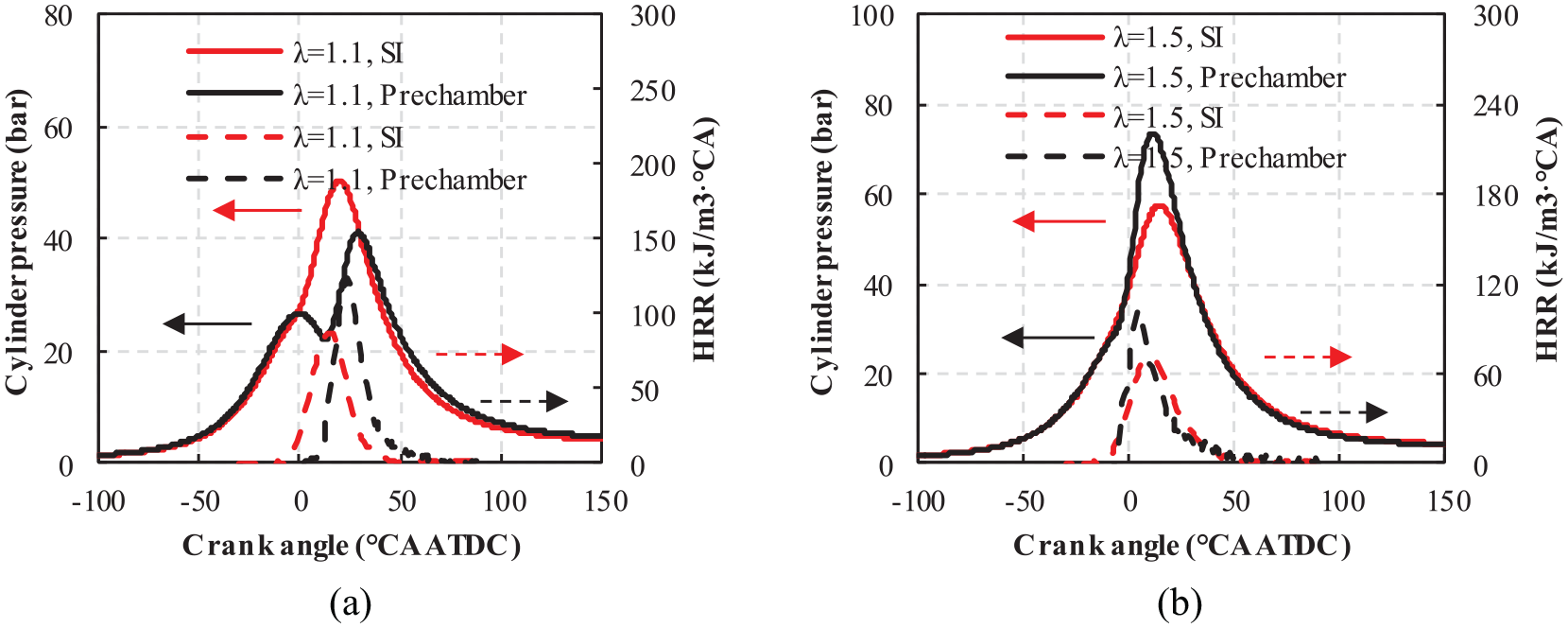
Variation of cylinder pressure and HHR: (a) lambda = 1.1 and (b) lambda = 1.5.
Figures 9 and 10 is the variation of emissions with lambda. The fast combustion of the pre-chamber jet ignition has greatly reduced the THC emission compared to conventional spark ignition, with a maximum reduction of 84%. Sufficient oxygen is benefit to the further oxidation of CO. However, with the further increase of air dilution, the flame propagation speed decreases, and the combustion cycle rate of variation (COV) increases, this results in an increase in combustion incompleteness and a slight increase in CO emissions. The rich mixture in the pre-chamber makes the CO emission larger than that of the spark ignition.

Variation of CO and THC emission with lambda (the solid line is CO and the dotted line is THC).

Variation of NOx and PN emission with lambda (the solid line is NOx and the dotted line is PN).
Pre-chamber jet ignition and spark ignition have the same NOx emission trend, and NOx emission reaches the maximum at lambda 1.1. The pre-chamber jet ignition expands the lean burn limit to lambda 2.0, which greatly reduces NOx emissions, with a maximum reduction of 78% compared to the conventional spark ignition.
The PN emission increases significantly when pre-chamber jet ignition is applied compared to spark ignition. On the one hand, the space in the pre-combustion chamber is small, and it is inevitable that the spray of the pre-chamber will wet the wall. On the other hand, the spray in the pre-chamber is in the compression stroke, the oil and gas mixing time is short, which lead to increased particulate emissions.
The effect of compression ratio on pre-chamber jet ignition
This section focuses on the effects of different compression ratios of 12.48 and 14.8 on combustion and emissions of pre-chamber jet ignition. The compression ratio was adjusted by adjusting the height of the cylinder head gasket.
Figures 11 to 15 are the variation of combustion parameters and emissions with lambda at different compression ratio. The high compression ratio 14.8 achieves 48.5% GITE, which is 1% higher than low compression ratio 12.48. The high compression ratio 14.8 extends the lean burn limit to 2.1, which is 0.1 greater than the low compression ratio 12.48. At the same time, after increasing the compression ratio, the ignition angle retard. When the AI10 is similar, the ignition delay AI10-IGN is shortened, with a maximum reduction of 8°CA.

Variation of GISFC and GITE with lambda at different compression ratio (the solid line is GISFC and the dotted line is GITE).

Variation of IGN and AI10 with lambda at different compression ratio (the solid line is IGN and the dotted line is AI10).

Variation of AI10-IGN and COV with lambda at different compression ratio (the solid line is AI10-IGN and the dotted line is COV).

Variation of AI50 and AI10-90 emission with lambda at different compression ratio (the solid line is AI50 and the dotted line is AI10-90).

Variation of THC and NOX emission with lambda at different compression ratio (the solid line is THC and the dotted line is NOX).
A high compression ratio leads to an increase in the tendency to knock, and this phenomenon is more pronounced when the lambda is low. When the lambda is less than 1.6, the combustion phasing AI50 is delayed. With the increase of lambda, the combustion temperature in the cylinder decreases and the knocking tendency decreases. At the same time, with the help of the active pre-chamber, the knocking can be further suppressed, and the AI50 can be kept at the optimal combustion phasing of 8°CA ATDC.
Compression ratio of 14.8 has a shorter combustion duration AI10-90. Compared with low compression ratio of 12.48, combustion duration of high compression ratio of 14.8 is shortened by 10°CA at lambda 2.
The two compression ratios have the same THC emission trend, as the lambda increases, THC rises slightly. When lambda is less than 1.6, the compression ratio of 14.8 has lower NOx emission. When lambda is greater than 1.6, the NOx emission of the two compression ratios are approximately the same. The compression ratio of 14.8 achieves the lowest NOx emission of 0.53 g/kWh at lambda 2.1. The reason is that NOx emissions are mainly affected by temperature, when lambda is small, the combustion phasing AI50 of high compression ratio retard, and the peak combustion temperature decreases. As the lambda increases, the AI50 of the two compression ratios reaches the optimal combustion phasing of 8°CA ATDC, the peak combustion temperature is approximately the same.
The effect of pre-chamber injection strategy
Pre-chamber jet flame technology can increase the combustion rate and improve the thermal efficiency in lean burn operation. Pre-chamber injection control strategy has a great influence on combustion and emissions, so it is of great significance to study the fuel injection strategy. The engine with spark plug ignition in this work achieves the maximum thermal efficiency at about lambda 1.7, therefore the pre-chamber injection duration and pressure are discussed at lambda 1.7.
The effect of pre-chamber injection pressure on pre-chamber jet ignition
When studying the injection pressure of the pre-chamber, the pre-chamber injection duration is kept at 300us. Figure 16 is the variation of AI10-IGN and COV with pre-chamber injection pressure. As the injection pressure increases, the amount of fuel injected in the pre-combustion chamber increases, which leads to an increase in the concentration of the combustible mixture around the spark plug, the ignition stability is enhanced, and the ignition delay is shortened.

Variation of AI10-IGN and COV with pre-chamber injection pressure.
COV is affected by ignition stability and combustion stability. As the injection pressure increases, the COV decreases. When the injection pressure is 10 MPa, the COV is less than 1%. The increase in injection pressure increases the pre-chamber jet ignition stability, which also improves the ignition stability of the main chamber.
Figure 17 is the variation of AI50 and AI10-90 with pre-chamber injection pressure. The combustion phasing AI50 is around 8°CA ATDC under different injection pressure. As the pre-chamber injection pressure increases, combustion phasing AI50 changes little and the combustion duration AI10-90 decreases.

Variation of AI50 and AI10-90 with pre-chamber injection pressure.
In the same combustion phase, as the combustion duration decreases, the heat dissipation loss decreases, and more fuel is burned near the top dead center, which reduces fuel consumption. Figure 18 is the variation of GISFC and GITE with pre-chamber injection pressure. The GITE increases with the increase of pre-chamber injection pressure, and the GISFC decreases with the increase of pre-chamber injection pressure.

Variation of GISFC and GITE with pre-chamber injection pressure.
Figure 19 is the variation of PN emission with pre-chamber injection pressure. As the pre-chamber injection pressure increases, PN emission increases. As the injection pressure increases, the amount of fuel injected in the pre-chamber will increase, and the mixture in the pre-chamber will be richer; the spray penetration also increases with the injection pressure increases, resulting in an increase in the amount of fuel that wets the wall of the pre-chamber.

Variation of PN emission with pre-chamber injection pressure.
The effect of pre-chamber injection duration on pre-chamber jet ignition
This section studies the influence of pre-chamber injection duration on combustion and emissions. The lambda of the test in this section is 1.7, and the injection pressure is 10 MPa.
Figure 20 is the variation of AI10-IGN and COV with pre-chamber injection duration. The ignition delay AI10-IGN first decreases and then increases with increasing injection duration. When the injection duration is 500 μs, AI10-IGN is the smallest. The main reason is that with the increase of the pre-chamber injection duration, the amount of fuel injected in the pre-chamber increases, and the concentration of combustible mixture around the spark plug increases, which is beneficial to the ignition, and the ignition delay is shortened; when the fuel injection duration is further increased, the mixture in the pre-chamber is too rich, resulting in poor ignition stability and increased ignition delay time.

Variation of AI10-IGN and COV with pre-chamber injection duration.
The ignition and combustion stability of the mixture in the pre-chamber have a greater impact on the COV of the main chamber. As the injection duration increases, the COV increases. When the pre-chamber injection duration increases to 800 μs, the COV exceeds 3%; when the injection duration is further increased, the mixture in the pre-chamber is too rich, resulting in a serious deterioration in the ignition stability.
Figure 21 is the variation of AI50 and AI10-90 with pre-chamber injection duration. With the increase of the injection duration, when the pre-chamber injection duration is less than 500 μs, the AI50 is near 8°CA ATDC, and the AI10-90 changes litter; but when the injection duration increases to 800 μs and further increased, the knocking trend becomes larger, AI50 retard, and the combustion duration becomes longer. The increase in injection duration of the pre-chamber leads to excessive enrichment of the mixture, which deteriorates the combustion in the pre-chamber, thereby reducing the combustion stability. At the same time, more high-temperature unburned fuel is injected into the main chamber to form a high-temperature enrichment zone, which increases the tendency of knocking.

Variation of AI50 and AI10-90 with pre-chamber injection duration.
Figure 22 is the variation of GISFC and GITE with pre-chamber injection duration. Figure 23 is the variation of PN emission with pre-chamber injection duration. As the pre-chamber injection duration increases, GISFC increases, GITE decreases, and PN emission increases. With the increase of fuel injection duration, the wetting wall fuel increases, and more fuel is unburned, which leads to the increase of fuel consumption and PN emission.
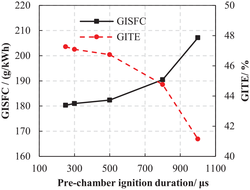
Variation of GISFC and GITE with pre-chamber injection duration.

Variation of PN emission with pre-chamber injection duration.
Conclusions
In this study, in order to further explore the potential of pre-chamber jet ignition technology for improving thermal efficiency and further understand the key parameters of injection control in active pre-chamber on combustion and emission. We conducted relevant experimental studies based on two different ignition technology. The conclusions obtained from the investigation are as follows:
Lean burn can effectively reduce engine fuel consumption and improve thermal efficiency. When equipped the conventional spark, lean burn limit is lambda 1.5.
At lean burn operation, active pre-chamber combined with high compression ratio can further improve engine combustion performance and fuel consumption. The active pre-chamber with compression ratio 14.8 can achieve 48.5% GITE, expand the lean burn limit to lambda 2.1, and reduce the minimum NOx emission to 0.53 g/kWh.
With the increase of pre-chamber injection pressure, the ignition stability increases, the COV decreases, the combustion duration decreases, and thermal efficiency increases.
With the increase of the pre-chamber injection duration, ignition delay first decreases and then increases, the COV increases. When the pulse width increases to 800 μs, COV is greater than 3%. If the pre-chamber injection duration further increase, the COV increases, the combustion phasing retard, and thermal efficiency decreases.
With the increase of fuel injection duration and pressure, the wetting wall fuel increases, which leads to the increase of PN emission.
According to the study, pre-chamber jet ignition technology has great potential to improve thermal efficiency compared with traditional spark ignition, at the same time, parameters in the pre-chamber have big impact on combustion and emissions of engine. In the future, we recommend that further studies should be carried out on the different structural designs of the pre-chamber, as they have significant impacts on the formation, movement and combustion of the mixture in the pre-chamber, and then affect the combustion of the main combustion chamber.
Footnotes
Appendix
Handling Editor: Chenhui Liang
Declaration of conflicting interests
The author(s) declared no potential conflicts of interest with respect to the research, authorship, and/or publication of this article.
Funding
The author(s) disclosed receipt of the following financial support for the research, authorship, and/or publication of this article: Zhejiang Provincial Natural Science Foundation of China (Project Number: LZY21E060002), “the Fundamental Research Funds for the Provincial Universities,” Zhejiang Institute of Economics and Trade (Grant Number: 22SBYB01), Key Projects of Natural Science Research in Colleges and Universities of Anhui Province (Project Number: KJ2020A0837, KJ2021A1210), Open Fund Project of Ma’anshan Engineering Technology Research Center of Advanced Design for Automotive Stamping Dies (Project Number: QMSG202101, QMSG202102).