
Abstract
Friction stir welding (FSW) factors significantly impact the welding characteristics of AA 8011 and similar alloys weld joints produced by FSW. The tool pin profiles influence joint characteristics, weld quality, and joint strength. This study used three tool pin profiles to create weld connections at three different tool rotation rates and various welding speeds. Design of experiments (DOE) was utilized to execute complete full factorial experiments. The welded joints’ mechanical characteristics were examined using hardness and tensile tests at room temperature. The average maximum hardness number was 38.28 HRB with the tapered tool at 1300 rpm spindle speed and welding speed of 20 mm/min at 5 kN unvarying axial force of the whole operation. The lowest hardness value was 30 HRB using a taper threaded pin profile tool, rotating at 1200 rpm and welding at 60 mm/min. When the taper pin profile tool was used at 1500 rpm, the highest tensile strength of the weld joint was achieved, which was the closest value of the parent material. At the same welding speed of 20 mm/min, the taper threaded pin tool at 1300 rpm produces the lowest tensile strength of 84.16 MPa, made utilizing a taper threaded pin tool.
Keywords
Introduction
Aluminum alloys have the most notable characteristics, including a high strength-to-weight ratio, higher hardness, better weldability, and enhanced anti-corrosion properties. which have made them highly sought after by industries such as shipbuilding, automotive, and aeronautics in recent years. Aluminum alloys based on magnesium offer superior strength-to-weight ratios, making them suitable for high-performance and high-durability maritime applications. 1 When it comes to extreme conditions like seawater and industrial chemical environments. The Base Material (BM), AA8011 alloy, stands out for its outstanding high resistance levels. Additionally, even after welding, it still has a high level of strength. Shipbuilding, vehicle bodies, railcars, mine skips, tip truck bodies, and pressure vessels are examples of common uses of these alloy materials. Despite the benefits described above and the widespread use of aluminum alloys in different assemblies, fusion welding is a difficult process because it may result in metallurgical defects, mechanical discontinuities, and a deterioration in the mechanical characteristics of the material. In addition to preventing fusion and decreasing the influence of temperature on material characteristics, solid-state welding provides the additional advantage of producing higher-quality welds overall. 2 The ability to design and construct components with qualities adapted to regionally variable environmental conditions is enabled by aluminum joining. On the other hand, differences in thermal properties, metallurgical compatibility, and mutual solubility considerably affect similar joining. These issues have highlighted the significance of evaluating the use of solid-state techniques for aluminum components, such as Friction Stir Welding (FSW). In this technique is a simple and effective process of connecting aluminum and its alloys. It was invented in 1991 at the TWI institute by employing the Non-consumable rotating tool and is depicted in Figure 1 is a fruitful solid-state joining procedure for similar and dissimilar alloys. This method gradually developed in advanced technologies for different material joining processes. The FSW Spinning tool to build frictional heat between two base metal plates translates mechanical energy into heat energy without using electrical energy to form the weld material under different axial load conditions. This method is frequently utilized in the field of various applications. The FSW process produces enormous joint quality in the joining of Non-ferrous alloys.2,3 Aluminum alloys are one of the most importantly lightweight structural materials and are well known for their strength characteristics. It has recently alternated between steel alloys and copper materials in different structural applications. Aluminum alloys are extensively used in ship buildings, aerospace, and automotive industries of these materials. It is primarily due to their extraordinary qualities, including high strength in a low-density material, excellent heat conductivity, corrosion resistance, good castability, high machinability, and non-magnetic features. In recent years aluminum alloys have been increasing rapidly in different fields, and it has excellent material properties. It has recently alternated between steel alloys and copper materials in different structural applications. The ship buildings, aerospace, and automotive industries use these materials as well. 4 The influence of welding settings on the mechanical characteristics and microstructure of the AA5086 aluminum plate was studied. The hardness and grain size of the welding zone changed according to the rotation speed and feed rate. The impact of welding settings on the hardness of commercial magnesium and aluminum alloys was investigated in welding joints. In the stirred zone, the hardness was high at weld joints, whereas the welding process affected the areas outside the stirrer zone. 5 After investigating the fatigue characteristics of the aluminum alloys Al1120, it was observed that the fatigue performance of welds of identical aluminum alloys at low-stress ranges was inferior to weld joints of different aluminum alloys. 6 The mechanical properties were determined by raising the rotation rate of the tool and reducing the welding speed while studying the influence and microstructure of the welding parameters. The effects of various rotation speeds on weld quality in Ti-6Al-4 V/AA6061 alloy welding joints are explored. As the speed of rotation increases, heat is created on the surface of friction at the interface, resulting in dynamic recrystallization. These researchers are attempting to determine the effect of various stirring pin geometries on the corrosion behavior of the alloy under investigation in this study. It was discovered that the square pin geometry was the most corrosion-resistant of the three options tested. The pin shape causes vibration stirring, and the dynamic-to-static ratio is high. A limitation of this material is that it is difficult to weld or combine due to its wide variety of melting points. 7

(a) Photographic view of FSW machine and (b) schematic view of FSW principle.
As a result, welding flaws such as internal porosity fractures in welded joints are decreased since the joining technique does not include the melting of the parent material. During the material joining process, there are few processing conditions to control, such as FSW revolving tool speed, pin profiles, and feed rate, while in the conventional joining process, numerous aspects must be examined, including the current level, the arc gap, the purging, and the trip speed. 8 Thus, friction stir welding is an energy-efficient and environmentally benign way of joining. The FSW schematic process diagram and principle are shown in Figure 1.
As stated, FSW is the attractive fabrication technique of aluminum alloys in solid-state conditions. However, in any method, there will always be minimum constraints, losses, and defects. 9 The controlled FSW parameters will produce various results on the joint alloys in terms of solidification of metals and strength basis.
In this research, the influence of FSW tool pin profiles on the mechanical characteristics of AA 8011 similar alloys was successfully examined.
The present work analyzes a viable approach for obtaining the appropriate FSW parameters for welding the aluminum alloy AA8011-with a high carbon high chromium-H13 steel tool under a variety of carrying conditions. It was discovered through the study findings that the control variables had a variety of effects on the response variable. When it comes to rotating tool speed, the welding speed, and the profile of the tool pins, these are the factors that have the greatest influence. DOE techniques simplify the process of regulating the limitless possibilities of design parameter settings that can be achieved through testing. After the revolving rate of the tool, the tool traverse rate is the next most significant component that contributes to all of the parameters. On the other hand, the pin profile of the tool is the least significant element that contributed.
Although the use of aluminum alloy plates in the industry has increased steadily in recent years, few research has been done on the microstructural characteristics, and mechanical properties of the weld joint that occurs during the welding process were evaluated. Variable tool pin profiles, rotational tool speed, and welding feed rates were observed to create variances in microstructural characteristics and mechanical properties, such as distribution of hardness and tensile property of the joint, which were investigated in this work to make a complete analysis of mechanical properties and microstructure analysis in friction stir welding single-sided butt welding of AA8011 aluminum alloys with a thickness of 5 mm.
This study focuses on welded joint material qualities such as tensile strength and hardness. Numerous studies have been conducted to determine the impact of tool geometry on welded joint strength. The effects of three FSW parameters, such as rotating tool speed, welding speed, and pin profiles, have been studied on the mechanical behavior of the weld joint. The current study was utilized to explain the qualities of welded joints, such as hardness, tensile and yield strength, and the impacts of FSW on these parameters. The parametric combinations and their factors were studied through the L27 orthogonal array. The optimal solution of hardness, tensile and yield strength with respect to the FSW process parameters have been performed through the Taguchi approach.
There has been much research into the effect of FSW on Al alloy joints, which has been published. A number of typical FSW process settings were used by the researchers to successfully construct weld joints made of the AA8011 alloy. The ideal FSW process conditions for AA8011 alloys were discovered in accordance with earlier research, and they were used in the successful fabrication of weld joints of AA8011 alloys. The best processing conditions were recommended based on the process parameters used to obtain microstructures and mechanical properties, which were supported by the experimental data. In this current investigation, the different process factors, such as the rotating speed, travel speed, and tool pin profiles, had a significant impact on the microstructural characteristics and mechanical properties of weld joints. It is essential to determine the best process parameters to increase welding quality and eliminate weld joint faults.
Experimental methodology
Materials
A base material (BM) AA 8011 Aluminum alloy was used in this inquiry. The AA8011 aluminum alloy plates have the required dimensions of 100 mm ×50 mm ×5 mm for friction stir weld connections. The aluminum alloy plates were cut to the correct dimensions (length, breadth, and thickness) using a power cutting machine, and then milled to avoid sharp edges on the specimen. Using manual top clamps, the base material AA 8011 alloy plates were fixed in the weld position. As indicated in Figure 2(a), the tool is plunged and moves high and rigidly in the direction of the weld position. The selection of tool materials is an art form in the FSW process. When selecting FSW tool material, two significant considerations are the wear of the tool material and the quality of the joint. Due to the possibility of influencing heat production during the material joining process, it is conceivable that the FSW tool will not affect weld quality.10,11 In this work, the FSW tool was successfully fabricated with required dimensions by using Computer Numerical Control (CNC) machine and checking the dimensions were used profile projector and check wear loss of the tool pin via the optical microscope image. The tool material used in this experiment has a high carbon and a high chromium content tool steel (HCHCR). There are three types of pin geometries used in this research: like taper thread, taper cylindrical, and straight cylindrical. Photographs of the FSW tool with each of these pin geometries are shown in Figure 2(b). Tables 1 and 2 indicate the chemical composition and the mechanical behaviors of the two materials, respectively.

(a) FSW joint arrangement set up and (b) different FSW tool pin profiles.
Chemical composition of AA8011 alloy (weight%).

Mechanical characteristics of AA8011 alloy.

Methods
The Friction Stir Welding setup for this experiment was created using a vertical milling machine. The machine’s spindle is turned according to predetermined settings, and the tool is begun to dive between two plates for 5 mm (plate thickness). The tool spins for up to 30 s at the specimen’s starting position to produce heat in the material. The spinning spindle began to move and agitate the material clockwise, from +y to –y, to facilitate welding between two work parts. The pieces were linked (welded) along the –y axis for 85 mm from the start. The tool was allowed to stay 15 s at the furthest point of the alloy plates before being withdrawn. After the procedure, the remaining welding splash is removed by using a grinding process.
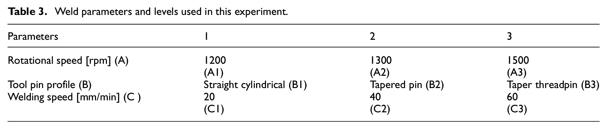
Analysis of micro-hardness, macrostructure, and microstructure is used to investigate the effects of processing parameters such as tool transverse speed, rotational speed, and tool pin profile on the weld properties of aluminum alloys. During the stirring process, heat is generated by the friction of the tool shoulder surface against the base material (BM) and by the plastic deformation of the base material (BM). The heat flux softens the material locally without melting it, preventing unwanted melting-related metallurgical flaws. Stirring by friction welding joints was achieved with the help of the FSW tool and the design of experiments with full factorial design. Before carrying out the final tests, a number of pre-experiments (trial runs) were carried out with a variety of various parameters to test the hypothesis. These tests were carried out to determine the working range and levels. Using a tensile test of the butt joints and visual inspection of the cross-section of the welded junction, it was determined that the final operating levels were satisfactory (must be free of any visual defects). Table 3 reveals the selected weld parameters as well as the range. Table 4 shows the design matrix conferring Taguchi L27. As specified by ASTM E8-04, specimen samples are subjected to tensile testing. Axial force control was used to make the joints, with the tool penetration depth varying to maintain the applied tool force constant. A set of process characteristics, including axial force, rotational speed (A), tool pin profile (B), and welding speed (C), were also detected for each weld. A weld joint’s strength and quality are directly proportional to the parameters used in the welding process. In comparison to other aluminum alloys, those in the 8XXX family have higher strength. This research demonstrated that the welding parameters evaluated had a significant impact on the tensile and hardness characteristics of the different aluminum alloys weld. As a result, the welding technique for aluminum’s 8XXX series has the potential to expand its range of applications. According to this article, the best FSW condition for getting the maximum UTS value for AA 8011 comparable weld joints is discussed in detail. The optimum welding conditions are determined based on three input constraints, which are the rotational speed of the tool, the welding speed, and the pin profiles of the welding tool. The results of microstructural and microhardness analyses of the welds obtained under the optimal circumstances for friction stir welded joints are also presented in this study.
Weld parameters and levels used in this experiment.
DOE Matrix with factors and levels.
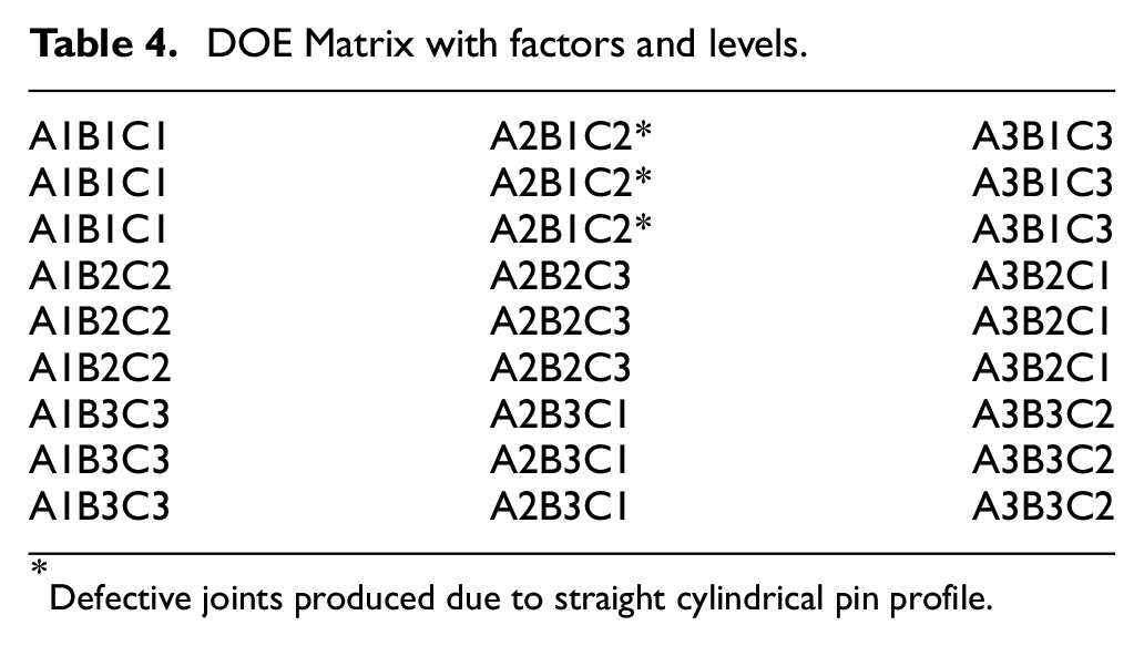
Defective joints produced due to straight cylindrical pin profile.
Weld joint appearance
Figure 3 illustrates, that the weld morphology exhibits a regular surface with semicircular bands spaced evenly apart and no faults visible upon visual inspection. Welds with no evident structural defects at the weld surface or weld root were all considered to have outstanding appearances. The weld samples after being done by FSW illustrate Figure 3(a) to (c) depict the top view of a weld joint surface formed at speeds of 1200, 1300, and 1500 rpm, respectively. All of the welds had a consistent bead or a reduced flash, as well as a slightly rough surface. Although the process parameters used were varied, the combinations of parameters used inside the weldability window can be attributed to the similar quality of beads. There are elliptical and basin-shaped nuggets with an onion-ring structure in the predominant stir zone discovered in the similar FSW of the alloys.12,13 Sample A produced better mechanical properties when compared to sample B; however, the lower rotational speed resulted in a lower amount of energy being used to promote plasticization in the latter. The choice of tool material selection and design has a significant impact on the performance of tools and the quality of weld joints produced in the FSW process. In this study, three different tool pin profiles were used to join aluminum plates that were 5 mm thick. The straight cylindrical tool pin profile, the tapered cylindrical tool pin profile, and the tapered threaded tool pin profile were all used. The reduced coefficient of friction between the weld metals in HCHCr oil-hardened tools results in smooth weld surfaces.

Weld joint appearance at different tool rotational speeds : (a) at 1200 rpm, (b) at 1300 rpm and (c) at 1500 rpm.
According to Mishra and Ma, 14 the tool wear is less severe in the FSW of aluminum alloys than in other alloys. As a result, tooling materials such as HCHCr tool steels can be employed in this process. The friction heat developed in the tool and, consequently, the temperatures reached are influenced by the material properties of the tool. In order to achieve specific qualities in the final joint, such properties as heat conductivity are important in the tool material selection. The tool’s thermal stresses are proportional to the material’s coefficient of thermal expansion. The hardness, ductility, and reactivity of the work materials may also have an impact on the selection of tool materials.
In accordance with Akos and Imre, 15 Aluminum, copper and magnesium alloys are among the most frequent materials for welding and processing, and in these procedures, HCHCr tool steel is one of the most regularly used tool materials. These materials allow the welding of tool steel up to a thickness of 50 mm. High-temperature thermal fatigue resistance is provided by the tool materials used in this sort of application, which is easily available and have excellent machinability. Tool steels have a strong resistance to damage from abrasion and distortion in welding of aluminum alloys and other moderate melting temperature materials, but stainless steels have a lower resistance. Tool steels can be utilized in a variety of applications, like weld lapped or butt joints with both identical and dissimilar welds. As a result of the butt joint arrangement, stronger base metals are positioned on the advancing side (AS), and softer materials are placed on the retreating side (RS). To facilitate welding, the tool is equipped with a slight offset from the butt interface in the direction of the softer material.
High carbon, high chromium (HCHCr) tool steel has one of the highest wear resistance ratings of all the tool steel grades tested to date. A combination of stress and abrasion resistance with red hardness distinguishes this material. Because of its high hardness and chromium content (5%), it is commonly used in aerospace applications. Chromium stainless steel (SS) is a type of steel that has an extremely high corrosion resistance capability. Each alloy that is utilized in the production of certain tool steel makes a unique contribution to the features of the tool steel that is produced.
For recent advancements in manufacturing sectors, an investigation of the effects of tool pin performance on tensile strength and microstructural changes at weld joints has been carried out. HCHCr Tool steel materials are extensively used in the FSW tool for joining aluminum alloys of the 8XXX-series, resulting in improved mechanical properties at weld-joint regions.
Optimized FSW process parameters
The revolving speed of the FSW tool, the welding rate, and the pin shapes were all factors in determining the strength and quality of the weld. Different experimental works have been completed by many researchers with several combinations of alloys.16,17 The primary elements like tool rotational speed, welding speed, and tool pin profile that have a bigger influence on the welding process by FSW technique have been discovered based on the literature review. Using the best process parameter values provided in Tables 5 and 6, the FSW of AA 8011 aluminum alloy plates were successfully welded and reached the tensile strength and hardness levels at their best. After conducting a thorough literature review, the FSW process parameters such as tool revolving rate, tool traverse rate, and pin profile of the FSW tool were discovered. These chosen FSW parameters will result in a wide range of weld joint qualities.
Optimized FSW process parameters used.

Optimized mechanical properties obtained for various FSW tool pin profiles.

Testing details of the weld plates
It was determined that the tensile characteristics of friction stir–welded AA8011 aluminum plates were assessed utilizing universal testing equipment that could handle 40 tons of weight. In order to do the test, the crosshead speed was set at 1.5 mm/min. A test was conducted on specimens obtained from the material joining process while FSW of AA8011 aluminum alloy was in different parameter levels. The samples for tensile test samples are illustrated in Figure 4.

Photographic view of after tensile test specimens.
Results and discussion
Effect of tool pin profile, welding speed, and tool rotational speed on the hardness
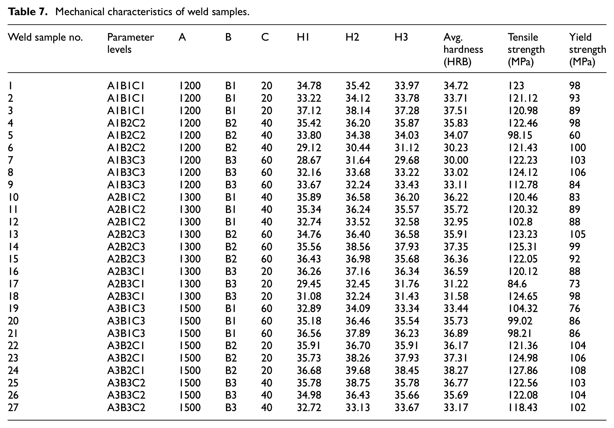
All weld specimens were subjected to a hardness test, performed at three different positions along the weld line route. The ASTM standard, Rockwell B scale with 100 kg force, was used for this test. At different rotating speeds and transfer speeds, 27 specimens were successfully welded. Pin profiles were also successfully constructed and tested. The hardness of the sample was evaluated at five different weld positions in the sample, and an average value was computed. 18 The distance between two points is roughly 15 mm along the length of the bead, measured from one to the other. Tensile, hardness, average HRB, and yield strength are all assessed along the weld line and are the results of the tests. The values are listed in Table 7. The microhardness values of AA8011 FSW weld joints were determined by considering the parameters of varying rotational speeds, feed rates, and stirrer pins profiles for the material joining process. The measurements were taken from the connecting line to the base material (BM) and from the BM to the joining line, and back again. The hardness measurements are depicted in Figure 5. After analyzing all of the joined specimens utilizing three different tool pin profiles, the weld zones (HAZ, TMAZ, and DCZ) of all specimens were welded using three different tool pin profiles with varying hardness readings. The hardness values of BM were close to the fundamental hardness values of aluminum alloys. Because the pins stirred via the direction of rotation, the samples’ weld centers had unusually high hardness. As the grain size of the alloys was lowered, plastic deformation and extrusion induced hardening. It was discovered that when a taper cylindrical stirrer pin was used rather than a straight cylindrical stirrer pin and a threaded pin profile, the hardness measurements at the weld center of the connected samples were slightly higher, demonstrating the difference in the shape of the stirrer pins used in this study. Using helical taper cylindrical grooves on the surface of the taper cylindrical stirrer pin, the material in front of it was swirled rearward. The taper pin stirrer pushed the material on the front of the triangle stirrer backward relative to the direction of the welding current, depending on the feed rate. Stirrer pin mechanisms have an effect on the measured hardness of welded joints.18,19
Mechanical characteristics of weld samples.

Variation of avg. hardness with FSW weld parameters.
With a closer look at the data in Table 7, it can be seen that the maximum HRB values are found at point 2, while the lowest hardness values are found at point 1. 20 The dwell time of 6 s was kept at Point 1, and the tool is rotating at the required speed without advancing to the next point. As a result of the increased frictional forces generated by the friction stir welding process, more heat will be generated at Point 2 as compared to Point 1 at the end of the process. Grain refining occurs as a result of the development of high temperatures at point 2, and the hardness values have improved from point 1 to point 2. The high temperature will cause equiaxed grains to form and the hardness value to rise, resulting in the solidification of the whole material. Two elements that determine hardness values in most instances are the amount of solid-solution strengthening present, as well as the size and distribution of grains. The hardness value in the stir zone is higher than in the rest of the sample because of the obvious fine equiaxed grains generated as a result of dynamic recrystallization. Furthermore, a graph of the average hardness of each weld parameter is drawn on tested values in Figure 5, which is separate from the rest of the inquiry. Hardness values are sometimes given in terms of maximum and lowest average. Meanwhile, the point 2 parameter of A3 B2 C1 (1500 rpm, taper pin profile, 20 mm/min) yields the maximum hardness values (38.27 HRB), found at point 2 of the A3 B2 C1 parameter set. As a result of adequate heat generation and material movement required for sufficient softening and mixing of the deformed base material, which results in refined grains. However, the point 1 parameter of A1 B3 C1 yields the lowest hardness value of 30.0 HRB at 1200 rpm and 60 mm/min for a taper threaded pin. Upon increasing rotational speed while decreasing transverse speed, it was discovered that the specimen’s hardness increased maximum when rotating at high speed. As rotational speed increased past a certain point, the hardness value of the weld joints decreased as a result of the reduction in hardness value. The analysis of variance (ANOVA) was successfully completed after a thorough investigation of the relationships between the three factors. Finally, the experimental results indicate that a variety of tool pin profiles, rotating tool speed, and welding speed all influence the mechanical properties of weld joints. Additionally, the analysis results (Table 5) demonstrate that the combination of revolving tool rate and the shape of the tool pin has a more substantial influence on the outcomes than the groups of welding speed and rotational speed, as well as the groups of tool pin profile and welding speed, which have a minor effect on the outcomes.
Effects of rotational speed, tool pin profile, and welding speed on tensile strength
Tensile strength testing was performed on the weldment specimen in accordance with the ASTM-E8-04 specification. A total of 27 specimens were fabricated and evaluated, each of which was welded at a different rotational speed, transfer speed, and pin profile. It is demonstrated in Figure 6 that the tensile strength of all-welded specimens may be influenced by the rotational tool speed, as well as pin profile and traverse speed, on tensile strength. All of the weld joints are shown side by side in Figure 7 to demonstrate the wide range of mechanical qualities. To achieve maximum tensile strength on all welded connections, the tool speed, welding speed, and pin profile are all critical aspects to consider. The tool pin profile is responsible for swirling and mixing the material around the spinning tool during FSW. A substantial improvement in specimen tensile strength was found when welding was carried out at 20 mm/min transfer speed. Weld zone temperature uniformity offered by the tool may have contributed to the increase in tensile strength. The perfect heat distribution found in the welded zone, caused at higher rotational speeds, is responsible for the impact when the rotational speed increases beyond 1200 rpm. The enhanced tensile strength value of 127.3 MPa was achieved at rotational and transfer rates of 1500 rpm and 20 mm/min, respectively, due to the material being agitated more effectively with taper pin profiles. When both feed rate and rotating speed were raised, the tensile strength of welding junctions was lowered. The amount of material transported every revolution and extruded backwards is increased due to efficient stirring. It also increased the amount of plastic deformation that occurred. Because of this, the size of the grains in the welded aluminum alloy joints was decreased, while the mechanical qualities of the joints were strengthened.21,22 When it came time to conduct the tensile tests, the results revealed that the tapered pin was important in ensuring that the material was thoroughly stirred throughout the process. According to the FSW acquired findings, the highest tensile strength value was created for the taper pin profile when the rotating tool speed was high, and the lowest was produced when the welding speed was fast. In addition, the straight cylindrical pin profile with a medium spindle speed of 1300 rpm and the lowest welding speed of 20 mm/min produces the lowest tensile strength value possible for straight cylindrical pin profiles.
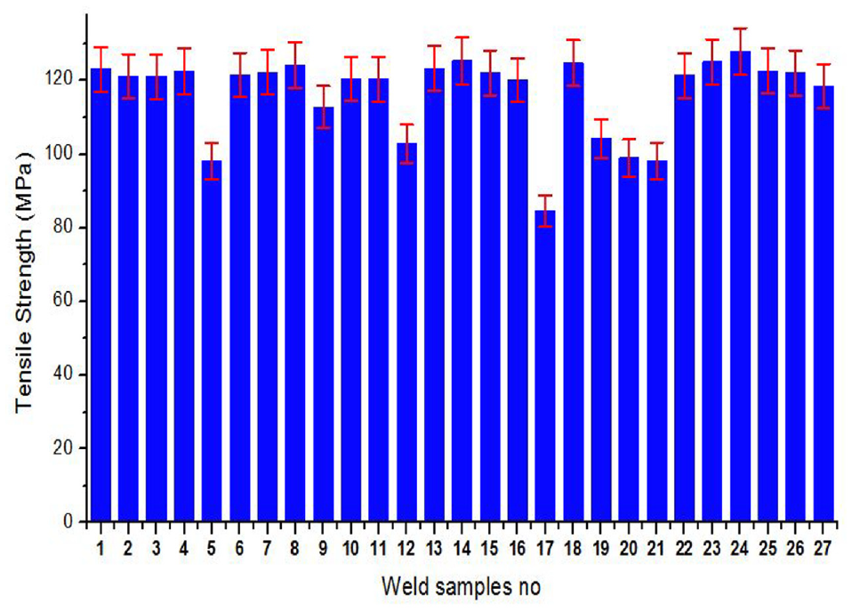
Variation of tensile strength on FSW weld samples with process parameters.

Variation of tensile strength, avg. hardness and yield strength with FSW weld parameters.
Macrostructure analysis
Figure 8 illustrates the macrostructure of friction stir welded AA801 1aluminum alloys with a taper cylindrical stirrer pin using various FSW process factors. It is shown how the macrostructure of the different zones achieved at the optimal parameter appears. In the advancing side (AS) and retreating side (RS), three unique zones are detected during FSW. These zones are referred to as the stir zone (SZ), the thermo-mechanically affected zone (TMAZ), and the heat-affected zone (HAZ). The macrostructure of the joints has a significant impact on the mechanical properties of the joints. Both the advancing and retreating sides of AA8011 aluminum alloy are located during the entire joint-making process. During the joint fabrication process using three distinct tool pin profiles, the welds were joined at three different speeds of 1200, 1300, and 1500 rpm, then at three different welding rates of 20, 30, and 40 mm/min, respectively. Due to the differences in their material characteristics, melting temperatures, and deformation rates caused by the differences in the FSW process parameters, the identical welds display distinct material flow and mechanical intermixing at their joint interfaces compared to one another. Thus, the four unique zones like parent material, heat impacted zone, thermo-mechanical affected zone, and stir zone are less likely to be found in the FSW of comparable alloys when compared to other materials. Due to the low frictional heat production, a discontinuous flow of plasticized material between the advancing side and the retreating side is seen at this junction. 23 The specified process parameters result in only a tiny amount of frictional heat being created at 1200 rpm spindle speed and 20 mm/min welding speed with a taper cylindrical tool pin profile, as depicted in Figure 8(a). As a consequence, unsatisfactory weld joints such as tunnels and wormholes are produced. Due to insufficient heat flow in the center of the weld, the stirring of the comparable alloys at the center of the weld may not be sufficient heat to achieve the necessary mixing to achieve the required mixing. The tool’s rotating speed of 1300 rpm and 20 mm/min welding speed cause intermediate material mixing in the stir zone. At these interfaces, visible interpenetrating features (IPFs) occur due to limited mixing between comparable alloys, resulting in greater material flow without weld flaws and intermixing between the two alloys, marginally improving joint characteristics as shown in Figure 8(b). According to the findings in Figure 8(c), the joint made at a tool speed of 1500 rpm and a 20 mm/min welding speed had no weld defects. It has been feasible to determine the optimal process conditions for creating frictional heat during the joint fabrication process and surpassing ideal material flow stress to produce sound weld joints by selecting process parameters.

(a–c) Macrostructures of the FSW joints of AA 8011 alloys at different process parameters.
Microstructural analysis
Figure 9 shows the optical microstructures of the AA8011 aluminum alloys’ base material and nugget region of the FSW samples, which were used to evaluate the sample’s optical microstructure. Figure 9(a) demonstrates the coarse grain structure of the base material, which is not evenly distributed. In comparison to welded material, the FSW samples exhibited a homogeneous fine grain structure. At the nugget zone, a superior microstructure with more uniform grains was created using a taper cylindrical tool at a tool rotational speed of 1500 rpm and a 20 mm/min welding speed. Because of this, FSW with a taper cylindrical tool produces better mechanical characteristics than other parameters. Due to grain growth occurring throughout the manufacturing process, the joint formed by a straight cylindrical tool has a uniform microstructure with huge grains, which results in poor mechanical qualities. Figure 9(b) illustrates the microstructural formation of a similar Aluminum joint using a taper cylindrical tool at a tool speed of 1200 rpm and a welding speed of 20 mm/min. The grain size was larger than the grain sizes of base metals AA8011 alloy, owing to inadequate dynamic recrystallization during friction stirring, which resulted in reduced frictional heat generation. Weld nugget region grain size distribution is poor due to material vortex movement during the welding process, and an onion ring formation with concentric circles occurs along the weld nugget region due to low tool rational speed and welding speed as a result of poor material mixing during the joint fabrication process as a result of the low tool rational speed and welding speed.24,25

(a–f) Microstructures of the FSW weld joints.
A taper cylindrical pin profiled tool with a rotating speed of 1300 rpm and a welding speed of 20 mm/min is shown in Figure 9(c), representing the weld joint’s interface area. It clearly depicts the tool shoulder affected area toward the retreating side (RS) and the microstructure of the interface zone, which is easily discernible in this image. The grains suffered substantial damage in the TMAZ zone, which was next to the stir region. Dynamically recrystallized equiaxed grains were observed on the RS side of the interface zone, whereas grain particles were poorly distributed on the AS side due to a lack of frictional heat generation caused by the tool rotational speed and welding speed, resulting in grain size variation that had a negligible effect on the mechanical properties of the weld joint. Figure 9(d) resulted in the microstructure in the zone in the middle of the interface. The grain sizes in the TMAZ region developed as the distance between the stir zone and the HAZ increased. The grains are originally deformed in the nugget region, as shown in this region. As a result of the frictional heat generated in the shoulder affected zone, the grain sizes in this region are more variable than those in the uninfluenced shoulder region. 26
Figure 9(e) shows optimal material flow in the pin-influenced zone of a weld joint made at 1500 rpm tool rotation and 20 mm/min welding speed. The material deformed upward toward the stir zone reveals that the grain flow has been properly blended with both welded components. It displays the nugget zone’s center and the shoulder-influenced region, where both materials contribute to the welded area (Figure 9(f)). To make the plasticized material flow around the pin, it must be correctly combined and swirled. Material is extruded from the front to the back of the pin as the tool moves forward. Material flow and friction heat are employed in friction stir welding to join materials at the weld contact. In FSW, the tool shoulder generates 80% of the heat, while the pin generates 20%. The pin profile also affects material flow. A number of studies concluded that the amount of heat supplied to the stir zone influences fault generation and location. A high tool speed combined with a low welding speed caused by the pinning effect was used to reduce the grain size in identical aluminum AA8011 weld joints. This resulted in the grain size in identical aluminum AA8011 weld joints being reduced. Furthermore, enhanced welding parameters such as high tool rotating speed, low welding speed, and tapered pin-shaped tool changing all contribute to the reduction of grain formation.27,28 This modification in the welding parameters, on the other hand, resulted in the dissolving of the strengthening intermetallic particles in AA8011 and the precipitation of intermetallic particles at grain boundaries. The benefits of the tool’s high rotating speed and low welding speed result in a decrease in grain size and an increase in the dispersion of grain particles in the nugget zone, both of which are advantageous. High heat input causes microstructure deterioration in AA8011 weld joints, and the high rotating speed of the tool and the low welding speed of the tool both contribute to this degradation. Microstructural research has shown that the optimal welding conditions are also conducive to the formation of grains and microstructures in the welded materials. The pin profiles have varying effects on material flow, defect location, and defect formation, despite the heat input range remaining the same. The shape of the tool pin profile affects stirring and flow direction more than other process factors like the ratio of shoulder diameter to plate thickness (D/T ratio) and shoulder diameter to pin diameter (D/d ratio).
SEM analysis
Figure 10(a) to (c) shows the SEM (Scanning Electron Microscope) images of defect-free weld joint produced by taper cylindrical pin profiled tool at a rotational welding speed of 1500 rpm and 20 mm/min, respectively. Figure 10(a) illustrates the base materials SEM image; it shows the irregular grain particles present in base material with a grain size of 40 μm. Figure 10(b) shows the SEM micro pattern of the nugget zone of the quality sound weld joints. The micropatterns depicts there is a significant distribution in grains in the stir zones, which is consistent with this observation. Fine grains that have been dynamically recrystallized and equiaxed are experienced in SZ. Because of frictional heating and plastic deformation generated by the rubbing and stirring of the tool with the BM, the fineness of the grains is a result of dynamic recrystallization. Because of the heat input and deformation in the SZ, grains are fine and recrystallized as those in the SZ. In TMAZ, both in AS and RS, it is possible to observe highly deformed grains of regular size. Only welding cycles and no deformation are used in the HAZ. The presence of deformed finer grains slanting in the direction of the rolled BM is clearly seen in this zone of the grain distribution. Figure 10(c) depicts the elemental mapping of the grain particles evenly distributed in the stir zone. The aluminum gains are evenly and uniformly dispersed in the weld nugget zone, which leads to the properly mixing of two base materials during the joining process. The better mechanical properties were attained, Due to proper frictional heat generation with the help of optimized process parameters. The defect-free sound weld joints were obtained at a tool rotational speed of 1500 rpm and a welding speed of 20 mm/min.

(a) SEM image of base material, (b) nugget zone, and (c) elemental mapping of the defect-free weld joint.
Fracture analysis
Figure 11(a) and (b) show SEM images of fracture tensile specimens of the weld joints collected at different magnifications with a taper cylindrical tool pin profile at a rotating speed of 1500 rpm and welding speed of 20 mm/min, respectively. Those weld connections with a smooth taper pin profile have dimples that are densely packed. A number of small dimples and fractures may be seen on the fracture surface in this tool profile. 29 Size, form, strain hardening in the stir zone and dispersion of precipitates are all critical characteristics for similar welded junctions. The lowest tensile strength of 84.16 MPa was reached in the stir zone using a taper threaded pin profiled tool with a rotating speed of 1300 rpm and a welding speed of 20 mm/min, which was used in conjunction with a taper threaded pin profiled tool. The effect of the tool shape, as well as these process parameters, resulted in the lowest possible tensile strength when the least amount of heat was applied. The increasing side tunnel faults are the failure point during loading. The taper pin profile has the highest tensile strength. The presence of Mg precipitates in the stir zone increased AA8011. When the pin stirs the base material, it generates heat when it comes into contact with the tool and the BM, which results from friction and plastic deformation. Local softening occurs without melting, thereby avoiding undesired metallurgical faults in the process from being formed as a consequence of the heating. The taper cylindrical pin partly dissolves the precipitate in the stirring zone. Due to dynamic recrystallization in the stir zone, fine equiaxed grains are observed. In terms of grain boundary formation, the availability of precipitates is more essential than strain hardening magnitude. Due to this, the taper cylindrical pin profile is stronger than other pin profiles. Taper threaded and straight cylindrical tool pin geometries have less ductility than welded materials. The mechanical qualities of defect-free weld connections generated by the taper pin profiled tool were superior to those produced by conventional tool pin profiles.1,2,30–32 Figure 11(c) depicts the EDAX report’s confirmation that the nugget zone of the welded specimen contained a significant amount of Aluminum, Magnesium, and other elements, which resulted in higher tensile strength when the process parameters for the study were optimized for the material under consideration.

(a–c) SEM photographs of fracture tensile specimens with EDAX report.
Conclusions
Aluminum alloys have been extensively employed in the aviation and shipbuilding sectors throughout history. Welding is one of the most often used joining methods in those sectors. When compared to other aluminum alloys, the strength of the AA 8XXX series aluminum is better. The welding parameter investigated in this experiment was shown to substantially affect the tensile and hardness characteristics of different aluminum alloys welded together. Consequently, the welding procedure for aluminum alloys AA8XXX has the potential to broaden their range of uses. In addition to AA8XXX series aluminum, friction stir welding on additional aluminum alloy series such as AA9XXX series aluminum will increase the strength of the goods by a factor of more than 1. Consequently, other researchers will have access as a result of this.
FSW was effectively used to complete the weld joints in a variety of tool pin profiles, including taper cylindrical, straight cylindrical, and taper thread. The taper pin profiling tool was used to provide the huge mechanical features examined in this study. The weld joints have higher tensile and hardness values than the other two FSW tool pin profiles under the same operating conditions. Similarly, two more pin profiles were generated related to the taper pin profile tool. It is determined that the smoothness of the friction stir weld joints present in the alloy components contributes to the reduction of strength and precipitates during the connecting of two materials, resulting in a deterioration of the mechanical characteristics. Friction stir welding settings such as tool rotational speed of 1200, 1300, and 1500 rpm at welding speeds of 20, 40, and 60 mm/min at a constant axial force of 5 kN are employed in this experiment.
The following important conclusions were made in this research article.
After the ANOVA was conducted, the significant parameters tended to degrade the characteristics of the weld joints. The parameters are the rotating speed of the tool, the tool pin, the welding speed, and the combination of tool profiles.
It is found that the FSW zone may provide the maximum average hardness value when manufactured at 1500 rpm with a taper pin profile and welding speed of 20 mm/min. Furthermore, the lowest average hardness value is achieved from the FSW zone at 1200 rpm and 60 mm/min, 38.27 HRB and 30.0 HRB, respectively, using a taper threaded pin profile.
Maximum tool rotating speed and lowest tool traveling speed is used to generate the highest hardness value possible.
The highest tensile strength value possible is achieved at 1500 rpm, taper pin profile, and 20 mm/min welding speed, resulting in 108 MPa of yield strength value.
A taper pin profile and welding speed of 20 mm/min resulted in the greatest tensile strength in the FSW zone, whereas a taper threaded pin profile and tool traverse speed of 20 mm/min produced the lowest. More uniform precipitates, circular onion rings, and a smaller grain size result in enhanced weld joint performance when the taper pin-shaped tool is used.
The tensile strength values of the FSW joint are 127.86 MPa at the maximum and 84.6 MPa at the lowest, respectively.
Weld joints’ tensile strength and hardness value were mostly influenced by the rotating speed of the tool used to weld them.
In addition, the weld joint has an extensive tensile strength of 127.86 MPa, which is developed to produce high temperature, which allows for free flow of the material in its plasticized state, hence boosting the overall efficiency of the weld joint.
The effect of various FSW tool pin shapes and the mechanical properties of AA 8011 series aluminum alloys on the weld joints of such tensile strength, hardness, and yield strength are evaluated by Friction Stir weld process parameters.
When compared to alternative tool pin profiles, the taper cylindrical tool produced weld connections with a greater number of adequate hardness and tensile strength values and fewer defects.
Based on the findings of this study, it was revealed that the taper pin profiled tool is an effective pin shape and that it is also the optimum tool for weld connections when used in conjunction with the friction stir welding procedure.
Welding speed is a minimal factor in determining the best machining conditions for alloy materials joining. When compared to other material joining techniques, the FSW process produces more than 80%–85% of consecutive weld junctions.
Additionally, to address many future features, extensive analysis utilizing sophisticated modeling approaches using friction stir welding is necessary to identify joint failures and weld segment superiority. Several future investigations that can be conducted in relation to the current work are recommended, including the following:
Although the joining of similar materials with the inclusion of biofillers (Nano silica, grapine, alumina oxide, and so on) is limited, the FSW method can be used to join similar materials. It is possible to have a better knowledge of the material flow by employing several different computational and analytical models that are new and recent. Because of the ubiquitous use of this technology, an accurate assessment of the FSW joints’ fracture toughness is required. Thick plate FSW can be difficult to calculate and requires more research.
Footnotes
Handling Editor: Chenhui Liang
Declaration of conflicting interests
The author(s) declared no potential conflicts of interest with respect to the research, authorship, and/or publication of this article.
Funding
The author(s) received no financial support for the research, authorship, and/or publication of this article.