
Abstract
The working load and stroke of energy absorption are two key performance parameters for energy absorber in designing crashworthy seat. A design method for expandable tubular energy absorber (ETEA) was proposed, which specifically involves the design methods of performance and structural parameters of ETEA. Firstly, the working load of ETEA was determined through establishing its relationship with the lumbar load of occupant from the perspective of biomechanics. Secondly, the stroke of energy absorption of ETEA was derived based on the mathematical model of helicopter crash. Thirdly, the relationship between the working load and the structural parameters of ETEA was determined based on the principal stress method, and the structural parameters of ETEA was obtained through clarifying the determined design parameters. Finally, the design method proposed was implemented by taking a helicopter seat as an example, and the expanding deformation and loading process of ETEA were investigated through numerical simulation and experiment. The results show that the magnitudes of working load in numerical simulation, experiment and design method are very close, demonstrating that the design method proposed is feasible and effective, and could be provided as theoretical guidance for the design of crashworthy seat of civilian helicopter.
Introduction
Crashworthy seats are vital components in the crash-resistant design of helicopters. Its crash-resistant capacity determines the survival rate of occupants.1,2 Energy absorbers are the core elements of crashworthy seats, which can decrease the load transmitted to occupants during a helicopter crash.3,4
Expandable tubular energy absorber (ETEA) is widely adopted in transportation vehicles, which mainly consists of an expansion tube and a cone head. Compared with other types of energy absorber, ETEA has excellent merits of long stroke of energy absorption and stable buffer force. Moreover, ETEA is not sensitive to the direction of impact load and the speed of impact load. ETEA utilizes expansion deformation and friction generated in the expanding process of expansion tube to absorb the impact energy transmitted from fuselage to occupants in the event of a crash. The required working load of an ETEA can be acquired simply and quickly by adjusting the main design parameters of the expansion tube and the cone head. Compared with the traditional energy absorber using an inversion tube, ETEA has a relatively simple structure; lower precision requirements for mechanical processing and assembly; more stable energy absorption capacity and higher qualification rate; these advantages make it suitable for mass production to reduce costs.
The investigations on ETEA in seat applications were mainly focused on the buffer seats of reentry capsules. Xie 5 carried out the usage of ETEA in buffer seats of reentry capsules of manned spacecraft, and confirmed the excellent performance of the type of absorber through a large number of experiments. Ma et al. 6 established the mechanical model of the type of energy absorber, and verified its validity through finite element analysis and experimental test methods. Wu et al. 7 studied the performance characteristics of ETEA under different structural parameters, impact speeds and masses of rigid cylinders (i.e. cone head). However, as the waveform of landing impact in reentry capsule differs from that in a helicopter crash and the complex structure, large volume, heavy weight, and high price of ETEA mounted in a buffer seat, it is inappropriate to apply the design method of ETEA in buffer seat to the field of crashworthy seat of directly.
In view of this, we proposed a design method of ETEA for crashworthy seats of civil helicopters, specifically involving the design of performance and structural parameters of ETEA. The method proposed was implemented and its results were verified through numerical simulation and experimental methods.
Theoretical design of ETEA
Principle of energy absorption
When a helicopter encounters a crash, the occupants will be violently impacted in both horizontal and vertical directions. The crashworthy seat is in direct contact with the occupant, the horizontal impact load received by the human body is mainly absorbed by a restraint system of the seat, while the vertical impact load needs to be absorbed by the structural deformation of the seat. Therefore, when designing a crashworthy seat, it is considered to install energy absorbers in the vertical direction so as to effectively absorb energy and protect occupants away from severe injury.
The work flow of energy absorber is shown in Figure 1, and the working process of crashworthy seat in a helicopter crash is as follows. At the beginning stage of a helicopter crash, the landing gear and airframe begin to undergo deformation and absorb energy under the strong impact load, and the negative acceleration of the helicopter in vertical direction increases with time. When the negative acceleration reaches a certain design value, the occupant together with the movable components of crashworthy seat (generally refers to basin of seat) moves downward along columns of the seat frame until the impact load is less than the working load. The tremendous impact energy generated through the effective weight of the occupant and movable components of the seat are mainly absorbed by energy absorbers, so as to ensure the overload (refers to the ratio of the magnitude of measured acceleration to the magnitude of acceleration of gravity) borne by the occupant does not exceed the tolerance limit of the human body and assure the safety of the occupant. 3

Work flow chart of energy absorber.
Criteria for lumbar spine injury in helicopter crash
Taneja et al. 8 performed statistical analyses on injuries of crews in helicopter accidents and found that 43.4% of the seriously injured were spinal injuries and most of which were thoracolumbar fractures. Shanahan and Shanahan 9 statistically analyzed the helicopter crash accidents of the U.S. military from 1979 to 1985 and found that the lumbar injuries were fatal. In another research, Shanahan and Mastroianni 10 analyzed the lumbar injuries of occupants in crashes of OH-58 light helicopters. Moreover, Aggromito et al. 11 evaluated the risk of personal injury through taking the lumbar load as an important evaluation index. From the above analyses and actual accident statistics, it is known that the lumbar injuries are the most fatal to helicopter occupants. Shanahan and Shanahan 9 and Chandler 12 took the criterion of lumbar load of 1500 lbs (6668 N) as the critical value to evaluate the risk of lumbar injury in helicopter crashes. The criterion was acquired through a good deal of tests and accident statistics, and has been incorporated into the Federal Aviation Regulations (FAR) Parts 23, 25, and 27 for rotorcrafts and fixed-wing aircrafts.13–15
In China, the main design standards for crashworthy seats of civil helicopters are Airworthiness Specifications for Transportation Rotorcraft (CCAR-29-R1), 16 Aircraft Seat Design Guidance and Clarifications (SAE ARP5526C), 17 and Performance Standard for Seats in Civil Rotorcraft, Transport Aircraft, and General Aviation Aircraft (SAE AS8049B). 18 These standards have clear requirements on the crash-resistant performance of crashworthy seats, that is, the 77 kg anthropomorphic test model (ATD) approved by the Civil Aviation Administration of China is used for the vertical impact test and the maximum compressive load measured between the pelvis and lumbar column should not exceed 6668 N (1500 lbs). The testing waveform is shown in Figure 2(a). Therefore, for the design of crashworthy seats of civil helicopters, the key is to establish the relationship between lumbar load and working load of energy absorbers.

(a) Overload, (b) velocity, and (c) displacement versus time for helicopter and crashworthy seat. 3
Design of performance and structural parameters of ETEA
Design of working loading
The working load of energy absorber should meet the following design principles: (1) ensure that the overload borne by occupants should not exceed the tolerance limit of human body; (2) due to space limitation, the stroke of energy absorption should be minimized on the premise of the first principle.
Yang et al. 19 obtained the weight percentage of each vertebra through a large number of experimentations on strength of vertebra. Figure 3 illustrates the percentage of weight, weight percentage borne on each vertebra of Chinese people. It is seen that the percentage increases from top to bottom, and the weight carried by the fifth lumbar vertebra (L5) is the largest, which is 60% of the body weight. Therefore, the relationship between the lumbar load and the acceleration of human body borne can be described as follows:

Where, T is the peak load in lumbar vertebra, m1 is the mass of human body, and a is the maximum acceleration of human body borne.

Structural diagram of spline and percentage of weight borne by each vertebra.
Figure 4 shows the installation status of crashworthy seat and ETEA in the helicopter. At the moment of a helicopter crash, it is assumed that the human body moves downward along the seat columns of crashworthy seat alongside its movable components, and there is no relative movement between them due to the action of restraint systems such as using a safety belt. Then, the maximum acceleration borne by the human body is the product of overload and gravitational acceleration, that is, a = G1·g. Where, G1, g refers to the overload and the gravitational acceleration, respectively. On the premise of ignoring the friction in the sliding process, the following relationship holds:


Installation status of crashworthy seat and ETEA.
Where, m2 is the mass of movable components of crashworthy seat, F is the working load of energy absorber, and n is the number of energy absorbers. From equations (1)–(2), the relationship between the lumbar load and the working load can be established as follows.

Through replacing T = 6668 and m1 = 77, the equation (3) can be simplified as follows.

Design of stroke of energy absorption
According to the waveform of overload shown in Figure 2(a), the overload of helicopter is given below.
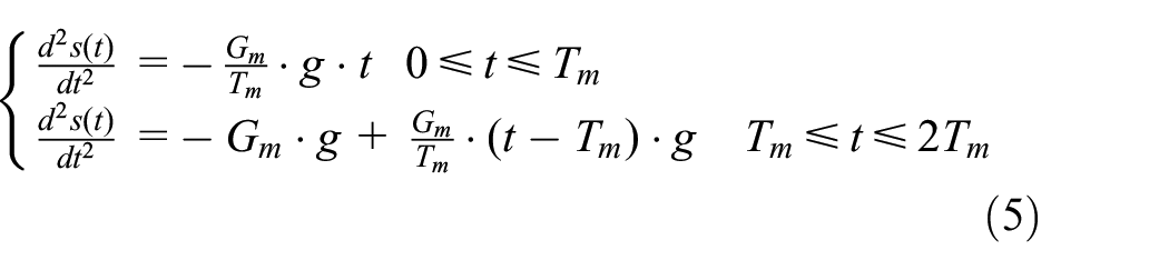
The velocity of helicopter is obtained by integrating equation (5), which is known from the boundary condition

Where, Gm, Tm refers to the maximum overload and the time of overload from zero to the maximum overload, respectively. According to the overload shown in Figure 2(a), the overload of occupant and movable components of crashworthy seat is given below.

Based on the coordination conditions of T1 = G1/Gm·Tm and the continuity condition of the velocity at t = T1, the velocity of occupant and movable components of crashworthy is obtained through integrating equation (7). At the time t = T1, the velocity of occupant is equal to the velocity of airframe. Based on the initial condition S(0) = 0 and the displacement continuous condition at time t = T1, the displacement of occupant and movable components of crashworthy seat could be obtained through integrating its velocity equations. Thereby, the displacement of movable components of crashworthy seat during the whole crash is obtained.

Therefore, the relative displacement between the occupant and the airframe of helicopter is determined.

Where, A = G1/Gm, Tm is the time when the helicopter reaches the maximum overload, Gm is the maximum overload, and G1 is the overload occupant borne during the operation of energy absorber. It should be noted that the stroke of energy absorption derived from equation (9) is the minimum value that the energy absorber must meet. However, due to the influence of stiffness of human body and crashworthy seat, various damping and issues during a crash, a certain margin should be considered for the stroke of energy absorption in the design.
Design of structural parameters
According to the principles of energy absorption above, an ideal energy absorber should have a stable load platform to make it move with a constant load during working process. In the study, the working load of ETEA refers to the stable load platform when the energy absorber is activated. The ETEA can quickly reach a stable load platform when working, which mainly depends on the plastic deformation and contact frictional force at the interfaces in the process of absorbing impact energy. The absorbing components consist of a cone head and a thin-walled expansion tube with smooth inner wall, and the diameter of the cone head is larger than that of the expansion tube. Under the impact of external loads, the cone head moves along the axis of the expansion tube, and forces the expansion tube to expand and deform, so as to absorb most of the impact energy. In addition, the friction between the cone head and the expansion tube also plays a important role in absorbing energy. The expansion deformation model of expansion tube is shown in Figure 5.

Expansion deformation model of expansion tube.
Here, the model above is simplified as an axisymmetric ideal plastic forming problem, and then the plastic mechanics is adopted to obtain the working load of ETEA. Under the premise of ignoring the stress through the thickness direction and the elastic deformation, the axial press exerted on the cone head can be formulated as follows.

Where, t, α, σs, ld, r1, r2, and μ refers to wall thickness of expansion tube, 1/2 cone angle of cone head, yield strength of material, length of calibrating straight, pitch diameters of expansion tube before and after expansion, and friction coefficient between the cone head and the inner wall of expansion tube, respectively. 20 r1 and r2 are important design parameters of the expansion tube, and here r2 = r1 + lk*tanα.
Before the design of structural parameters of ETEA, the following issues should be clarified and solved. First, the determination of the working load. In order to protect the safety of occupant, the design value of working load and the axial press exerted on the cone head are commonly assumed to be equal, that is, F = P. Second, since the design value of working load is also related to the physical properties, such as the yield strength of material and the friction coefficient between cone head and expansion tube, the mechanical and friction properties of expansion tube should be carried out in advance. After solving the issues above, the structural parameters of ETEA could be obtained through adopting MATLAB to grogram. Till now, the whole process of performance and structural parameters of ETEA are completed.
Through the above design procedure, the performance and structural parameters of ETEA were established. In the process of developing a new type of crashworthy seat, the main structural parameters of the expansion tube and cone head can be determined simply and quickly by clarifying the performance parameters, thereby reducing the difficulty of development and speeding up the project progress.
Validation of the proposed method
Calculation of structural parameters of ETEA
In this case, a crashworthy seat with two ETEAs was chosen as the research object, where the ETEAs were mounted vertically behind the basin of the seat as shown in Figure 4. The expansion tube of the ETEA belongs to the fixed part and was installed on the main pole. The cone head belongs to the movable part of the seat and was connected to the basin through the link rod. When encounter a crash, the occupant with the movable part of the seat moves downward relative to the helicopter, driving the cone head to move downward, forcing the expansion tube to expand, and absorbing the crash energy. In the process of seat development, the design method proposed is used to determine the performance and structural parameters of ETEA.
By substituting m1 + m2 = 87 (equals to the sum of the weight of an occupant and the movable components of a crashworthy seat) into equation (4), the working load required by a single ETEA was calculated, that is, F = 6708 N. From equation (1), the maximum acceleration borne by the human body can be achieved, that is, a = 144.3 m/s2. The stroke of energy absorption was obtained through substituting the value of a into equation (9), that is, S0 = 76.7 mm. Since the stiffness and damping effects were ignored in the method, the stroke of energy absorption was set to be 100 mm for the sake of safety. The pitch diameter of expansion tube after expansion is obtained through programing and substituting F, t, α, σs, ld, r1, and μ with 6708 N, 2 mm, 15°, 160 MPa, 3 mm, 13 mm, and 0.12 into equation (10), respectively. Here, r2 = 15.01, and lk = 7.50. Till now, the structural parameters of expansion tube and cone head are all obtained.
Validation through numerical simulation and tensile test
In order to observe the deformation behavior of expansion tube in the process of energy absorption, it is necessary to establish an experimental platform. However, it will cause many problems such as a long experimental period and great costs. Based on the considerations, the numerical simulation method was adopted to validate the consolidation of the proposed method, as it has been verified to offer advantages of high efficiency, low cost and practicability. The module of ABAQUS/Explicit was utilized to simulate the impact process of an ETEA.
To accelerate the solution procedure of the finite element model (FEM), the axisymmetric modeling technique was adopted to establish the FEM. In all simulations, one end of the expansion tube was fixed, and the other end borne the impact load exerted by the cone head. Here, as the total impact mass was 87 kg, the point mass exerted on the reference point of the cone head was set to be 43.5 kg as there were two ETEAs used in one crashworthy seat. The step time was 0.07 s, and the maximum acceleration exerted on the reference point of the cone head was 144.3 m/s2. As a comparison, the numerical simulation of the static loading process was also carried out with ABAQUS/Standard, while in that the time was set as default. In all simulations, the structural, frictional, and material parameters were the same.
Figure 6 shows the equivalent stress contour plots of the expansion tube during the impact process. It is found that the values of equivalent stress at the contact area between the expansion tube and the cone head are much larger than those in the other areas. In addition, the magnitudes of equivalent stress decrease after expending, that is, the deformed area shows an unloading phenomenon with the advance of the cone head.

Equivalent stress contour plots during expansion process: (a) t = 0.0026 s, (b) t = 0.0046 s, and (c) t = 0.007 s.
Figure 7 illustrates the load-displacement curves of expansion tube in impact and static processes. According to the figure, the load in impact process fluctuates greatly and its average value is 6278 N, having a relative error of 6.4% with the design value (6708 N). However, the vibration of load-displacement in static process is much smaller and located below the line of design value. Furthermore, the average value of working load in static process is about 6585 N, having a relative error of 1.8% with the design value. The numerical simulations demonstrate that the values of working load both in impact and static processes are slightly lower than the design value, proving that the proposed design method is valid and feasible.

Load-displacement curves of cone head.
To further confirm the validity and feasibility of the proposed design method, the static tension test of ETEA was carried out. The equipment adopted was an electrohydraulic servo universal material testing machine (UH-F500KNX), whose maximum force is 500 kN along with an accuracy level of 0.5 N. Figure 8 shows the tester and the load-displacement curve of the designed absorber. During the experimental process, the tester clamped the fixture fixed with one end of the energy absorber and pulled it, forcing the cone head to move along the axis of the energy absorber. The loading speed was 30 mm/min, and the loading displacement was 100 mm. It can be seen from Figure 8 that the load of the energy absorber quickly reaches the working load platform, then changes slowly within a certain range of values, and finally tends to be constant. The whole process is stable and the average value of the working load is about 6748 N. The relative errors of the working load to the design value and the value in static simulation process are 0.6% and 2.4%, respectively, conforming that the design method is solid and precise.

Load-displacement curve of expansion tube in static experiment.
Conclusions
In this study, the relationship between the lumbar load and the working load of ETEA was firstly established from the perspective of biomechanics, and a design method for the working load of ETEA was provided. Then, the computational model between the working load and the structural parameters of ETEA was further developed using the principal stress method. Thirdly, a type of ETEA was designed according to the design method and the computational model. Finally, the design method proposed in the study was validated to be accurate and reliable through the numerical simulation and experiments. According to the findings, the design method developed in this study can be used to design energy-absorbing systems for crashworthy seats of civilian helicopters.
Footnotes
Handling Editor: Chenhui Liang
Declaration of conflicting interests
The author(s) declared no potential conflicts of interest with respect to the research, authorship, and/or publication of this article.
Funding
The author(s) disclosed receipt of the following financial support for the research, authorship, and/or publication of this article: The work was supported by the Xiangyang Science and Technology Project (2021ABH004310, 2021ABH004215).