
Abstract
During the expansion forming of aluminum tube, the efficiency of heat exchanger diminishes due to the adhesion of groove and expansion ball inside the tube. Despite its importance, a limited number of researches on the adhesion problems in aluminum tube expansion have been published. This study aims to analyze the adhesion occurring during the expansion forming of aluminum tube for heat exchanger and to identify its location. For this, the method of using the statistical analysis of geometry by image processing and the slope of force measured from expansion forming was suggested. The new method discovers the adhesion location from the standard deviation of groove height measured before and after expansion of tube and the differentiation of force measured from expansion forming. To prove this method, the area with deviation of groove height above average was discovered, and it was confirmed that from the actual expansion of tube cross-sectional images, the height of some grooves was abnormally shorter due to adhesion. Also, from this method, it was confirmed that the changes in differentiation of force occurring from the expansion of the tube also include the information on adhesion location.
Introduction
The fin-tube heat exchanger is a heat transfer device used as condenser or evaporator in the refrigeration and air-conditioning sector and exchanges heat between the fluid flowing inside the tube and external environment through the fin connected with the tube. As the efficiency of heat exchanger is directly affected by the forms of the fin and the tube, the effect of various forms of fins and tubes has previously been studied by calculating thermal contact conductance between fins and tubes. 1 Furthermore, Tang et al. 2 have proposed a new methodology for improving the thermal contact conductance performance at the expansion forming process. Recently, the effect of tube geometry on heat exchanger efficiency has been studied, 3 and heat exchanger coefficients and pressure drop for various tube geometries have been computed. 4 Products with inner grooved tubes have shown increases in the heat exchange efficiency by 100% 5 and 111%–207% 6 higher than those with smooth tubes. Regarding tube materials, although most use copper as the material of tube, aluminum is considered to be used for some applications such as air conditioners because of its cheaper material and production cost as well as its lighter weight, compared to copper. Aluminum tubes are one-fourth times cheaper and 35% lighter than copper tubes. 7 Furthermore, aluminum tubes have shown higher heat transfer efficiency by 136% with inner grooved geometry than without it. 7 It has also been investigated that Al-Cu composed tubes have reduced the material cost of the heat exchangers, but guaranteed heat exchanging performance. 8
In the manufacturing process of fin-tube heat exchanger, the expansion forming that expands the outer diameter of tube in order to make sure that the tube and fin are securely joined together is required to increase heat exchanging efficiency. However, in this expansion forming, adhesion occurs between the fin and tube because the upper portion of inner grooves sticks to the surface of expansion ball. This adhesion occurs more in aluminum tubes than copper tubes and can be observed by measuring the height of inner groove. 8 Adhesion phenomenon can diminish the performance of heat exchanger as adhesion causes irregularity of tube expansion and loss of inner grooves.
Most researches done on expansion forming process and heat exchanging efficiency have been focused on the driving force during expansion and/or the level of expansion dependent on the groove geometry as well as expansion ball geometry, 9 through simple expansion experiments and finite element analysis. For the level of expansion, Lee and Park 10 have compared non-uniform grooved tube with uniform grooved tube. Almeida et al. 11 have studied the driving force during expansion dependent on expansion ball geometry, while Seibi 12 has found the effect of expansion ratio and expansion ball angle on the expansion force through simple expansion experiments. Numerical analyses have also been conducted to improve the expansion process 13 and to measure changes in the driving force between diverse expansion balls of various sizes and a smooth tube. 14 Some investigators have evaluated heat exchanger performance by measuring the expansion ratio that represents the fin-tube contact quality, 15 while others have optimized tube expanding process to maximize heat exchanging efficiency. 16 Moreover, the heat exchanging efficiency has been improved by optimizing the expanding velocity for tube expanding process, 17 and structural integrity of expansion balls and tubes has been numerically validated by calculating the stress fields produced on tubes during expansion process. 18 However, the tube material in these studies has been limited to copper, without using aluminum tubes.
Therefore, this study aims to investigate the adhesion phenomenon in aluminum tubes with inner grooves during its expansion forming process as well as the location of adhesion in aluminum tubes and to propose a new method of predicting the occurrence and the location of adhesion during expansion forming. For this, experiments simulating the expansion forming process were performed on aluminum tubes, and the images of tube cross sections before and after expansion were analyzed. Through the image processing method on the cross-sectional images captured, the adhesion phenomenon in aluminum tube expansion was investigated, and based on these results, a new method of predicting the occurrence and the location of adhesion was suggested from the driving force of aluminum tube expansion.
Adhesion in aluminum tube expansion forming
The manufacturing process of heat exchangers includes the expansion forming that joins the fin and tube. Expansion forming is a metal forming process that increases the outer diameter of tube by passing the expansion ball with diameter greater than its inner diameter through the tube (Figure 1). Expansion balls with increased hardness, obtained by coating or heat processing, are often used for repeated expansion work. The surface of expansion balls with increased hardness is stained with aluminum after expansion forming; this is due to the adhesion phenomenon. Adhesion phenomenon is a form of abrasion and refers to the phenomenon in which, during the friction of two surfaces, the surface with lower hardness breaks due to the friction heat and sticks to the surface with higher hardness. 19 In fact, this adhesion phenomenon frequently occurs during expansion forming at factories. The adhesion of expansion ball results in the loss of product manufacturing time and cost due to replacement of expansion balls and diminished quality of heat exchangers.
Schematic of forming process in aluminum tube expansion.
Expanding experiments
During the processing procedure, it is required to identify the frequency of occurrence and occurrence time of adhesion phenomenon to prevent performance degradation of heat exchangers. To determine the adhesion phenomenon occurring from expansion forming, expansion simulation experiment was performed (Figure 2). Expansion simulation experiment can be largely divided into expansion experiment and data collection. We create expansion using the alternating current (AC) single-axis controller (RCS-6000G; Robostar, Korea) to push the expansion ball into the grooved aluminum tube. Here, the driving force between expansion ball and tube is measured using the load cell (CDFS-100; Bongshin, Korea; Figure 3).
Apparatus for the tube expansion experiment. Expansion ball is attached to the end of expansion device, and the force delivered through expansion ball is measured by load cell.
Experimental measures of the driving force in aluminum tube expansion.
Image processing for the cross section of tube
Looking at the force graph generated during expansion, over a certain level of force is required for expansion. However, it is hard to determine only from the force graph where the adhesion started. Therefore, there is a need to precisely analyze the internal information of plastic deformation by taking the cross-sectional images of the expanded tube, and for this, image analysis method was used.
The cross section of aluminum tube was taken after completion of expansion forming, and to obtain the boundary data, 330 mm of the expanded part was cut into 10 mm intervals and the cross section was taken. When taking the image of each cross section, the cross section was polished using 1 μm diamond suspension, and then, the image was taken using an optical microscope (Nikon LV100D; Japan). From the obtained cross-sectional images, the boundary data of aluminum tube were obtained using image binarization. The boundary data were divided into the outer boundary on the outside and the inner boundary on the groove side.
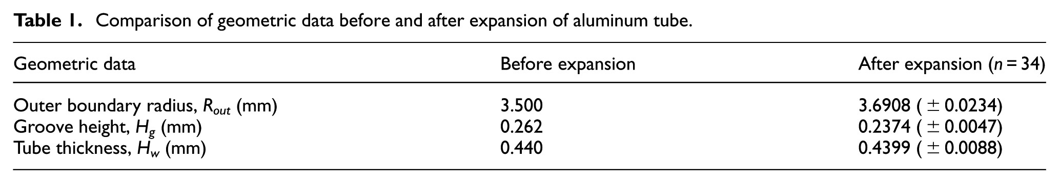
To calculate the radius inside the aluminum tube, each cross-sectional image was rotated and the distance from the center was calculated. The center of the tube was located in the image, the image was then rotated counterclockwise with intervals of 0.1° based on the center, and then the continuous inner and outer boundaries of the tube was reconstructed by the linear interpolation of the discrete inner and outer boundary image data (Figure 4). The distance from the center of the tube to the continuous inner and outer boundaries was calculated according to the relation of 1 pixel = 0.0048 mm and then was aligned by the angle generated when the cross-sectional image of the tube was rotated counterclockwise. Then, the spread-out state of the cross section of the tube was plotted by the distance between the center and the inner and outer boundaries of the tube versus the rotation angle (Figure 5). Using the obtained boundary data, the variables for the radius inside the aluminum tube and groove were defined (Table 1, Figure 6). Rga and Rgb refer to the radius to the apex of the groove and to the bottom in the inner boundary, respectively, and Rout refers to the radius to the outer boundary. Hg is the groove height and Hw is the tube thickness or the distance from the center of two points on the bottom of groove to the outer boundary, which can be calculated in the following formula


The image analysis method for measuring the distance from the center to groove and the distance to outer boundary. While rotating the boundary data obtained from cross section by 0.1°, the distance between the groove meeting with the horizontal diagonal line from the center toward 0° and the outer boundary is measured. If there is no point where horizontal line meets the boundary, the point of intersection by linear interpolation on two points adjacent to the boundary is acquired.
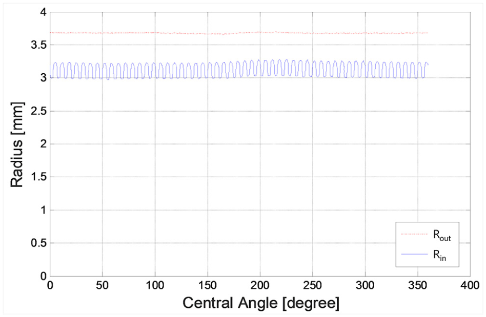
Graph of the cross section at a tube length of 90 mm recalculated from the center of the cross section to the groove and the outer boundary.
Comparison of geometric data before and after expansion of aluminum tube.
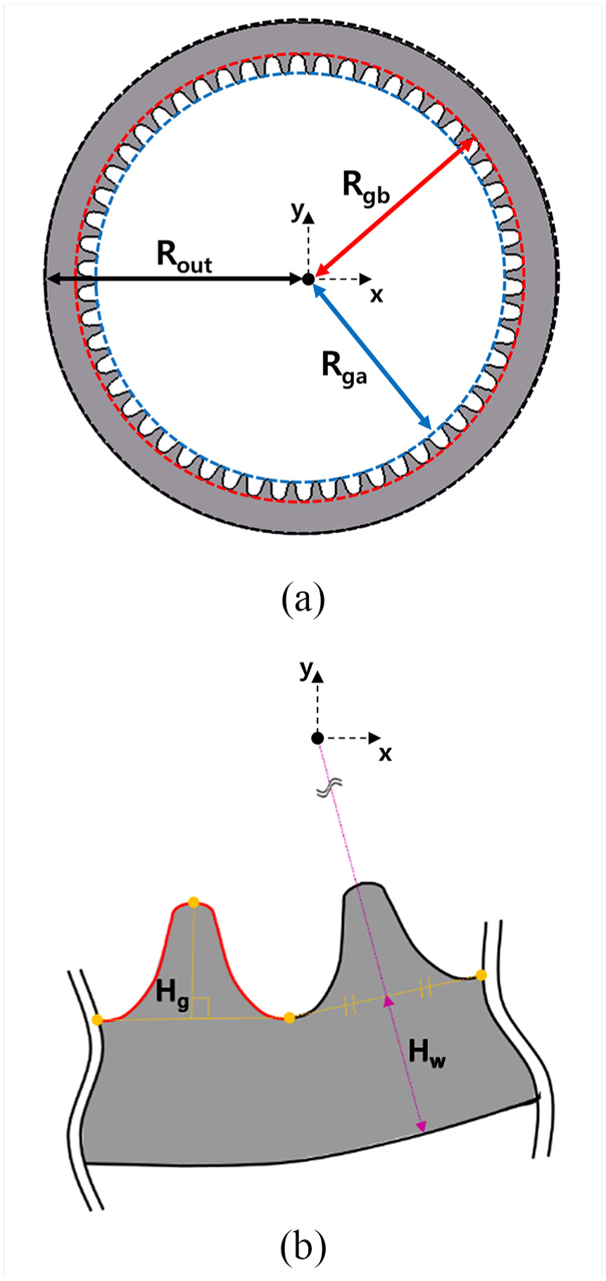
Summary of geometric variables of cross section. (a) Outer boundary radius (Rout) is the distance from center to the outer boundary, groove apex radius (Rga) is the distance to the apex of groove, and groove bottom radius (Rgb) is the distance to the bottom of groove. (b) Groove height (Hg) is the length of the vertical segment to the segment made by connecting two dots on the left and right from the apex of groove to the bottom of groove. Tube thickness (Hw) is the distance from the center of segment connecting two dots on the bottom of groove to the outer boundary, and the extension of segment for measuring the thickness as shown passes the center.
To examine the relationship between the change in each variable to cross section and the adhesion phenomenon, the data obtained from each cross section were statistically processed (Figure 7). As the total number of grooves for one cross section is 54, averages and standard deviations (SDs) of the groove height (Hg), tube thickness (Hw), and outer boundary radius (Rout) values for each cross-sectional image were calculated. In particular, when we use SD values, these values are small. Therefore, we used normalized values of SD (i.e. ratio of SD) that was calculated by the ratio of SD to the average size of the groove height before expansion and expressed as percentage for comparison. This ratio of SD (i.e.


The graph of statistically processing the data obtained from image processing each cross section. After calculating (a) outer boundary radius (Rout), (b) groove height (Hg), and (c) tube thickness (Hw), the average and the standard deviation of each data were indicated to the cross-sectional location of tube.
Results and discussion
The geometric data were obtained from image processing, and then, the cross section of tube before and after expansion was compared (Figure 8). Compared to before expansion, outer boundary radius (Rout) increased by 0.1908 mm (5.45%) and groove height (Hg) decreased by 0.0246 mm (9.49%). The tube thickness (Hw) did not show great difference compared to before expansion (Table 1).

Comparison of cross section: (a) before and (b) after expansion. It shows that groove height and tube thickness changed due to plastic deformation as it went through expansion forming.
The Hg was uneven in the area with high SD of groove height (Hg) and was low in some grooves (Figure 9(a)). The fact that the height of some grooves was greatly lower than others reflects the loss of material forming the grooves. The adhesion phenomenon occurred during expansion forming is the estimated cause of groove loss, and from the cross section of an area with large SD of Hg, grooves of abnormally low height were observed (Figure 9(b)). Also, in the cross-sectional image of the same area after actual expansion, abnormally low height compared to other grooves was confirmed (Figure 10). Therefore, it is estimated that the areas at 30, 160, 190, 230, and 250 mm with higher than average SD are the areas of adhesion.

(a) The higher values of standard deviation ratio of groove height (the ratio of standard deviation of groove height to its size before expansion) than its average noted by circles predict adhesion location and (b) the smallest groove height (Hg) value in the tube cross section at a tube length of 230 mm supports the adhesion of that groove.

The cross-sectional image showing the difference in groove height after expansion. The point of abnormally low groove height was confirmed from the cross-sectional image at 230 mm which is the adhesion location estimated by analyzing the standard deviation of groove height.
The expansion process of aluminum tube is a process which involves expanding the ball to expand the outer wall with grooves by inducing the tube inside to undergo plastic deformation. This process is a form of plastic deformation where the force expanding the diameter of tube and the friction force between materials act as the reaction force to the expansion ball. In this process, adhesion occurs when the aluminum sticks to the expansion ball before some grooves experience sufficient plastic deformation due to increase in local friction heat. Assuming that the force required for expansion of tube is constant, the change in force during expansion includes the change in friction due to adhesion. Therefore, in this study, in order to verify the occurrence of adhesion, we examined the increase and decrease in force by differentiating the force data obtained from expansion experiment over time.
In order to examine the change in force from adhesion, more detailed understanding in adhesion phenomenon is required. Heat is continuously generated from the friction of expansion ball and groove from the expansion forming, and locally, adhesion occurs where the groove and expansion ball stick to each other. Although friction mainly occurs between the aluminum and the steel expansion ball before adhesion, local friction partly occurs between aluminum and other aluminum attached in the expansion after adhesion. Generally, the friction factor between aluminum and steel is approximately 0.45–0.61, but in contrast, the friction factor between aluminum and steel is high at 1.05–1.35. 20 Therefore, in case of adhesion, momentary change in force occurs. As this is a local phenomenon, it is hard to observe from the overall data, but the adhesion phenomenon can be observed when the force is differentiated over time and viewed by the formation of its increase and decrease (Figure 11).

The graph of differentiation value of force and standard deviation of groove height. The peak point when force is differentiated over time, in other words, the point where the inclination of force rapidly increases, shows similar trend with the segment with large Hg standard deviation.
There are largely two reasons that the confirmed adhesion location does not precisely match. First, it is because the actual aluminum tube contracts in the axial direction in the expansion experiment. The aluminum tube of 400 mm before expansion contracts by 20 mm of length after expansion. The force generated during expansion was expressed relative to the location of tube before expansion, while geometric data summarize the location of tube after expansion, leading to difference in location. Second, as the geometry was obtained from the cross section of cutting the tube with an interval of 10 mm, there is less continuity of SD of groove height compared to the continuous force data. Therefore, there is a slight difference for the SD of groove height to follow the change in the derivative of the continuous force data over the tube length. When taking into consideration these aspects, it can be regarded that the locations of adhesion estimated by two methods nearly match. However, although the change in differentiation data is related to the adhesion of the groove height as explained above, the fact that the actual aluminum tube contracts in the axial direction in the expansion experiment results in the overall increase in the driving force as a function of expansion ball location (Figure 3). Moreover, in the driving force, initially there is a sudden increase in the expansion ball location of 0 to ∼5 mm (Figure 3) that presumably occurs while the expansion ball with a length of 5 mm is being inserted.
There are several researches related to expansion forming using the driving force of expansion because it is the easiest to measure the force from related experimental data. However, as mentioned earlier, the existence of adhesion during expansion cannot be determined only from the force data, and even if the change in force is examined, it cannot be the sole basis to predict the occurrence of adhesion. Therefore, this study determined the occurrence of adhesion using the statistical data of groove height obtained from image processing of cross section after expansion and the cross-sectional images. Using these results, it was confirmed that the change in the slope of force (i.e. the differentiation of force) during expansion is closely related to adhesion.
Conclusion
This study suggests a new method to correlate differentiation of expansion force measured through expansion forming processes with a statistical analysis of the geometry derived from image processing in locating the adhesion sites occurring at the expansion forming process of aluminum tubes for heat exchangers. Here, geometric data obtained by image processing of tube cross sections are outer boundary radius, groove height, and tube thickness before and after the expansion, while force at the expansion forming process was measured through experiments. The location of adhesion was estimated using not only the SD of the groove height—a geometric data that have much to do with the adhesion—but also the differentiation of force occurring at the expansion. In this study, the adhesion was evidenced through investigating actual cross-sectional images, and it was confirmed that the adhesion location is related to a sudden increase or decrease in the expansion force. It was also confirmed that using the variation in the slope estimated using the derivative of the expansion force versus time, it can be determined whether or not adhesion occurred.
Footnotes
Acknowledgements
H.K. and K-H.K. have contributed equally to this work.
Handling Editor: Min Zhang
Declaration of conflicting interests
The author(s) declared no potential conflicts of interest with respect to the research, authorship, and/or publication of this article.
Funding
The author(s) disclosed receipt of the following financial support for the research, authorship, and/or publication of this article: This research was supported by the National Research Foundation of Korea (NRF) grant funded by the Korean Government (MSIP; No. NRF-2016R1A2B4012561); by Engineering Development Research Center (EDRC) funded by the Ministry of Trade, Industry & Energy (MOTIE; No. N0000990); and by “Human Resources Program in Energy Technology” of the Korea Institute of Energy Technology Evaluation and Planning (KETEP) grant funded by the Ministry of Trade, Industry & Energy, Republic of Korea (No. 20164030201230).