
Abstract
Vehicle longitudinal dynamics system has the characteristics of being strongly non-linear, time-varying, and multiple-perturbed, so, it is difficult to build the mathematical model accurately. The control algorithms, based on accurate mathematical model, can hardly achieve the ideal effect, but control methods, which merely adopt input/output data (I/O) of a system, provides a solution. In this paper, by means of combing model-free adaptive control (MFAC) and sliding-mode control (SMC), the model-free adaptive sliding mode control (MFASMC) method is proposed. By comparison with feedback-feedforward control method, the MFASMC method can better improve the control effect and anti-disturbance performance. Meanwhile, the stability of MFASMC method was proven mathematically. Besides, the parameters of MFASMC method were optimized using genetic algorithm. Results of simulation and HiL test shows that the MFASMC method has fast response, strong robustness and smooth output. It would be better to apply it to the longitudinal dynamics control of intelligent vehicles.
Keywords
Introduction
According to the intelligent degrees of vehicles, SAE divided intelligent vehicles into six levels. Before realizing high-level automatic driving, advanced driver assistance system (ADAS) has become an important research topic. 1 As the basis of longitudinal control functions (adaptive cruise, automatic braking system, active collision avoidance system, etc.), vehicle longitudinal dynamics control method plays a very important role in the control of intelligent vehicles. As shown in Figure 1, the vehicle longitudinal dynamics control system includes the driving system, braking system and the switching logic between them. The desired acceleration is tracked by the driving/braking control system, then the control system outputs desired throttle opening/braking pressure, the throttle opening/braking pressure will be the input for the vehicle longitudinal dynamics system. It is well known that the system has the characteristics of non-linearity, time-variation and disturbance-variety. 2 Meanwhile, the vehicle itself has the issue of parameters uncertainty during driving, the system is also affected by external disturbances such as road friction coefficient, road slope and air resistance. Therefore, it is difficult to establish an accurate model to describe vehicle longitudinal dynamics. If a simplified model is established, it would be difficult to achieve good results in the design of the controller. 3

Vehicle longitudinal dynamics control system.
As for the research on vehicle longitudinal dynamics system, many scholars idealized the vehicle longitudinal dynamics model. For example, Hou et al. 4 simplified the vehicle driving/braking system by the first-order transfer function and the properties of torque measured on the engine bench, then the accuracy of the simplified model was verified by comparing the simulation result with the experimental result. Jiaxu Zhang 5 presents a novel nonlinear robust wheel slip rate tracking control strategy for autonomous vehicle with actuator dynamics. Hsiu-Ming Wu 6 proposes a multiple sliding-mode control (MSMC) strategy based on the stator flux oriented vector scheme for speed control of three-phase AC induction motor (IM) drives in the presence of an external disturbance and uncertainties. Xu and Ioannou 7 obtained the first-order model by linearizing the nonlinear vehicle model with Taylor expansion, but the vehicle model is a time-varying system, which contradicts its assumption that the model is time-invariant. These methods of model simplification relied on accurate experimental data, the generalization of model was poor, and the nonlinear factors of the closed-loop system were not fully considered, so it’s hard to achieve ideal control effect.
In order to track the desired acceleration accurately, the driving/braking control system needs to be designed. The common method is to establish the inverse longitudinal dynamic model. The desired acceleration can be converted to the desired throttle opening/braking pressure through the inverse model of driving/braking dynamics. For example, based on the inverse longitudinal dynamics model and PID control algorithm, Moon and Yi of Seoul National University 8 designed the feedforward-feedback control method of longitudinal dynamics. Based on the sliding mode control method and the inverse longitudinal dynamics model, Berkeley realized the tracking of the desired torque by driving/braking actuator. 9 However, the design of reverse longitudinal dynamic model involves too many parameters of vehicle, so the model is complex.
Based on the above research, in order to avoid the design complexity of vehicle longitudinal dynamics and driving/braking control system, as well as meet the needs of nonlinear time-varying systems, the model-free control method provides a solution. Model-free adaptive control (MFAC) is a data-driven control method proposed by Hou and Jin of Beijing Jiaotong University, which only relies on the input/output (I/O) data of the controlled object to establish the model instead of the accurate mathematical model. In addition, the method also has characteristics of strong adaptability and robustness. 10 The method was widely used in many fields, such as robot bionic device, 11 aircraft control, 12 wind turbine control, 13 vehicle lateral, and longitudinal control,14,15 etc. But its disadvantage is that the control effect is bad for the hysteretic system. Sliding-mode control (SMC) is an effective control algorithm to deal with nonlinear control problems. 16 The design of the control method is independent of system state and parameters. Meanwhile, SMC method has good robustness under external disturbance and model uncertainty. However, design of SMC needs the accurate mathematical model of the controlled system, and its problem of chattering is well known.17,18
In this paper, considering the characteristics of strong non-linearity, time-variation and multi-disturbance, by means of combining MFAC with SMC, the longitudinal control method based on driving/braking control system was designed to realize model-free and strong anti-disturbance control.
MFASMC control scheme for vehicle longitudinal dynamics
Vehicle longitudinal dynamics controller generally includes driving controller and braking controller, which are subdivided into throttle opening controller, braking pressure controller and switching logic between them.
19
In this paper, a data-driven control method is proposed based on MFASMC. The control logic is shown in Figure 2,

Longitudinal control system based on MFASMC method.
Nominal parameters of vehicle model.

In order to realize the smooth switching between braking and driving control algorithms, hysteresis switching logic needs to be designed.20,21 As well known, if the desired acceleration is more than 0, the driving control mode needs to be adopted to increase the throttle opening. Besides, releasing the accelerator pedal or pressing the braking pedal can achieve negative acceleration. Therefore, when the desired acceleration is less than 0, it can be achieved through the driving system or braking system. In order to design the switching logic, set the throttle opening to 0 at different speeds to get the maximum deceleration value of vehicle on this condition, then draw the maximum deceleration curve. In order to ensure comfort and reduce frequent switching, the switching logic curve is shifted up and down by 0.01 m/s 2 to form a transition zone. As shown in Figure 3, the driving control area is above the transition area, and the braking control area is below the transition area. The control mode is not switched in the transition area.
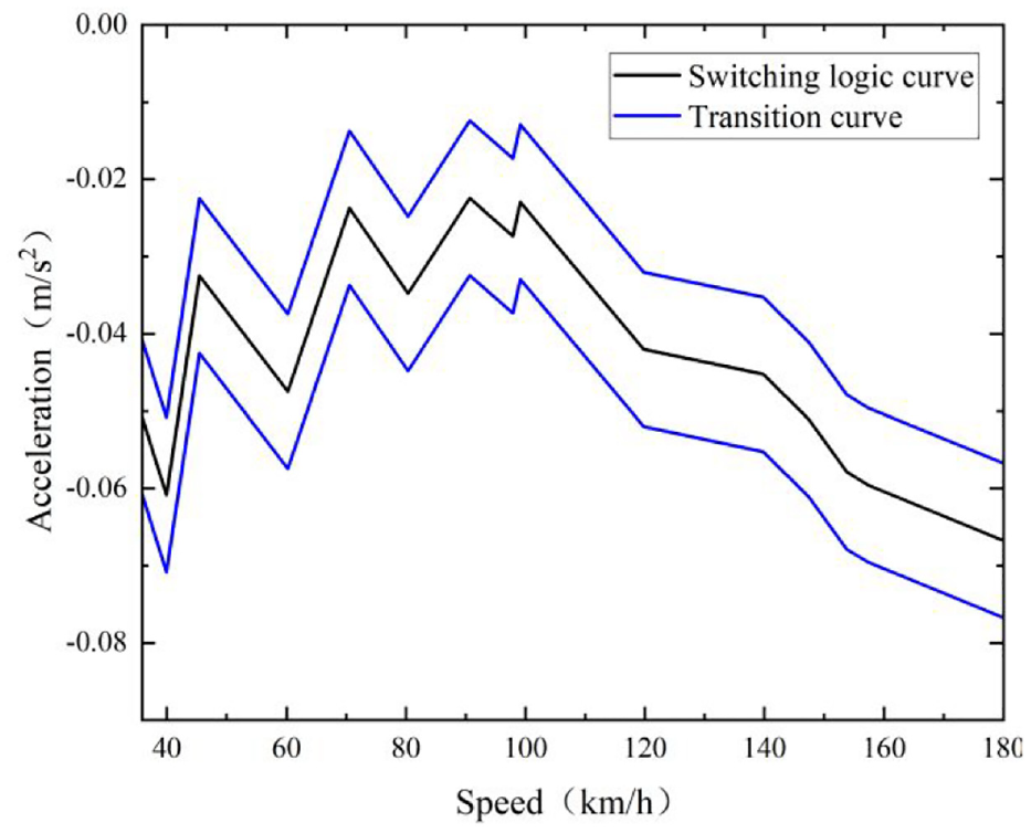
Driving/braking switching logic curve.
MFASMC model of drive/brake dynamics control system
MFAC model
Based on a model-free adaptive control technology, 22 the longitudinal driving and braking dynamic system can be expressed as in equation (1):

Considering the characteristics of time-varying and multiple external disturbances of the vehicle dynamics system, this paper introduces external disturbances
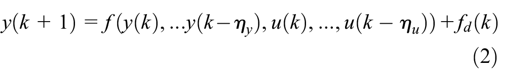
Where
It is assumed that the system meets the following two conditions:
Except for a finite time point, the partial derivative of
The above system meets the condition of

Where
When:

If


Where
If the sampling time is short, in equation (5)

Equation (6) can be rewritten as equation (7).

Since
The function of control input criterion can be shown in equation (8)

Where
By substituting equation (5) into equation (8), finding the derivative with respect to
Where,
Considering PPD-

Where
In equation (10), the gradient estimation method can be obtained by finding the extreme of

Where
According to equation (9) and equation (11) the MFAC algorithm is presented in equation (12):
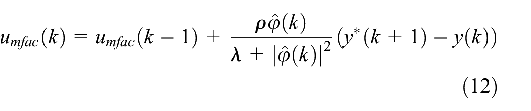
Where,

Where,
Control algorithm of MFAC-SMC
MFAC controller does not need the model of controlled system, and sliding mode controller (SMC) has the characteristics of fast response and strong anti-disturbance. This paper combines MFAC with SMC to obtain the advantages of both.
The tracking error is defined as equation (14):

Where,
The sliding-model control is shown as equation (15):

Equation (16) can be obtained as follows:

The discrete sliding reaching law is designed as equation (17):

Where
Substituting equation (16) into equation (15), equation (18) can be obtained.

Setting

As shown in the Figure 4, the steps of MFASMC method of driving/braking dynamics system are summarized as follows:
The estimated value
The estimated value

The steps of MFASMC method.
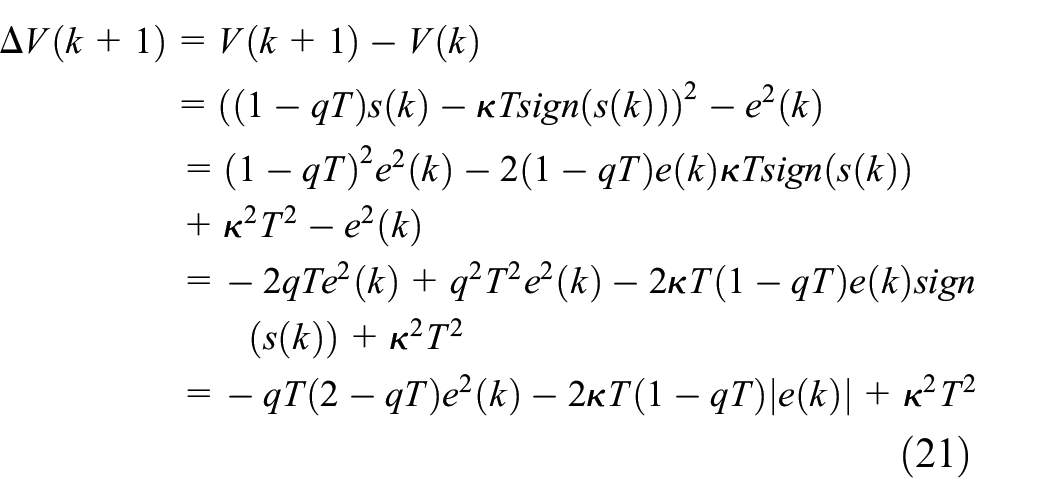
Analysis of stability
To demonstrate the stability of the designed control system, the hypothetical conditions are given as follows:
Except for a finite time point, the partial derivative of
The above system meets the condition of
For a given bounded output
For any
The condition (c) is a necessary point for the controllability of system, and the condition (d) indicates that the corresponding output should not decrease when the control input increases, which can be considered as quasi-linear features of the system. Obviously, the vehicle system meets the above assumptions.
When the vehicle system meets the conditions (a), (b), (c), and (d), combining equation (19) with equation (13), if the desired signal
The tracking error of the system can converge in a fixed-time.
The system is stable, which has bounded input
The proof of the definition are given in the following equations :
Define:

Parameter optimization of MFASMC based on genetic algorithm
Based on the above research, it can be seen that there are five unknown parameters

Wherein,
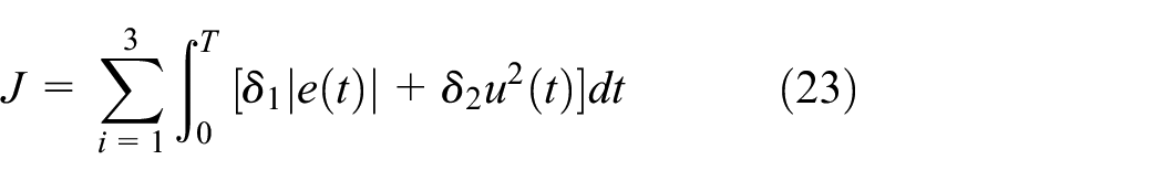
Where

The parameter values of genetic algorithm are shown in Table 2.
Parameter value of genetic algorithm.

The flowchart of calibrating the optimal parameters of MFASC with genetic algorithm are shown in Figure 5. Firstly, the parameters to be calibrated in the algorithm are binary coded, and then the initial values of 100 individuals in the population are determined. Secondly, the fitness of each individual is calculated based on the fitness function, and the best individual is selected to replace the worst individual. Finally, the individuals cross and mutate to judge whether they meet the requirements of optimization. If they meet the requirements, they return to the optimization step. If they meet the requirements, they output the final calibration results.
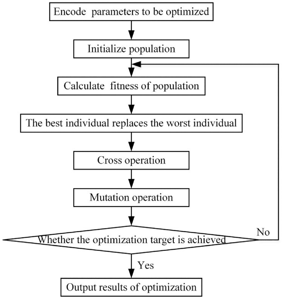
Flowchart of genetic algorithm.
The results of optimized parameters of MFASM controller are as follows:

Simulation analysis
Longitudinal dynamic control method based on classical feedforward-feedback
Classical feedforward-feedback control method is also a model-free longitudinal dynamics control method, which has made many applications in the longitudinal control of intelligent vehicles, 8 The nonlinear and time-varying characteristics of longitudinal dynamics were compensated by feedforward of inverse longitudinal dynamics model. The deviation between desired acceleration and actual acceleration was compensated by feedback of PID algorithm. 26 In order to verify the effectiveness of the MFASMC method proposed in chapter 2, it was compared with the feedforward-feedback method, which is commonly used in longitudinal control. The tracking performance of the two methods under the same desired input needed to be contrasted, as well as the robustness under external perturbation. The longitudinal dynamic control method based on feedforward-feedback is shown in Figure 6.

Longitudinal dynamic control algorithm based on classical feedforward-feedback.
In order to realize control algorithm based on classical feedforward-feedback, an inverse longitudinal dynamics model was established to convert the desired acceleration input into the desired throttle angle or desired cylinder pressure. The inverse longitudinal dynamics model includes the inverse driving dynamic model, the inverse braking dynamic model and the switching logic between them.
Assuming that the vehicle is traveling on an inclined road and the vehicle itself is a rigid body, the force analysis of the vehicle is shown in the Figure 1. The tire on the axle is subjected to longitudinal force and normal force. 27 Other external forces acting on the vehicle include air resistance, rolling resistance and gravity. 28 The force equilibrium equation of the vehicle in the forward direction is as shown in equation (25)29:

Where:

Where
The desired engine torque

Under driving conditions, by ignoring the effects of throttle lag time and torsional rigidity of the drive shaft on engine performance, the steady output torque of the engine

Where,
According to the engine data of a class-B vehicle, the torque characteristic function of the engine can be obtained by interpolation. The model can be used to represent the relationship between output torque


Throttle opening characteristics of engine.
For braking conditions, the pressure of main cylinder is considered to be linearly related to the braking force applied to the wheels. Therefore, under braking conditions, the desired braking pressure

The switching logic of driving/braking is the same as that in section I.
Comparison between MFASMC control method and classical feedforward-feedback control method
Comparing the effects of two control methods under different typical desired acceleration.20,30
Step input response
The step acceleration signal with amplitude of 0.8 m/s 2 was designed to verify the tracking ability and response capability of the two control algorithms. As shown in Figure 8, during the step input process of 30 s, it could be seen that both the MFASMC controller and the classical feedforward-feedback controller could achieve a good tracking performance under the expected acceleration, while the MFASMC had a faster response speed and was conducive to reducing the overshoot under the desired acceleration jump. It could also be found that the acceleration output was smoother and the change of throttle opening was more gentle, which indicates that the MFASMC controller can obtain better dynamic response under step input and improve ride comfort.

Step input-response: (a) acceleration tracking comparison, (b) throttle opening comparison, and (c) braking pressure comparison.
Ramp input response
The ramp acceleration signal with amplitude of 0.8 m/s 2 was designed to verify the response capability of the two control methods. As shown in Figure 9, it can be seen that the acceleration responses of the two control methods were quite similar. Classical feedforward-feedback control method jittered intensely when the desired acceleration decreased. In fact, when the vehicle slowed down abruptly after constant acceleration, the vehicle would shake. The MFASMC algorithm was beneficial to mitigate the dither and enhance the ride comfort.

Ramp input-response: (a) acceleration tracking comparison, (b) throttle opening comparison, and (c) braking pressure comparison.
Impulse input response
The pulse acceleration input with duration of 1 s and amplitude of 1 m/s 2 was set up to verify the pulse response capability of the two control methods. As shown in Figure 10, the classical feedforward-feedback control method had a large overshoot, and the oscillation became more obvious with increase in vehicle speed. The MFASMC control method had a shorter adjustment time, which also improved the problems of overshoot and oscillation.

Impulse input-response: (a) acceleration tracking comparison, (b) throttle opening comparison, and (c) braking pressure comparison.
Comprehensive working condition test
The comprehensive working conditions of city/town with a duration of 600 s were set up to contrast the anti-disturbance capability and fuel economy of the two control methods.
In order to compare the anti-disturbance capability of the two control algorithms, three time-varying disturbances; gradient, air resistance and friction coefficient were imposed on the vehicle longitudinal dynamics system. The variation curve of gradient with displacement is shown in Figure 11, and set a certain time-varying wind resistance in the simulation scene. Besides, in order to simulate ice and snow weather, the variable friction coefficient is set in the simulation, which is a sinusoidal signal with a maximum value of 0.8 and a minimum value of 0.4.

Path elevation.
From Figure 12(a), under external disturbances, the classical feedforward-feedback control method had poor robustness, large overshoot and obvious dither, which was bad to ride comfort. From Figure 12(b) and (c), the dither of throttle opening and brake pressure were also frequent, which led to the reduction of the service life of the driving/braking actuator. As shown in Figure 12(d), the MFASMC control method not only reduced the dither of acceleration, but also improved fuel economy.

Comprehensive working condition simulation: (a) acceleration tracking comparison, (b) throttle opening comparison, (c) braking pressure comparison, and (d) fuel consumption diagram.
Hardware-in-the-loop test
In order to verify the control effect of the longitudinal control method and the effectiveness in the real controller, this paper carried out the hardware in the loop simulation test for the above control strategy as shown in Figure 13. The overall test block diagram is shown in Figure 14.

HiL test equipment: (a) upper computer, (b) VCU controller, and (c) test cabinet.

Diagram of HiL test.
From the Figure 15(a), it can be seen that, compared to the simulation, the accuracy of real vehicle acceleration data by HIL test was lower, but it could also track the desired acceleration well. The acceleration trajectory of HIL test was almost consistent with the desired acceleration, and there were no problems of overshoot and oscillation. It can also be seen from the Figure 15(b) and (c) that, compared to HIL test and simulation, there was a certain jitter of throttle opening and braking pressure, but it was within a reasonable range, which met the requirements of ride comfort. Besides, the frequent switching of the driving/braking actuator was reduced, which was beneficial to prolong the service life. It shows that the control strategy designed in this paper has good control effect.
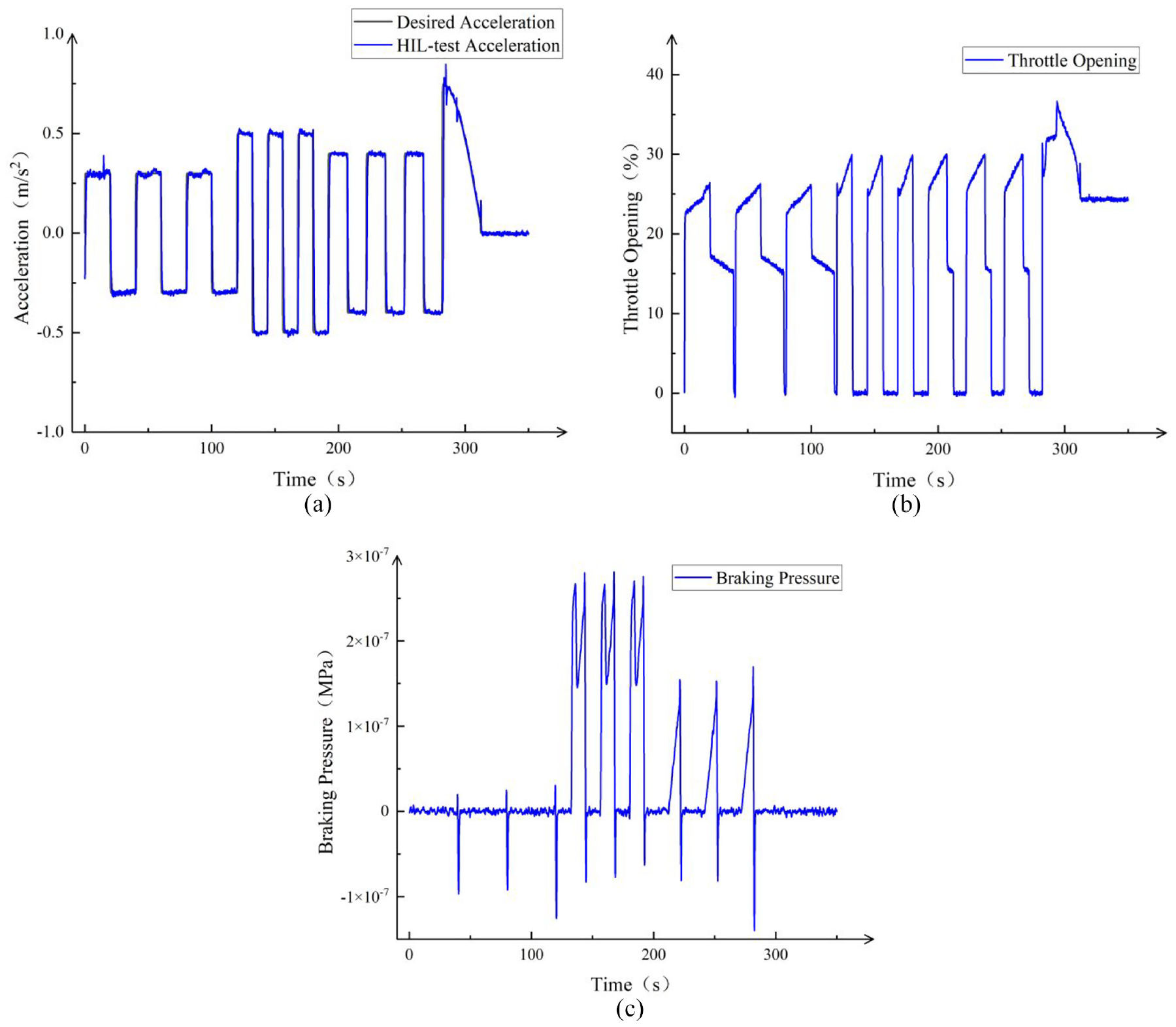
Results of HiL test: (a) acceleration tracking comparison, (b) throttle opening comparison, and (c) braking pressure comparison.
Conclusion
In this paper, longitudinal dynamics controller of intelligent vehicle was designed based on MFASMC control method, and the driving/braking switching strategy was designed based on CarSim data. Then the controller parameters were optimized by genetic algorithm. Compared to the model-based control method, this method only relied on I/O data without accurate model, which reduced the difficulty of longitudinal controller design.
In order to improve the effect of MFASMC algorithm under typical working conditions, the cost function is designed based on genetic algorithm. Five undetermined parameters of MFASMC algorithm are optimized under three typical working conditions: step input response, ramp input response and impulse input response.
In order to verify the effectiveness of MFASMC controller, the two methods were compared under typical input conditions and comprehensive condition. The simulation results show that the MFASMC controller designed in this paper can accurately track the desired acceleration input signal. It not only has short adjustment time, small overshoot and small oscillation, but also has strong robustness under external disturbance. In addition, it is also conducive to improve the fuel economy of the vehicle.
In order to verify the feasibility and effectiveness of MFASMC algorithm in the actual controller, the Hardware-in-the-loop platform is built. The results show that the acceleration trajectory measured by HIL is consistent with the desired acceleration, and there is no large overshoot and chattering. Therefore, the control strategy designed in this paper has good control effect.
Footnotes
Handling Editor: Chenhui Liang
Declaration of conflicting interests
The author(s) declared no potential conflicts of interest with respect to the research, authorship, and/or publication of this article.
Funding
The author(s) disclosed receipt of the following financial support for the research, authorship, and/or publication of this article: This work was supported by the National Natural Science Foundation of China under Grant 51675235.