
Abstract
Shrink-fit assemblies have been used to offer a more robust running surface for wooden wheels for a long time. Generally, the two parts are cylindrical or conical. Shrink-fit is now an operation that involves creating contact between two cylinders, there is no third party, and this is good economically. It’s employed in a variety of industries, including automotive, aerospace, oil and gas, and train wheels. To do this operation, the inner cylinder’s outer radius must be greater than the outer cylinder’s inner radius, that difference between them is called “interference,” the latter is being important in the assembly because it contributes to increasing the resistance of the assembly. There are three ways to do this: the first by heating the outer cylinder until it expands, the second by cooling the inner cylinder until it shrinks, and the third way is to realize the fitting under a press. When two cylindrical components are assembled by pushing or shrinking one onto the other, at the interface between the two matching parts, a contact pressure and friction force is formed. In this paper, we study shrink-fit assembly consisting of two thin hollow cylinders with the inner cylinder subjected to pressure, this actually represents what happens to the tubes at the assembly point (where the tube meets the other), taking into account that the surfaces are not perfect but are wavy, meaning they contain form defects. Using numerical simulation, we want to know the effect of the form defect on the distribution of stresses, deformations, and assembly resistance, and is this effect positive? or not.
Introduction
Among the pressure couplings, the assembling realized by means of hot shrink fit has become the most widespread in the technological practice. 1 In a variety of mechanical parts, shrink-fit is a vital link, and the absence of a third party makes it economical. The number of 3D finite element analyses of this connection problem is not large, despite its importance, because the connection between two or more objects is in general a non-linear behavior that is particularly challenging to evaluate. 2 This type of assembly relies on overlap to obtain cohesion, but in reality these surfaces are not as perfect as they seem in theory, they do contain imperfections. At first, we use the simulation to extract the values of stresses and deformations, as well as tensile strength, taking into account the ideal surfaces, then we repeat the simulation with inserting form defects periodically to compare the results between the two cases and then back it up with the experiment.
As for the shrink-fit assembly, it has been studied by many researchers, Zhang et al. 2 concluded that Lame’s equations have limitations. Laghzal and Bouzid used the finite element method to confirm the results obtained by the analytical method with changing the interference values in order to find the highest value for it before the shrink-fit assembly is damaged. In the case of a thin-walled cylinder, 3 Compos and Hall 4 said that Lame’s equation can be simplified by neglecting the thickness, and this is taking into account that the surfaces are perfect. Wu and Ahmadi 5 conducted a theoretical study for a shrink-fit assembly from several cylinders subject to thermal and mechanical loads. Pederson 6 used two methods of distributing contact pressure in an assembly of two thin, hollow cylinders.
In terms of form defects, Greenwood Williamson was the first to take this into consideration, even if it was on contact surfaces in general. McCool 8 added spectral analysis to the Greenwood-Williamson model which allowed for easy definition and analysis. Chang et al. extended the GW model to an elastoplastic model. The model takes into account the volume conservation of plastically deformed asperities. 9 Based on profile measurements, Bailey and Sayles 10 propose a numerical method for calculating the total subsurface field of stress caused by nonconforming rough bodies’ elastic contact. Belghith et al. created deterministic and analytical microscopic contact models that account for surface geometric features. A homogenization technique was used to create an equivalent model. This model allows for the simulation of complex structures and big areas while taking topographic factors into account. 11 Boutoutaou et al. 12 estimated that form defect helped reduce manufacturing costs by increasing assembly strength. In this article, we study the effect of the form defect in the inner surface of thin tubes on the distribution of stresses at the assembly site between the tubes to find out if the form defect has a role in the cohesion of the assembly in the event of exposure to pressure caused by the passage of fluid through the tube.
Study of the shrink-fit assemblyof thin-walled cylinders
Figure 1 shows a shrink-fit assembly under internal pressure and external pressure for two or several thin walled cylinders. 5

Shrink-fit assembly subjected to internal and external pressure: (a) two cylinders and (b) several cylinders.
The equation for thermal interference

Where


And
In the case of a form defect, the actual contact area becomes less than the nominal contact area and therefore the contact pressure is concentrated only in the contact areas. According to the Greenwood-Williamson model, 13 the real contact surface and pressure for a flat surface and another rough equivalent (Figure 2) are:
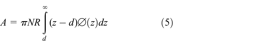
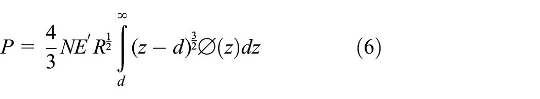
Where:

N: number of asperities
R: radius of the peaks of asperity


Schematic representation of the rough surfaces in contact.
The Young moduli and Poisson ratios of the two materials in contact are represented by
The real pressure in the elastic state is calculated by the following relation:

Where:
In the study conducted by Pederson on the shrink-fit assembly consisting of two thin cylinders as shown in Figure 3, the stresses can be calculated as follows 6 :

Internal pressure p and shrink fit interference e in a shrink fit model. 6
For inner part a ≤ r ≤ b


For outer part b ≤ r ≤ c


Simulation by finite element method
We simulate using ABAQUS to a shrink-fit assembly consisting of two cylinders of the same material (steel) with the following characteristics: E = 210 × 103, knowing that one of the two cylinders has a form defect varies in number and capacity and this is compared with the perfect case where there is no defect, Using the following boundary conditions shown in Figure 4:
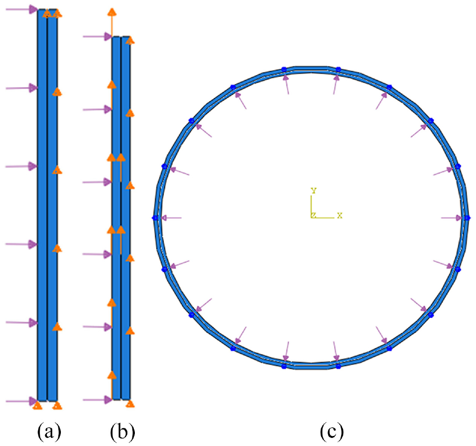
Boundary condition: (a) axial case, (b) axial case in the extraction step, and (c) radial case.
In the axial case: the inner surface of the inner cylinder subjected a pressure (P = 100 MPa) and remains in this state in the next step of extraction, While the outer surface of the outer cylinder does not move on the y axis (U2 = 0) and remains in this state in the next step. In the tension step, we move the inner cylinder according to the y axis with a value, while the outer cylinder does not move on the y axis.
In the radial case: the inner surface of the inner cylinder subjected a pressure (P = 100 MPa), while the outer surface of the outer cylinder that is attached to a reference point on the z axis does not rotate (U3 = 0). Knowing that we are dealing with only two cases, the first in which the inner surface of the inner cylinder has a form defect and the outer cylinder is perfect, and the second is in which the opposite, that is the inner surface of the outer cylinder has a form defect and the inner cylinder is perfect. This defect varies in amplitude and number. The Figures 5 and 6 show the distribution of stresses in the presence and absence of defects in the form in both cases.
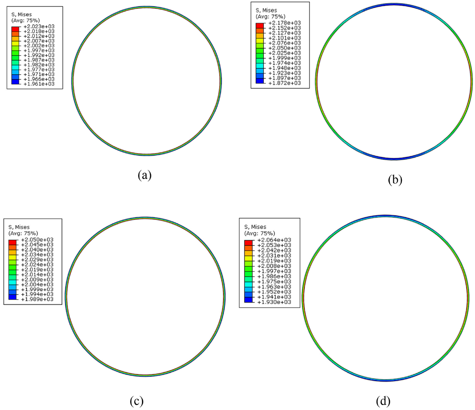
Radial distribution of von Mises stresses: (a) perfect axis, (b) axis 2 lobes, (c) 3 perfect hub, and (d) hub 2 lobes.

Axial distribution of von Mises stresses: (a) perfect axis, (b) axis 2 lobes, (c) perfect hub, and (d) hub 2 lobes.
Result and discussion
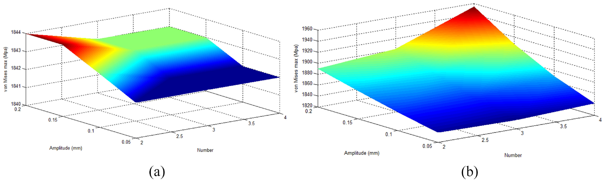
Figures 7 and 8 show the effect of the form defect on the distribution of stress, as its value increases in areas where there are no defects, and this is due to the deformation caused by pressure on the inner cylinder. As for Figures 9 to 11 they show how the form defect plays a role in the cohesion of the assembly, as the greater the amplitude and the number of form defects, the higher the maximum stress value, as well as the value of the extraction force. But when the axis has a form defect, the opposite occurs, as the stress value and the extraction force decrease with the increase in the number and amplitude of the form defect. This shows that the form defect has a positive effect if it is on the contact surface between the two cylinders, and on the contrary, the form defect has a negative effect if it is on the inner surface of the axis.
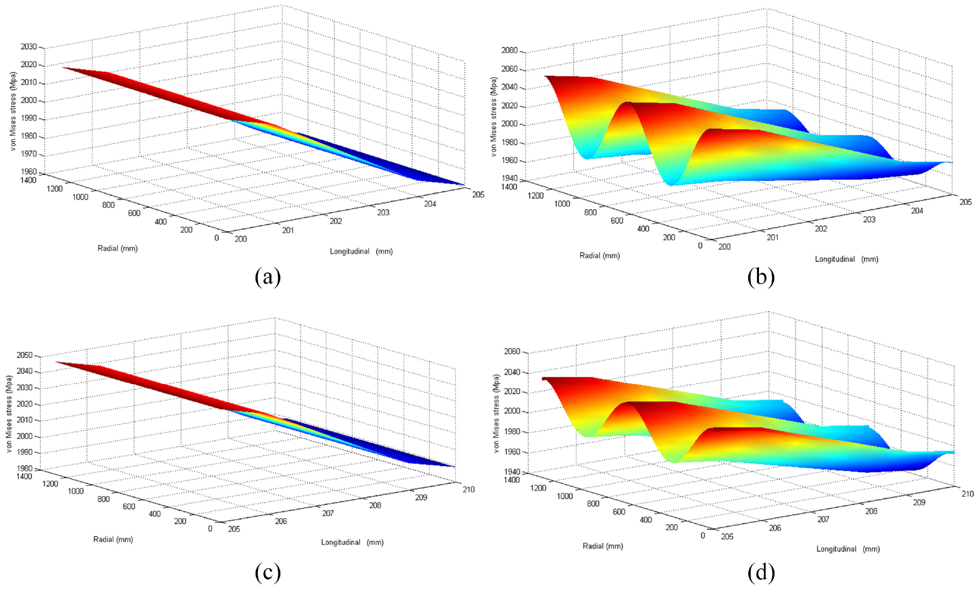
The radial and longitudinal distribution of von Mises stresses: (a) perfect axis, (b) axis 2 lobes, (c) perfect hub, and (d) hub 2 lobes.
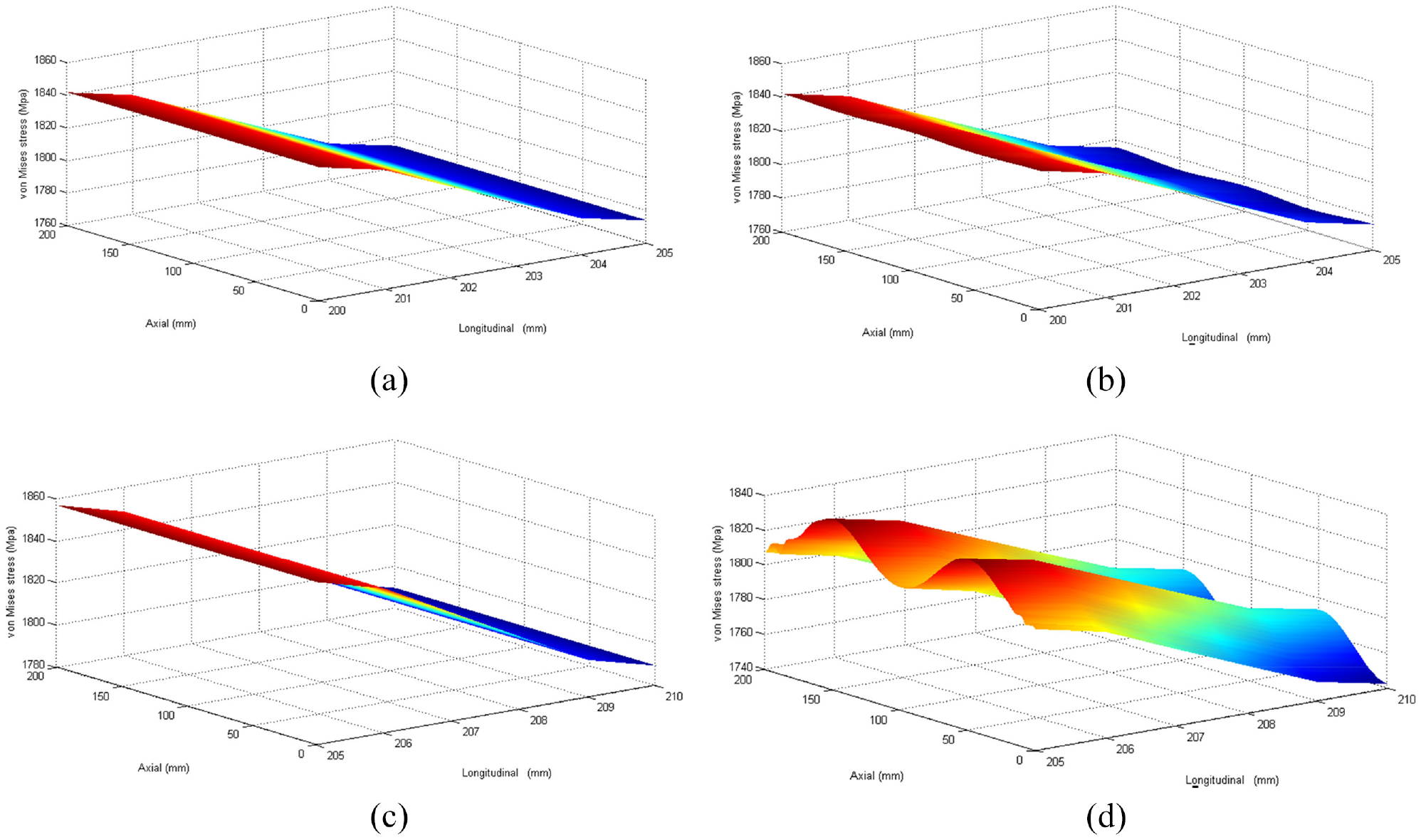
The axial and longitudinal distribution of von Mises stresses: (a) perfect axis, (b) axis 2 lobes, (c) perfect hub, and (d) hub 2 lobes.

Curve of values of von Mises maximum stresses in the radial case as a function of number and amplitude of the form defect: (a) axis is defect and (b) hub is defect.
Curve of values of von Mises maximum stresses in the axial case as a function of number and amplitude of the form defect: (a) axis is defect and (b) hub is defect.

Evolution curve of force extraction as a function of number and amplitude of the form defect in the axial case: (a) axis is defect and (b) hub is defect.
Conclusion
This study showed that in order for two thin-walled tubes not to separate at the assembly point, the form defects must be combined because they contribute to increasing the assembly resistance and facing the pressure resulting from the passage of the fluid. Rather, it requires high costs, so the presence of form defects in the contact surfaces contributes economically to the shrink-fit assembly, and on the contrary, the inner surface of the inner tube, that is the inner cylinder, must be significantly smooth. This was confirmed by the numerical simulation results, pending experimental results in future works.
Footnotes
Appendix
Handling Editor: Chenhui Liang
Author contributions
All authors contributed to the study conception and design. Material preparation, data collection, and analysis were performed by Allal Bedlaoui and Hamid Boutoutaou. The first draft of the manuscript was written by Allal Bedlaoui and all authors commented on previous versions of the manuscript. All authors read and approved the final manuscript.
Declaration of conflicting interests
The author(s) declared no potential conflicts of interest with respect to the research, authorship, and/or publication of this article.
Funding
The author(s) received no financial support for the research, authorship, and/or publication of this article.