
Abstract
Based on a model with three-degree-of-freedom, the nonlinear coupled axial-torsional vibration of drill string is numerically studied considering a modified contact model of bit-rock interaction. The effects of driving angular velocities, nominal drilling pressures, and formation stiffness on response are discussed. The simulation results show that response can be periodic, quasi-periodic or chaotic motion with the variation of system parameters. Increasing driving angular velocity is helpful to reduce the duration of sticking and even make the system stick-slip free. However, bit-bounce may occur if driving angular velocity is too large. Increasing nominal drilling pressure can cause the system to be more prone to stick-slip, but it has dampening effect on bit-bounce. The larger the formation stiffness is, the smaller the amplitude of the axial vibration response of the system is, and the driving angular velocity corresponding to the maximum amplitude of the axial vibration response is also larger, whereas the variation of the amplitude of torsional vibration is smaller. Compared with the results from two-degree-of-freedom model, the amplitude of torsional vibration of the present model is remarkable greater. Meanwhile, the present model is more prone to stick-slip than the one with two-degree-of-freedom, and it is not easy to bit bounce.
Keywords
Introduction
Nowadays, oil is an indispensable resource for society which is known as the blood of industry. The drilling system is an important part of the exploration and development of oil and gas reservoirs in petroleum engineering, as well as the exploration and development of mineral resources in mining engineering. Drilling systems can be broadly divided into two categories: percussion drilling systems and rotary drilling systems. Rotary drilling is the most common in actual oil drilling, and it is also the most cost-effective. As the core component in oil drilling engineering, the string is also the most vulnerable part of the drilling process. The failure of drill string system will bring huge cost loss to drilling engineering, so it is necessary to actively avoid the failure of drill string in the process of drilling.
In the drilling process, the overall stiffness of drill string becomes very small due to its large length to slenderness ratio (typically greater than 10,000, with ultra-deep wells usually exceeding 25,000). In the event of formation obstruction, the entire drill pipe system is extremely susceptible to vibration. The drill string is subjected to very large dynamic loads such as compression, tension, bending, and torsion. Therefore, the force and motion state of the whole drill string system is very complex and difficult to predict. For a long time, the failure of drill string caused by drill string vibration has been widely valued by many scholars. Reducing the vibration of drill string is the core problem to reduce the failure frequency of drill string and improve the service life of drill string. Therefore, it is necessary to deeply study the vibration of drill string, explore the mechanism of related vibration and fatigue failure, and form an effective control method of drill string vibration.
Lubinski and Woods were the first representatives to put forward and study the vibration theory of drill string. They published works related to drilling string vibration and proposed the differential equation of drill string stress and deformation, which provides a theoretical basis for analyzing the stress and strain of drill string. Firmie and Bailey,1,2 Dareing and Livesay 3 focused on the axial and torsional vibration of the drill string in a vertical well, conducting preliminary experiments and theoretical research. Following that, many more academics and researchers conducted several tests to investigate the vibration of drill strings. A novel mathematical model for stick-slip induced by PDC bit was developed by Richard et al. 4 The new model takes into account not just the axial and torsional modes of vibration, but also the bit-rock interaction law, as well as the cutting process and friction contact. Richard et al. 5 developed a discrete model of drill string dynamics based on the bit-rock interaction model to investigate the stick-slip vibration of a basic PDC bit. The discrete model considered the axial and torsional vibration of bit, used the function of the axial position of bit at different times to represent the cutting depth of bit, and included a delay in the motion equation throughout the cutting operation. The self-excited vibration is thought to be caused by the delay and coupling of the cutting process in the model. Zamanian 6 provided a three-degree-of-freedom model that connects torsional and axial vibration by taking into account the friction contact and cutting process of rock drilling interface, and is solved using the Euler-forward finite difference approach. According to research, the stick slip oscillation of the bit may be prevented and the vibration of the rotary table can be dampened by increasing the damping of drilling mud, bit specifications, and effectively selecting the active damping ratio. Germay 7 separated the axial-torsional coupling vibration and derived an approximate analytical solution for axial vibration in the discrete model. The analytical expression of the axial dynamic solution was used to obtain an approximate analytical expression of the velocity weakening friction law related to the physical characteristics of the system. Based on the dry friction self-excited vibration between rock and drill bit and the expression of segmented contact force and torque, Divenyi et al. 8 studied the two-degree-of-freedom model of torsional coupling nonlinear vibration of drill pipe shaft by using non-smooth dynamics theory, and describe the effect of parameters such as the length of the drill pipe and the rotating speed of the turntable on the possible bit-bounce and stick-slip motion of the drill. The axial vibration of the drill string, according to Kovalyshen, 9 is caused by the regeneration effect, whereas torsional vibration is caused by the cutting force and friction when the drill bit cuts rock. As a result, the axis-torsional coupling kinematic equation with two degrees of freedom is established. The findings suggest that axial flexibility has a key role in coupled vibration stability.
Liu et al. 10 established a two-degree of freedom axial-torsional coupling mathematical model which considered the time-lapse caused by dry friction and nonlinear contact, and discussed the influence of working parameters on the stability of drill string in three-dimensional parameter space by using the semi-discretion scheme for stability analysis. Gupta and Wahi 11 considered the regeneration effect model of tripping and stick-slip and discussed the global dynamic behavior of drill string axial-torsional coupling vibration. The cutting depth model of the drill bit was established by describing the bottom rock profile and avoid bringing hysteresis variables into the model, and obtain the coupling equation of partial differential and ordinary differential. Considering the factors such as bit-rock interaction, drilling fluid damping, and BHA eccentricity, Feng et al. 12 solved the axial-torsional-lateral coupling vibration model of drill string with six degrees of freedom by reduced-order method and the impacts of rotation speed, WOB, BHA eccentricity, and rock strength on the drill string’s dynamic properties were investigated. Gupta and Wahi 13 analyzed the factors affecting the motion stability of drill string based on an axial-torsional two-degree-of-freedom model. The results show that torsional damping is very important to the stability of drill string motion. If torsional damping is not considered, there is no stable state of drill string motion. In addition, the ratio of axial and torsional vibration natural frequencies of drill string also affects the stability of drill string movement. When the ratio of axial and torsional vibration natural frequencies is 1:1, the stability of drill string motion will be greatly improved.
Real et al. 14 proposed a new model of bit-rock interaction with time delay and applied it to analyze stick-slip vibration and stability of drill string. At high speeds and low WOB, this system promotes drill string stability, but at low speeds and high WOB, it is easy to induce stick-slip. Bit-rock interaction, contact between the drill string and the borehole wall, drilling fluid force, drill string mass eccentricity, and other coupling parameters were all taken into account by de Moraes and Savi. 15 A lumped parameter model with four degrees of freedom was established to study the axial-torsional-lateral coupling vibration of drill string. Zheng et al. 16 considered nonlinear effects related to state dependent delays caused by dry friction, contact loss and cutting force, studied the reduced-order drill string model with coupled axial-torsional dynamics, and the linearized system equation was derived. In this basis, using the continuous pole assignment method, an observer-based control scheme for time-delay systems is proposed. Based on the lumped mass technique, Chen et al. 17 established a model of axial-torsional coupling vibration of drill string with multiple degrees of freedom. The drill bit’s axial displacement is defined as a function of the drill bit’s rotation angle. The torque at the bit is defined as a function of instantaneous WOB by inserting a friction coefficient that varies with speed.
For the present, lumped parameter models are still a viable option for analyzing drill string dynamics. Therefore, in this paper, a three-degree-of-freedom lumped parameter model based on the two-degree-of-freedom model addressing the bit-rock nonlinear interaction is established. And the depth of cut is defined by using a function containing a sinusoidal variation. The mathematical model is solved by ode45 in MATLAB to derive the effects of the drive angular velocity, nominal drilling pressure, and formation stiffness on the system response. The reference values of the operating parameters for the system in case of bit-bounce or stick-skip are given, and the results are compared to those of the two-degree-of-freedom model.
Dynamical modeling
Gupta and Wahi 13 simplified the system of drill string and established a two-degree-of freedom model system. Based on their dynamic model, another degree of freedom in torsional direction is added in this paper. Therefore, the torsion is divided into two-degree-of-freedom (2-DOF), the axial is still simplified to one degree of freedom, and a model with three-degree-of-freedom (3-DOF) is established. The physical model of drill string is shown in Figure 1. According to the previous work results, the deformation of the drill string in the torsional direction is relatively large, so simplifying it as two degrees of freedom is more helpful to describe the torsional deformation of the system.
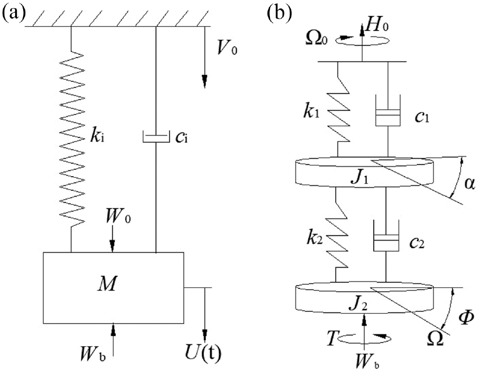
Mechanical model of drill strings: (a) axial mechanical model and (b) torsional mechanical model.
For this study, it is assumed that (i) the drill string is vertical to the wellbore, ignoring the contact between the drill pipe and the shaft wall and ignoring the lateral movement of the drill string; (ii) the tip of the drill string is driven at a constant axial velocity
In this paper, drill strings are modeled as spring-mass systems with viscous damping as shown in Figure 1 where (a) and (b) are used to illustrate axial and torsional vibration of drill strings. ki and ci represent axial stiffness and damping. M represents the mass of drill string including BHA. J1 represents half the moment of inertia of the drill string, and J2 represents the sum of the half moment of inertia of the drill string and the moment of inertia of the drill bit. k1 and k2 represent the torsional stiffness corresponding to half length of drill strings. c1 and c2 represent torsional damping respectively.
According to the physical model, the equations of drill string system can be written as 6 :

where
Since the contact between the drill bit and rock forms a leaf surface profile, which can be defined by the profile with sinusoidal variation, the expression of cutting depth

where
The coupling between axial vibration and torsional vibration of drill string is completed by the interaction between bit and formation, and the expression of

where
The expression of

where the friction behavior between the bit and formation

where

where

Dynamical simulations
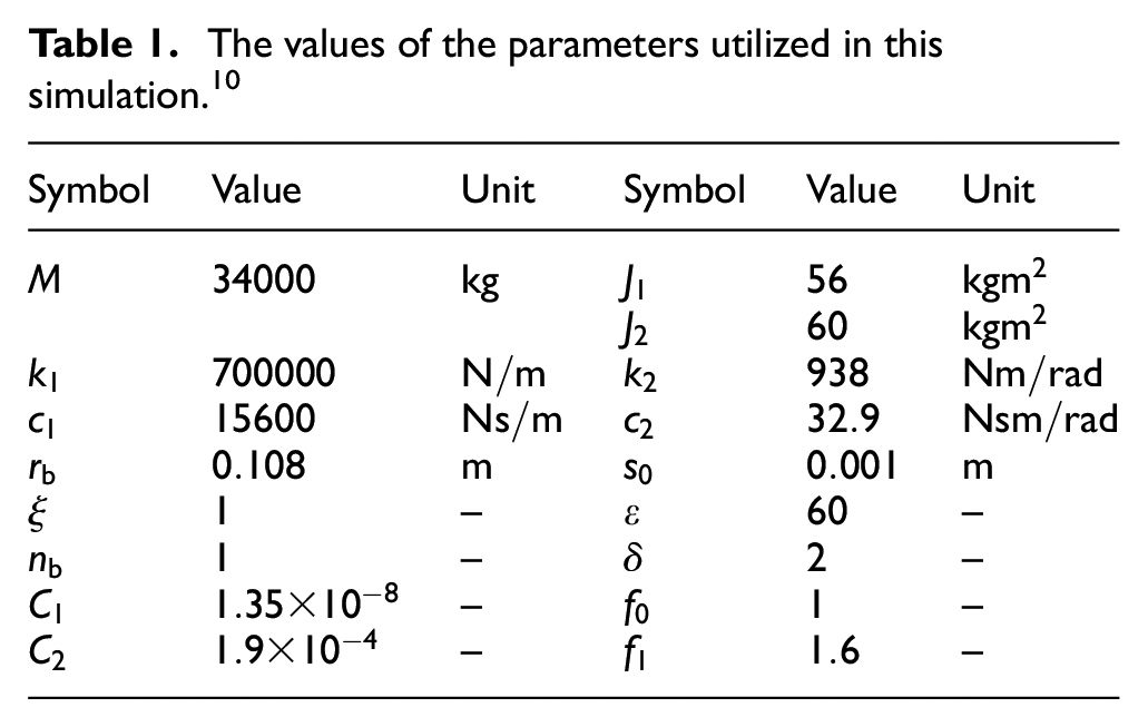
Generally speaking, the working parameters in drilling engineering include the rotary table driving angular speed, top hook load, feed rate, etc. During drilling, different working conditions can be dealt with by changing the input working parameters. The harmful movement during drilling can be controlled to make the drilling work efficient and safe. Table 1 lists the values of the parameters utilized in this simulation.
The values of the parameters utilized in this simulation. 10
Influence of driving angular velocity
When the drill string system works, the top drive system drives the drill pipe to rotate through its own rotation and continues to transmit torque downward to BHA (bottom hole assembly), so as to make the bit rotate and drill the rock stratum. Because the drilling process is very complex, the selection of appropriate driving angular velocity has a vital impact on the drilling situation of the whole system.
To investigate the effect of driving angular velocity, the variation of amplitude with it and bifurcation diagram are given as Figures 2 and 3 respectively.

Effect of driving angular velocity on system response,

Bifurcation diagram of system response, blue: 2-DOF, red: 3-DOF,
It can be seen from Figure 2 that the overall trend of the curves obtained by the two models is quite consistent. When the driving angular velocity is in the interval [0, 14.2] rad/s, the amplitude of three degrees of freedom is slightly greater than that of two degrees of freedom. The curve corresponding to the model with 3-DOF reaches the first and second peaks when the rotary table driving angular velocity is 14.2 and 19.3 rad/s, and the peak values are 3.065 × 10⁻³ m and 2.836 × 10⁻³ m respectively. For the model with 2-DOF the peak values are 2.179 × 10⁻³ m and 2.629 × 10⁻³ m at 13.1 and 19.3 rad/s respectively. From Figure 3, it is shown that the response is chaotic for lower angular velocity and simple periodic motion for higher angular velocity.
Figures 4 and 5 show the time history and phase trajectory of the three degree of freedom model respectively to further analyze the specific motion state of the drill string under different working parameters.

Time history of system response: (a) time history of axial relative displacement, (b) time history of relative angular displacement, (c) time history of axial relative velocity, (d) time history of relative angular velocity, and (e) absolute angular velocity curve.
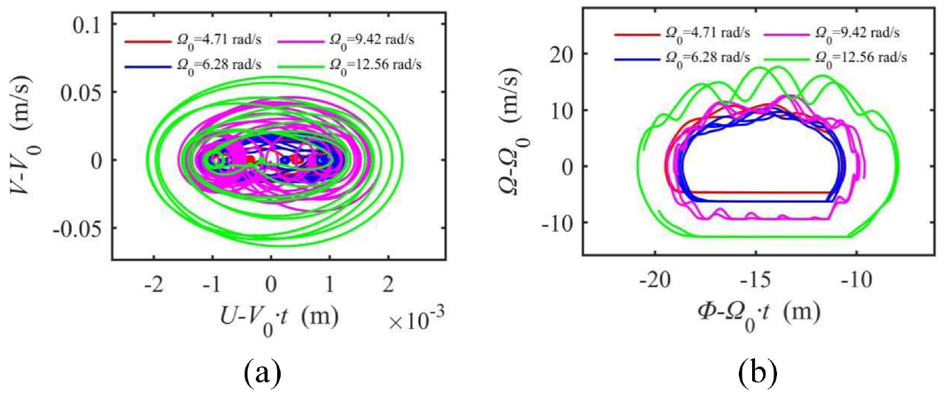
Phase trajectory: (a) phase trajectory of axial vibration and (b) phase trajectory of torsional vibration.
The relative displacement, relative velocity, and phase trajectory under the four driving angular velocities are irregular. It is also verified that the response curves and bifurcation diagrams of axial vibration in Figure 3 are chaotic in the interval [0, 14.2] rad/s. With increasing angular velocity, the amplitude of relative displacement and relative velocity increases at the same time. The time history curve of relative angular velocity grows more complicated than that of relative angular displacement. In this interval, the relative angular velocity curve occasionally coincides with
Duration of stick state under different driving angular velocities.

When the driving angular velocity is in the range of [14.3, 19.2] and [19.3, 27] rad/s, the corresponding results are as shown in Figures 6 to 9 respectively which mean the response is periodic motion.
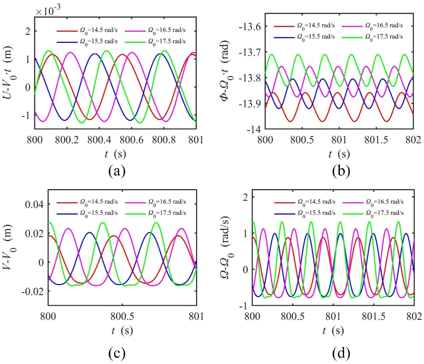
Time history of system response: (a) time history of axial relative displacement, (b) time history of relative angular displacement, (c) time history of axial relative velocity, and (d) time history of relative angular velocity.
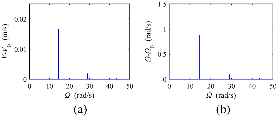
Spectrum of axial and torsional vibration,

Time history of system response under four angular velocities: (a) time history of axial relative displacement, (b) time history of relative angular displacement, (c) time history of axial relative velocity, and (d) time history of relative angular velocity.

Spectrum of axial and torsional vibration,
It can be found from Figures 6 to 9 that both the relative axial and torsional vibrations are simple periodic motions. And the amplitude of the corresponding time history in Figure 8 is larger than that in Figure 6. From the Figures 7 and 9, it is shown that the periodic responses consist of more discrete frequencies around which the energy is concentrated. In Figure 9, the higher frequency is twice the lower frequency related to driving angular velocity. However, the highest frequency component in Figure 7 is three times the first one which is consistent with the driving angular velocity.
In addition, the response amplitude increases with the increase of the driving angular velocity except the relative angular displacement, and the absolute values of averages of relative angular displacements decrease with the increase of the driving angular velocity.
When the driving angular velocity is in the range of [27.1, 60] rad/s, the result curves are as shown in Figure 10 which means that bit-bounce occurs since Wb is zero sometimes.

Time history of WOB under four angular velocities.
Influence of nominal drilling pressure
In this section, the effect of W0 is investigated. The drive angular velocity is chosen in the range of [0, 25] rad/s and the formation stiffness is 50 MN/m.
The amplitude curves of the system response with nominal drilling pressure are given in Figure 11 with the results for both models. The overall trend is the same for the two models with 2 and 3 DOF. When the nominal drilling pressure is in the range of [0, 200] kN, the axial vibration relative displacement and absolute velocity curve of three degrees of freedom are very similar to that of two degrees of freedom. When the nominal drilling pressure is greater than 200 kN, the vibration amplitude curve of three degrees of freedom is greater than that of two degrees of freedom as a whole. Within the range of simulation parameters, the amplitude curves of three degrees of freedom are above the amplitude curves of two degrees of freedom. Moreover, as the nominal drilling pressure is increased, the difference between the amplitude of three degrees of freedom and two degrees of freedom grows.

Effect of nominal drilling pressure on system response,
The following time histories are provided for the three-degree-of-freedom model to better examine the vibration of drill string.
The time history curves under six different nominal drilling pressures are provided in Figure 12 to explore the law of nominal drilling pressure. Under six nominal drilling pressures, the time history curves of relative displacement and velocity of axial vibration are irregular. However the amplitude of axial relative displacement and relative velocity vibration increases with increasing of W0. The absolute value of the relative displacement and absolute angular velocity of torsional vibration increases as W0 increases.

Time history of different nominal drilling pressure,
The absolute angular velocity curve of torsional vibration shows stick-slip under six kinds of nominal drilling pressure. The amplitude of absolute angular velocity curve increases with the increase of W0, and the greater of W0 is, the longer the duration of stick state is, as shown in Table 3. Therefore, in order to reduce the stick-slip phenomenon, it can be considered to appropriately reduce the value of nominal drilling pressure.
Duration of stick state under different nominal drilling pressure.

Figure 13 shows time histories at driving angular velocity values of 9.42 and 15.7 rad/s to study the general law of the influence of W0 on the system. When W0 increases, axial vibration relative displacement and torsional vibration relative angular displacement increase. In Figure 13(e) and (f), the absolute angular velocity time history shows that stick-slip no longer occurs at 15.7 rad/s corresponding to the first four W0. This proves that increasing the driving angular velocity is helpful to reduce the occurrence of stick-slip. However, stick-slip still occurs when W0 is 200 or 300 kN. Therefore, the greater W0 is, the greater the driving angular velocity to overcome stick-slip is, and the easier stick-slip motion takes place.
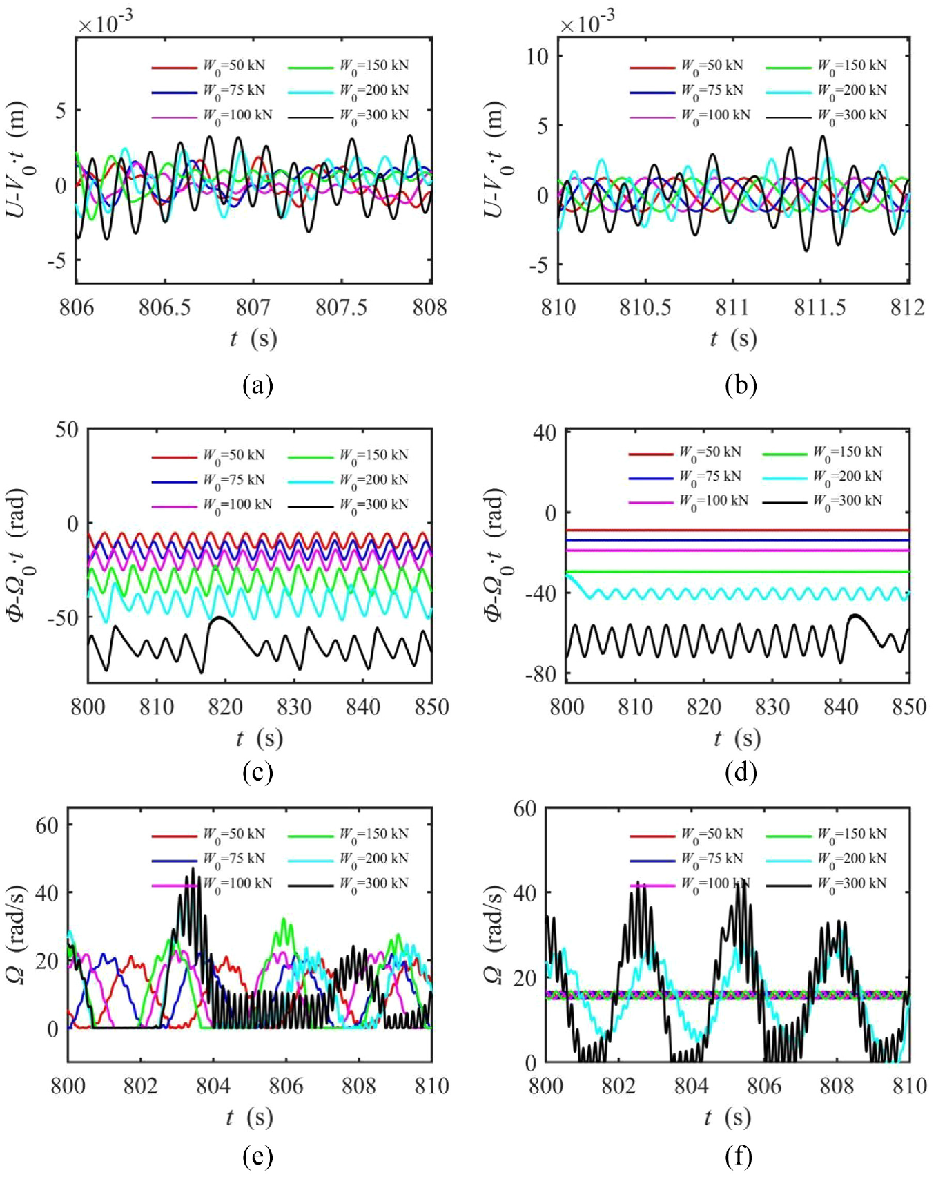
Time history under different W0: (a)
Simulation results indicate that stick-slip occurs at low speeds. However, with the variation of W0, the critical driving angular velocity also changes when there is no stick-slip. Table 4 shows the driving angular velocity when the stick-slip of the system no longer occurs. Figure 14 presents the time history curves of stick-slip and no stick-slip when W0 is 50 kN. At the same time, the results are compared with the corresponding results of two degrees of freedom. It is found that with the increase of W0, the corresponding driving angular velocity increases when the stick-slip motion of the system no longer occurs. That is, the range of driving angular velocity increases when stick-slip occur for small driving angular velocity. Compared with the results of two degrees of freedom, it is found that the critical driving angular velocity of stick-slip in the three degrees of freedom model is greater than that of two degrees of freedom model. Table 5 compares the critical driving angular velocity under different W0. Figure 15 shows the time history curve of the system when drilling jump starts to occur. It is found that the three degrees of freedom model is less prone to bit bounce than the two degrees of freedom model.
Critical driving angular velocity when there is no longer stick-slip under different W0.


Critical driving angular velocity at which stick-slip occurs,
Critical driving angular velocity when bit-bounce occurs under different W0.


Critical driving angular velocity when bit bounce occurs,
Influence of formation stiffness
In this section, the variation of system response with driving angular velocity under three formation stiffness is analyzed.
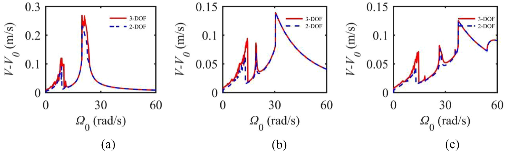
For three kinds of formation stiffness, the responses of the two models are given when angular velocity are varied are given Figures 16 to 21. According to the response curves, there is no difference in the overall change trend for the two models. For the results of axial relative displacement, relative velocity, and absolute velocity, the main difference is the peak value near the resonance frequency of the torsional degree of freedom and the frequency when the peak value occurs. For the three-degree-of-freedom model, a slightly higher value is obtained than one with the two-degree-of-freedom model. When the driving angle speed is large, the curves obtained from the two models are almost the same. However, comparing the results of relative angular displacement, angular velocity, and absolute velocity of torsional degrees of freedom, it can be seen that the amplitude of three degrees of freedom model is significantly larger than one of two degrees of freedom model. In addition, as the numerical simulation results of three formation stiffness of the three-degree-of-freedom model are compared, it can be seen that the amplitudes of relative displacement, relative velocity, and absolute velocity of the axial vibration decrease as the formation stiffness increases. It can be seen from Figures 16–18 that there are two peaks when the formation stiffness is 15 MN/m, and three peaks when the formation stiffness is 50 and 100 MN/m. The driving angular velocity corresponding to the peak also increase with the increase of formation stiffness. Formation stiffness has little effect on the amplitude of relative angular displacements, relative angular speeds, and absolute angular speeds of torsional vibrations. And it has little effect on the angular velocity corresponding to the peak.

The effect of driving angular velocity on axial relative displacement: (a)
The effect of driving angular velocity on axial relative velocity: (a)
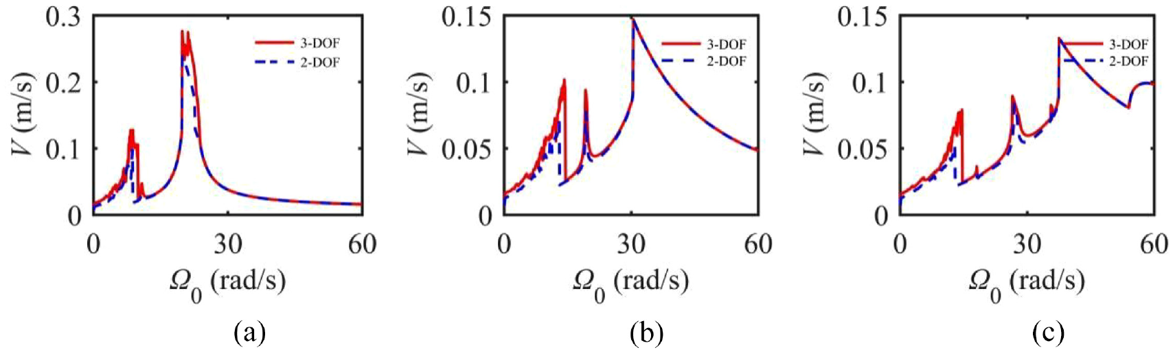
The effect of driving angular velocity on axial absolute velocity: (a)

The effect of driving angular velocity on torsional relative angular displacement: (a)

The effect of driving angular velocity on torsional relative angular velocity: (a)

The effect of driving angular velocity on torsional absolute angular velocity: (a)
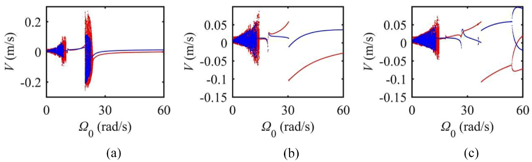
The bifurcation diagram corresponding to the amplitude curve of the system response are given as shown in Figures 22 to 27. When the formation stiffness is 15 MN/m, there are two chaotic regions in the system. When the formation stiffness is 50 MN/m, there is only one chaotic region in the system, and in the rest regions, the respond are periodic. However, the system has period doubling bifurcation when the formation stiffness is 100 MN/m.

Bifurcation diagram of relative displacement varying, blue: 2-DOF, red: 3-DOF: (a)

Bifurcation diagram of relative velocity, blue: 2-DOF, red: 3-DOF: (a)
Bifurcation diagram of absolute velocity, blue: 2-DOF, red: 3-DOF: (a)

Bifurcation diagram of relative angular displacement, blue: 2-DOF, red: 3-DOF: (a)

Bifurcation diagram of relative angular velocity, blue: 2-DOF, red: 3-DOF: (a)

Bifurcation diagram of absolute angular velocity, blue: 2-DOF, red: 3-DOF: (a)
Conclusion
Based on a modified drill-rock interaction model and a three-degree-of-freedom governing equation, coupled axial-torsional nonlinear vibration of drill strings is examined numerically in this paper. The bifurcation diagram, phase trajectory, time history, and frequency spectrum are used to illustrate the effect of parameters such as driving angular velocity, formation stiffness, and nominal drilling pressure on response based on Runge-Kutta method for numerical integration. The results obtained by the present model are compared with those of the two-degree-of-freedom model.
According to the simulations, the following conclusion can be summarized. The stick-slip phenomenon can be effectively suppressed by appropriately increasing driving angular velocity. However, excessive driving angular velocity can lead to increase of the axial vibration amplitude and induce bit-bounce phenomenon. With increase in nominal drilling pressure, drill strings become more likely to be damaged as the result of increase in relative angular displacement which means large torsional deformation. At the same time, the larger the nominal drilling pressure is, the longer the duration of stick is. The increase of the formation stiffness result in smaller amplitude of the axial vibration and larger driving angular velocity corresponding to the peak of amplitudes. However, the variation of formation stiffness has less effect on the amplitude of the torsional vibration.
By comparing with the results of the model with two degrees of freedom, it is found that the critical driving angular velocity when there is no longer stick-slip motion is greater. The driving angular velocity when bit-bounce began to appear is also greater than that of the two-degree-of-freedom model. In other words, the three-degree-of-freedom model is more prone to stick-slip than the two-degree-of-freedom model, but it is less prone to bit bounce.
Footnotes
Acknowledgements
The authors of this paper would like to express their sincere thanks to the reviewers for acceptance to review this paper.
Handling Editor: Chenhui Liang
Declaration of conflicting interests
The author(s) declared no potential conflicts of interest with respect to the research, authorship, and/or publication of this article.
Funding
The author(s) disclosed receipt of the following financial support for the research, authorship, and/or publication of this article: This research was supported by the National Natural Science Foundation of China (Grant No. 11972145).