
Abstract
In this paper, the thermomechanical characteristics of microturbine bearing during the process of bearing performance decay due to abrasive particles are theoretically and experimentally researched, such as contact characteristic, temperature characteristics, and stiffness characteristic, are illustrated. The results is that the evolution law of contact deformation and contact stiffness over the whole life of bearing is the same, whose amplitude is slightly different. The curve shape and amplitude of contact angular between ball and outer/inner ring has the obvious diversity.
Keywords
Introduction
Under operation of angular contact ball bearing, there is abrasive wear in bearing as lubrication grease or lubrication oil is polluted. 1 For instance, abrasive particles owing to wear of sealed structure material and coating gradually accumulate inside the bearing once the particles enter into lubrication media, which results in abrasive wear amongst rolling element, raceway and cage. It further induces the surface scratch or spall of the rolling bearing material, which leads to plow-shaped scratch or pit on the contact surface, broadens the working gap of bearing, and changes the contact surface topography of bearing parts. In severe cases, the contact surface temperature increases so greatly that scuffing occurs. 2 The severity of abrasive wear is affected by quantity, shape, size, and hardness of abrasive particles.2–6
Non-contact sealing structure and its coating are prone to wear as microturbine bearing is running with high speed, these spalling particles inevitably enter the bearing lubrication cavity, resulting in the variation of bearing vibration characteristic, and the deterioration of bearing performance, which seriously endangers the safety and stable operation of microturbine.
Nowadays, there is a small quantity of papers on abrasive wear, in particular, the study of bearing performance degradation and vibration increment induced by abrasive particles is rarely reported.
The existing papers are focus on the wear rate and temperature rise 7 on the bearing material surface originated by lubricant borne particles, including debris material8–10 and size. 3 Besides, it is obvious that type and size of particles have influence on shortening fatigue life of bearing. 11 Besides, abrasive wear also has an effect on the vibration behavior of bearing, people have learned that bearing condition monitor is effective by jointly analyzing particle quantity and vibration signal.12–15 The study on related questions has drawn high attention from scholars, whose practicability and depth are not enough. There is few paper on vibration and performance evolution mechanism affected by abrasive wear.
In this paper, the evolution rules of bearing contact characteristics, temperature characteristics, and stiffness characteristics are discussed based on combining microturbine bearing response test affected by abrasive particles and bearing dynamic characteristics analysis. The test simulating bearing performance degradation under abrasive particles is conducted, whose temperature data is employed to validate the mechanical-thermal coupling model that is established based on bearing quasi-statics and elastohydrodynamic lubrication theory.
The remainder of the article is illustrated as follows: the simulation principle for abrasive wear and method are depicted in Section 2. In Section 3, test rig for microturbine bearing performance simulation test under abrasive particles is illustrated. In Section 4, the results are analyzed and discussed. Conclusions are made in Section 5.
Abrasive wear simulation principle and method
As bearing is running under abrasive particles, the surface of ball and outer/inner ring is free of scratch if the size of abrasive particles is less than the minimum oil film thickness, however, there is plow-shaped graze or pit as the larger size of particles penetrate the oil film, which results in the contact between particles and surface of ball or ring, the expansion of bearing working clearance, and the change of bearing parts surface topography, moreover, the fluctuation of bearing vibration occurs. Thus, the lubrication oil viscosity descends with the increment of contact surface temperature induced by aggravation of friction between the mating parts, which further accelerates the abrasive wear of local contact surface and makes the bearing temperature have a sharp rise. There is scuffing if the temperature of contact surface exceeds the critical value, which causes the outstanding increment of bearing vibration. The sketch map of abrasive particles is depicted in Figure 1.

Schematic diagram of wear due to abrasive particle.
The abrasive wear simulation test rig of microturbine bearing is depicted in Figure 2, which is realized by filling the sand into the gap between inner ring and outer ring. By this way, the sand is sealed in bearing cavity as bearing is running, thus, the bearing life is significantly shorten.

Sand location and end cover: (a) Sketch map and (b) entity graph.
Based on the analysis model of bearing mechanism-thermal characteristics, for obtaining the satisfactory calculation results, the friction moment of different stage during the operation process of bearing is obtained by adopting “heat contribution factor” to adjust the load friction moment and viscosity friction moment proposed by Palmgren, 16 which is utilized to describe the severity and location of abrasive wear in the operation process of bearing. The expression is illustrated as follows;

where,
Node thermal network model of house-bearing-shaft system employed in the simulation test is illustrated in Figure 3, which totally has 17 nodes. Thereinto, seven nodes on bearing body, four nodes on shaft, and one node is ambient environment.

Node thermal network model.
Test rig
The bearing performance degradation simulation test rig and signal acquisition used in this paper is firstly introduced in literature, 17 the specific description is as follows.
Performance decay simulation test rig
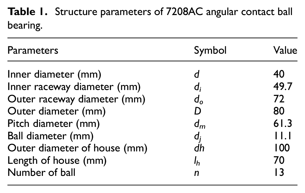
As described in Figure 4, the multi-sensor signals during the process of bearing performance degradation induced by abrasive particles are achieved taking advantage of microturbine bearing-rotor system test rig as the rotation speed is 2400 r/min, whose concrete structure is 1-0-1 meaning that the disk is between bearing 1 and bearing 2. Among which, bearing 1 is the tested bearing, another one is taken as contrast bearing, they are fixed at C and D of cylinder-shaped house by employing end cap. The designation of bearing is 7208AC angular contact ball bearing, whose structure parameters are depicted in Table 1. The house is mounted to pedestal with bolts at the middle of house. The rotor is driven by an electric machine in order to obtain different speed.

Test equipment: (1) pedestal, (2) bearing seat, (3, 9) end cover, (4) shaft, (5, 8) disk, (6, 7) bearing, (10, 11) drum, (12) coupling, and (13) electric machine. (a) Test rig and (b) rotor structure.
Structure parameters of 7208AC angular contact ball bearing.
Signal acquisition system
The test is end as there is a failure or the vibration obviously changes, which explains that the bearing is out of service. The detailed introduction of sensors used in the test is presented in Figure 5. Sensor 1, 2, and 5 are used to acquire the shaft vibration by adopting RP6606XL eddy current sensor, sensor 3 and 4 are utilized to consecutively record the bearing vibration via CAYD115V-100A IEPE accelerometer, in addition, the house temperature is obtained by 3 thermal couples expressing themselves in the form of even distribution along the periphery direction of house surface. Among which, the thermal couple numbered as 6 is placed in the location deviating from the vertical radial direction with 15°. It can stop the disturbance to the bearing vibration signal collection. Furthermore, the equipment (NI cDAQ-9174) and NI LabVIEW program are introduced aiming at storage and on-line demonstration of signals. The sampling frequency of signals is 25.6 Hz of vibration signal and 2 Hz of temperature, respectively. Signal record lasts 20 s.

Location of sensors: (1) eddy current sensor 1, (2) eddy current sensor 2, (3) acceleration sensor 1, (4) acceleration sensor 2, (5) eddy current sensor 1, (6) thermal couple 1, (7) thermal couple 2, and (8) thermal couple 3.
After the sand is filled into bearing, the test rig begins to be in motion with rotation speed keeps at 2400 r/min under a spot of lubrication grease, the cooling effect of the oil is ignored. The total quantity of particles is 2 g. The test totally lasts 11 h.
Results and discussion
By modifying the “heat contribution factor,” the calculation value of house temperature is obtained, which is employed to make a comparison with test value of house temperature. The result is illustrated in Figure 6.

Comparison between test result and calculation result of house temperature due to abrasive and wear.
As shown in Figure 6, the result of comparing average temperature of three test points on the house and calculation value illustrates that temperature test value agrees with calculation value.
Contact characteristic, temperature characteristic, and stiffness characteristic in the different phase during bearing performance decays under abrasive particles are depicted as follows.
Contact characteristic evolution rule analysis
As bearing is running, the increment of particles quantity leads to the transformation of bearing surface roughness, which exacerbates heat production of the mating parts and results in expansion of the bearing parts in different degrees. Thus, the contact characteristics of the mating parts have various change, including contact deformation, contact angular, and contact stiffness.
As illustrated in Figure 7, the evolution rule of contact deformation between ball and outer/inner ring is consistent, whose amplitudes are basically equal. During the whole life of bearing, the shape of curves changes focusing on the location from 150° to 240°. The curve shape expresses itself in the form of convex “D” at 0–2 h, then “D” at 3 h, finally, it becomes concave “D.”
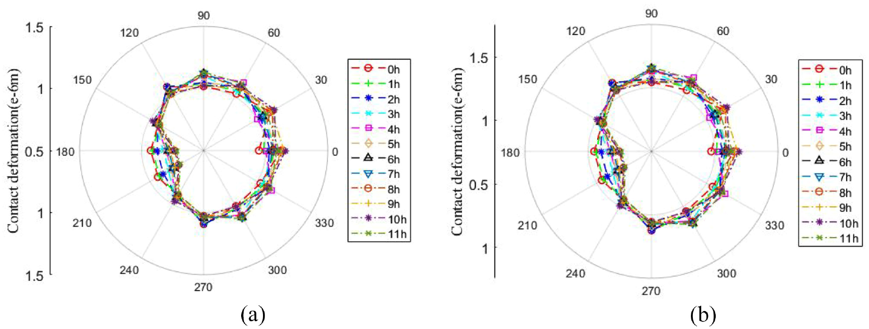
Contact deformation: (a) region between ball and outer ring and (b) region between ball and inner ring.
Figure 8 depicts the evolution law of contact angular between ball and outer/inner ring. It is obvious that the shape and amplitude of them are evidently different. The curve shape of contact angular between ball and outer ring is similar to “D” with one end compressed, whose amplitude varies in the scope of 180°–210° and reaches minimum value at 9 h. The curve shape of contact angular between ball and inner ring performs itself as “D,” whose amplitude fluctuates ranging from 150° to 240° and reaches maximum value at 9 h.

Contact angular: (a) region between ball and outer ring and (b) region between ball and inner ring.
As illustrated in Figure 9, the evolvement curve of contact stiffness between ball and outer/inner ring during the whole life of bearing is identical, but the shape is complex and changeable. The amplitude of contact stiffness between ball and outer ring is overall higher than that between ball and inner ring. The region where the amplitude has a complicated and evident diversification is 330°–60°. Moreover, the amplitude in the scope of 180°–220° is the minimum value in the process of bearing performance decay (except 9 h).
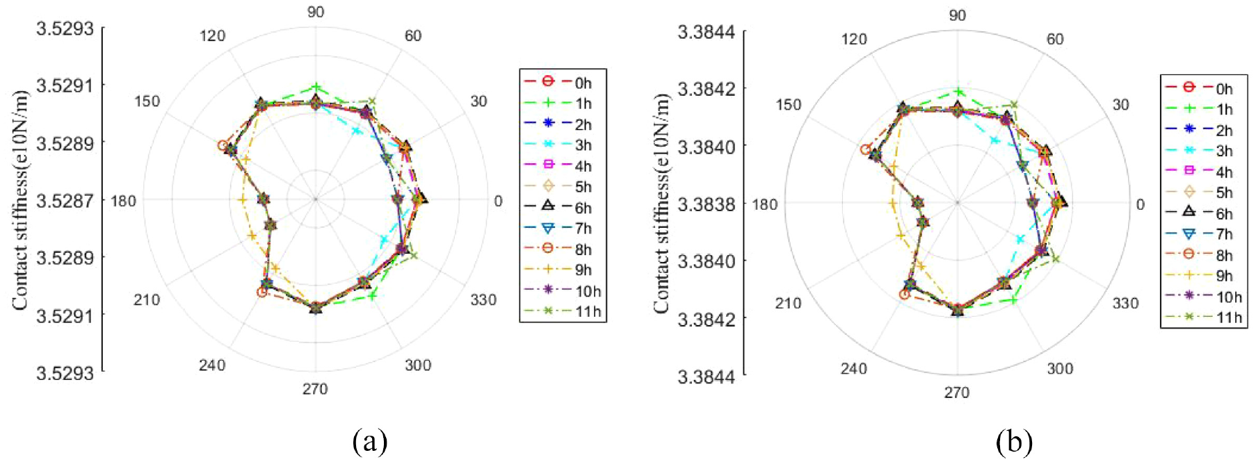
Contact stiffness: (a) region between ball and outer ring and (b) region between ball and inner ring.
Temperature characteristic evolution rule analysis
Node temperature calculation results of house-bearing-shaft system influenced by abrasive particles are demonstrated in Figure 10. Each node temperature significantly increases at first 1 h, then decreases to minimum value at 5 h, the temperature slightly goes up after stabilization for 1 h. The temperature of contact zone between ball and inner ring is basically equal to that of inner ring, which is the maximum value. The temperature of outer ring and that of shaft right end are roughly identical. However, the temperature of contact zone between ball and outer ring is somewhat higher than that of outer ring.

The temperature evolution curve of bearing system nodes over whole lifetime.
The friction moment of the mating parts during the whole life of bearing is illustrated in Figure 11. The moments are the friction moment due to elastic hysteresis
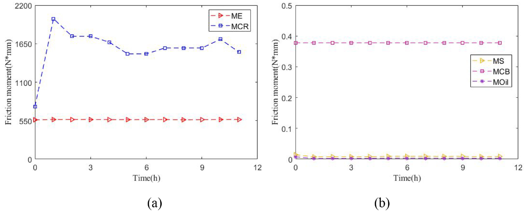
Friction moment. ME: friction moment due to elastic hysteresis; MCR: friction moment due to contact between cage and inner ring guide face; MS: friction moment due to spin-sliding motion; MCB: friction moment due to contact between ball and cage; MOil: friction moment due to oil film viscosity loss.
The corresponding “heat contribution factor” at the different stage during the whole life of bearing affected by abrasive particles is depicted in Table 2. It is obvious that
Thermal contribution factor.

The evolution rule of radial clearance and displacement during the whole life of bearing is shown in Figure 12, which is mainly divided into two stages: 0–1 and 1–11 h. It shows that the clearance variation trend has negative correlation with the temperature evolution rule, however, the relationship between displacement curve and temperature evolution rule is positive. The value of clearance is negative, which rapidly decreases at 0–1 h, then firstly increases and undulately reduces. The displacement test value and calculation value are mildly rise up at 0–1 h, the calculation value keeps steady at the rest of time. The test value begins to evidently fluctuant after stabilizing for a while, whose value is higher than that of calculation value. It because that the calculation result without considering temperature variation has effect on shaft, house, as well as fit between shaft and inner ring, house and outer ring.

Radial clearance and displacement: (a) radial clearance and (b) radial displacement.
Oil film thickness and stiffness evolution ruleanalysis
The oil film thickness, oil film stiffness and bearing dynamic stiffness over the whole life of bearing are illustrated from Figures 13 to 15. As described in Figure 13, the variation tendency of oil film thickness between ball and outer/inner ring is homology, which behaves themselves as the concentric circle. The amplitude of oil film thickness is the maximum value at 0 h, but it reaches the minimum value at 1 h. The oil film thickness value of contact region between ball and outer ring is always higher than that of contact region between ball and inner ring.
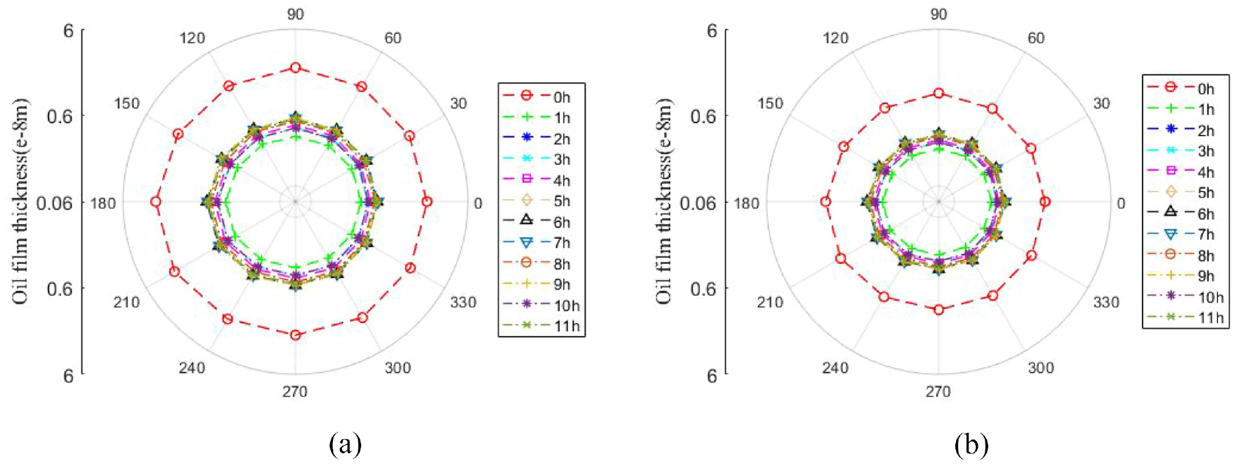
Oil film thickness: (a) region between ball and outer ring and (b) region between ball and inner ring.
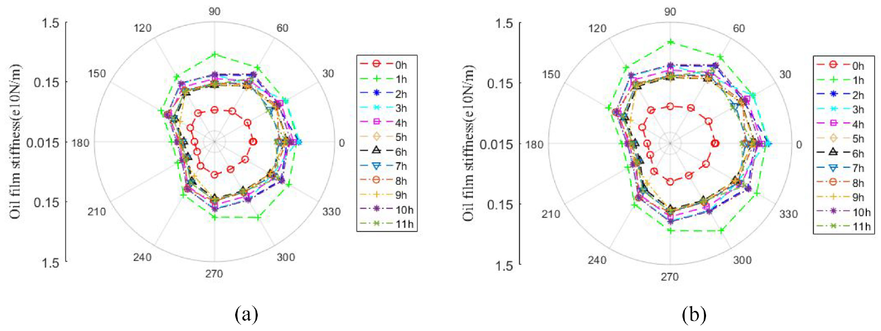
Oil film stiffness: (a) region between ball and outer ring and (b) region between ball and inner ring.

Stiffness.
As depicted in Figure 14, the oil film stiffness of contact zone between ball and outer/inner is uniform, whose shape is the concentric “D,” there is a little difference in amplitude. Within the 360°, the oil film stiffness is the minimum at 0 h, then it goes up to the maximum at 1 h, the areas with a significant change are 60°–120° and 270°–330°.
The integral dynamic stiffness along radial and axial direction during the service process of bearing is illustrated in Figure 15. Radial stiffness variation tendency is consistent with temperature, but the axial stiffness significantly rises up at initial stage, then maintains stable, the amplitude of stiffness along two direction has obvious difference.
Conclusion
In this paper, the thermomechanical characteristics of microturbine bearing during its performance degradation process under abrasive particles are studied. The conclusions are made as follows:
The evolution law of contact deformation and contact stiffness over the whole life of bearing is the same, whose amplitude is slightly different. The curve shape and amplitude of contact angular between ball and outer/inner ring has the obvious diversity.
Over the whole life of bearing,
The variation curve of bearing dynamic stiffness agrees with that of temperature in general, in addition, radial stiffness is overall larger than axial stiffness.
Footnotes
Handling Editor: Chenhui Liang
Declaration of conflicting interests
The author(s) declared no potential conflicts of interest with respect to the research, authorship, and/or publication of this article.
Funding
The author(s) disclosed receipt of the following financial support for the research, authorship, and/or publication of this article: This research work was supported by the National Key R&D Program of China (Grant No. 2018YFB2000300).