
Abstract
In order to avoid the hard landing on the uneven ground, several robotic landing gears of the rotorcraft are designed. In previous studies, most literature focuses on the control methods of the robotic landing gears. There has been very little research on the dynamic model of the rotorcraft with the robotic landing gears in the landing process. In this work, based on the Lagrangian formulation, the dynamic model of the rotorcraft considering different parameters in the landing process is derived, where the angle of the slope of the uneven ground and the angle of the attack of the rotorcraft are considered. Then an approach is presented to determine the bounds of the dynamic response of the rotorcraft with uncertainties parameters. The results of numerical examples show that in order to maintain the safety, the robotic landing gear of the rotorcraft would be controlled to adjust the condition of the ground, while the initial velocities are restricted to be less than certain value; the large deviations of the landing parameters would may resulted in an overload of the rotorcraft.
Keywords
Introduction
It is well known that the mobility and flexibility are the principal advantages of rotorcrafts, compared to the fixedwing-aircraft. 1 The rotorcrafts are invaluable tools in many fields such as the emergency rescue missions, 2 the exploration of the disaster areas 3 , or the mountainous environments. The crucial virtue of rotorcrafts is their vertical takeoff and landing ability. A classical case which is frequently encountered is that when a disaster is happening, the environment is harmful or dangerous to persons. The disaster is far away from where the rotorcrafts can take off. The rotorcrafts need to carry out a long distance flight to explore the disaster or the emergency situation. Because of the limitation of the power of the battery, the rotorcrafts cannot continually hover over for a long time; otherwise the rotorcrafts would not be capable of leaving the disaster area. The rotorcrafts would change the spots to get entire information with several landing and takeoff processes. In this situation, the rotorcrafts are unavoidable to land on the uneven terrain. It is very difficult for the rotorcrafts to land on the uneven surface safely, which would result in the behavior of the dynamic rollover 4 or the hard landing. 5 The hard landing, an unacceptable way under normal conditions, means that an aircraft relatively rapidly descents and drops on the ground with a high speed, usually resulting in serious fuselage damage, structural failure, or cargo damage. Therefore, the autonomous landing of the rotorcrafts on the uneven surface is a demanding problem.
In order to avoid the dynamic rollover or the hard landing of the rotorcrafts, several robotic landing gears are proposed by researchers, 6 which would be controlled to adjust the condition of the ground to insure the safe landing. In 2015, a robotic landing gear for the helicopter is developed by the Georgia Institute of Technology under the DARPA’s Mission Adaptive Rotor (MAR) program, 7 which consists of four articulated robotic legs. Each leg has two rotational degrees of the freedom. The legs can fold up against the body of the helicopter after takeoff; while during the landing process, the legs can be extended to land, where the angles of the joints of the legs can be controlled to adapt to the condition of the ground well. A multi-body model considering the system motions, landing loads, and stresses of legs is presented to simulate the dynamics of a rotorcraft with robotic gear landing on the sloped terrain. The dynamic simulation shows that a robotic legged landing gear system can be used for landing on the sloped surface. For the above configuration Kiefer et al. 5 provide a detail multibody dynamic model and a more detail controller to investigate the landing process of the helicopter with the robotic landing gears. Stolz et al. 8 present an adaptive landing gear of the helicopter, which consists of four legs with one degree of the freedom for each leg. There are one motor and one brake installed in the joint of each leg to adjust the shape of the gear. Thus the gears can be autonomously controlled during the landing process. The feasibility and effectiveness of the above gear are verified by the experimental test. Sarkisov et al. 9 develop an adaptive landing gear of the quadcopter with four legs. The landing gear has two rotational degrees of the freedom for each leg, and can be coordinated to land on the uneven surface easily and safely; and can reduce the probability of the dynamic rollover significantly. The optical torque sensors and the servomotors are integrated into the joints of each leg to achieve the control of the legs. They also develop the controller of the gear and implement the experiments. The results of the experiments show that the adaptive landing gear can be used for landing on the sloped ground with the different angles and other uneven surfaces successfully. For achieving the function of the movement of the quadcopter with four legs, Yashin et al. 10 propose an algorithm for the locomotion of the UAV equipped with the robotic landing gear. Moreover they analyze the center of mass trajectory to evaluate the possible trajectory of the rotorcraft. The results of the experiments show that the quadcopter with the gear can move along the desired trajectory. Ikura et al. 11 propose a real-time landing gear control system with adaptive 3D sensing for the safe landing on an unknown ground. In the process of landing, the sensing area is real-time changed according to the position and the attitude of the quadcopter, and the system measure the area of contact between the landing gears and the ground. Synthetically using the high precision force sensor, the attitude sensor, and the laser ranging sensor, Hu et al. 12 design a control system and PID controller for the robotic landing gear of the helicopter based on the attitude feedback, the height feedback, and the force feedback. The simulation and physical experiments show that the effectiveness of the control system. For maintaining the landing spot on different ground conditions, Goh et al.13,14 present a PID controller applied to a two-dimensional rotorcraft landing gear with two DOF, which is based on a nonlinear dynamics model based on the Lagrangian equation.
Although there are several dynamic models for the robotic landing gear in the above literature, they do not consider the different situations of the rotorcraft and the different uneven ground conditions in the landing process. In this study, based on the Lagrangian formulation, we provided a dynamic model of the rotorcraft with different number of legs contacting with the ground in the landing process, where the angle of the slope of the uneven ground and the angle of the attack of the rotorcraft were considered. In practical engineering, the parameters of the above model may be uncertain due to the complexity of structures, the uneven ground conditions, the accuracy of control, and the inaccuracy in measurement, etc. To the authors’ knowledge there has been very little research to investigate the effect of these uncertainties on the dynamic response of the rotorcraft in the landing process.
Depending on the prior knowledge about the uncertainties, there are several uncertain models such as the probabilistic model, 15 the fuzzy model, 16 and the interval model. 17 We adopted the interval model17,18 to study the effect of uncertainties on the dynamic response of the rotorcraft in the landing process, where uncertainties are uncertain-but-bounded in intervals. The first-order interval analysis method19–21 was used to investigate the effect of uncertainties on the dynamic response of the rotorcraft in the landing process due to its efficiency and simplicity. Based on the numerical experiments, we performed comparisons of the dynamic responses of the rotorcraft robotic landing gear with the different legs in the landing process, the different initial velocities, the different angles of the sloped ground, and the angles around the hip joints and the knee joints.
The remainder of this paper is organized as follows. First, a statement is given for the problem of the dynamic response of the rotorcraft in the landing process. Based on the Lagrangian formulation, the dynamic model for the above problem is developed. Then in Section 3, the first-order interval analysis method considering the uneven ground conditions, the accuracy of control, and the inaccuracy in measurement is introduced. Furthermore, comparisons with the different initial conditions are contained in Section 4. Finally, in Section 5, some concluding remarks are presented.
Problem statement
In order to land on the uneven ground and avoid the hard landing, the rotorcraft robotic landing gears were designed such as the robotic landing gears in Sarkisov et al. 9 and Yashin et al. 10 The typical design of the rotorcraft robotic landing gear was shown in Figure 1.

The typical design of the rotorcraft robotic landing gears: (a) side view and (b) vertical view.
As can be seen in Figure 1, the rotorcraft robotic landing gear which attaches to the bottom of the rotorcraft has four legs. Each leg consists of a thigh, a supporting leg, and a pad; each leg has two degrees of freedom. The shapes of the legs are controlled by the servomotors in the hip joints and the knee joints. The passive footpads are connected to the bottom of the supporting legs, which provide the damping. More detailed information about the rotorcraft can be found in Sarkisov et al. 9
The dynamic analysis of the robotic landing gear in the landing process
Usually, when considering the dynamic response of the rotorcraft robotic landing gear in the landing process, the dynamic model may be given in Figure 2. In the above model,

The dynamic model of the robotic landing gear in the landing process.
The kinetic energy of the rotorcraft in the landing process may be written as follows:

where
The potential energy of the rotorcraft is induced by the springs and gravity. The potential energy of the rotorcraft in the landing process may be written as follows:

where

where
We defined

where

where the matrix

The matrix

The matrix

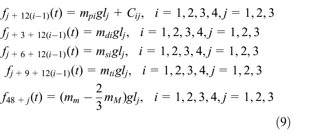
In the equation (7)∼(9), the terms
It is to be noted that depending on the different uneven ground conditions and the accuracy of control, the rotorcraft may land with one leg, or two legs, or three legs, four legs. There are three cases for each leg. One case is that the leg does not contact with the ground; one case is that the leg contacts with the ground and does not have the sliding velocity, we have

The maximum value of the friction coefficient
The dynamic analysis of the rotorcraft with robotic landing gear with uncertain-but-bounded parameters in the landing process on the uneven ground
The stiffness matrix

Obviously, the structural displacement vector

In practical engineering, the parameters of the above model may be uncertain due to complexity of structures, the uneven ground conditions, the accuracy of control, and the inaccuracy in measurement, etc. For this reason, there are uncertainties in parameter vector
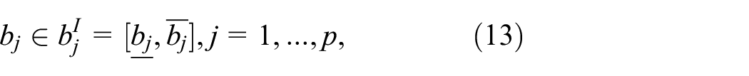
where

As the uncertainties in
Based on interval mathematics, the nominal value vector of the interval structural parameter vector

where

where

or the component form

where
where
where

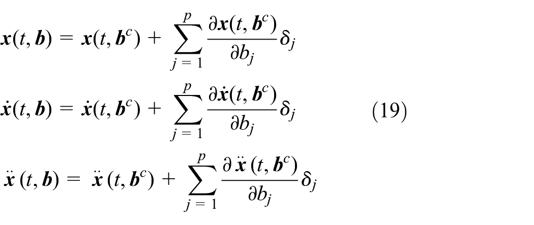
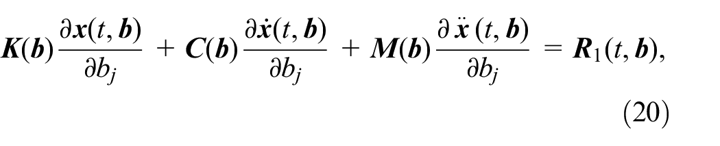
Substituting

Although there are the uncertainties in the structural parameters, it is of interest to find the effect of the uncertainties in the angles around the hip joints and the knee joints than the effect of the uncertainties in the structural parameters. The first-order partial derivative about the angles around the hip joints and the knee joints may be obtained by the expression as follows

Numerical examples and discussion
Example 1: The dynamic response of the rotorcraft with the robotic landing gear in the landing process
We assumed that
Comparison of the dynamic responses with the different legs
First we considered comparison of the dynamic responses of the rotorcraft with the different number of legs contacting with the ground in the landing process. Set the initial velocity of the rotorcraft as
Figures 3 to 5 show the comparisons of the dynamic displacement responses, the velocity responses, and the acceleration responses in the direction of the z-axis of the pad A with the different number of legs, where the pad A is the pad of the leg which is landing on the ground. It can be seen from the above figures that the dynamic displacement responses, the velocity responses, and the acceleration responses decrease as the number of legs are increased from one to four. The magnitudes of the responses for the case of the landing with one leg are very great then other cases.

Comparison of the dynamic displacement responses of the pad A with the different legs.

Comparison of the velocity responses of the pad A with the different legs.

Comparison of the acceleration responses of the pad A with the different legs.
Figures 6 and 7 show the comparisons of velocity responses, and the acceleration responses of the body with the different number of legs. Thus, in order to maintain the safety, the rotorcraft robotic landing gear would be controlled to adjust the condition of the ground to insure the landing with four legs on the ground at the same time.

Comparison of the velocity responses of the body with the different legs.

Comparison of the acceleration responses of the body with the different legs.
Comparison of the dynamic responses with the different initial velocities
Then we considered the comparison of the dynamic responses of the rotorcraft robotic landing gear with the different initial velocities in the landing process. Set the angle of the attack of the rotorcraft as
Figures 8 and 9 show the comparisons of the velocity responses and the acceleration responses in the direction of the z-axis of the pad A with the different initial velocities. It can be seen from the above figures that the velocity responses and the acceleration responses increase as the initial velocity is increased from 0.2 to 2 m/s. When the initial velocity is equal to 2 m/s, the maximum acceleration is greater than 16.1

Comparison of the velocity responses of the pad A with the different velocities.

Comparison of the acceleration responses of the pad A with the different velocities.
Comparison of the dynamic responses with the different angles of the sloped ground
Then we considered the dynamic responses of the rotorcraft with robotic landing gear with different angles of the sloped ground from
Comparison of the dynamic displacement responses of the pad A with the different angles of the sloped ground.

Comparison of the velocity responses of the pad A with the different angles of the sloped ground.

Comparison of the acceleration responses of the pad A with the different angles of the sloped ground.
It can be seen from the above figures that if the flight attitude of the rotorcraft can be controlled to adjust the landing on the uneven ground accurately, the dynamic displacement responses, the velocity responses, and the acceleration responses do not have the significant difference as the angles of the sloped ground is increased from
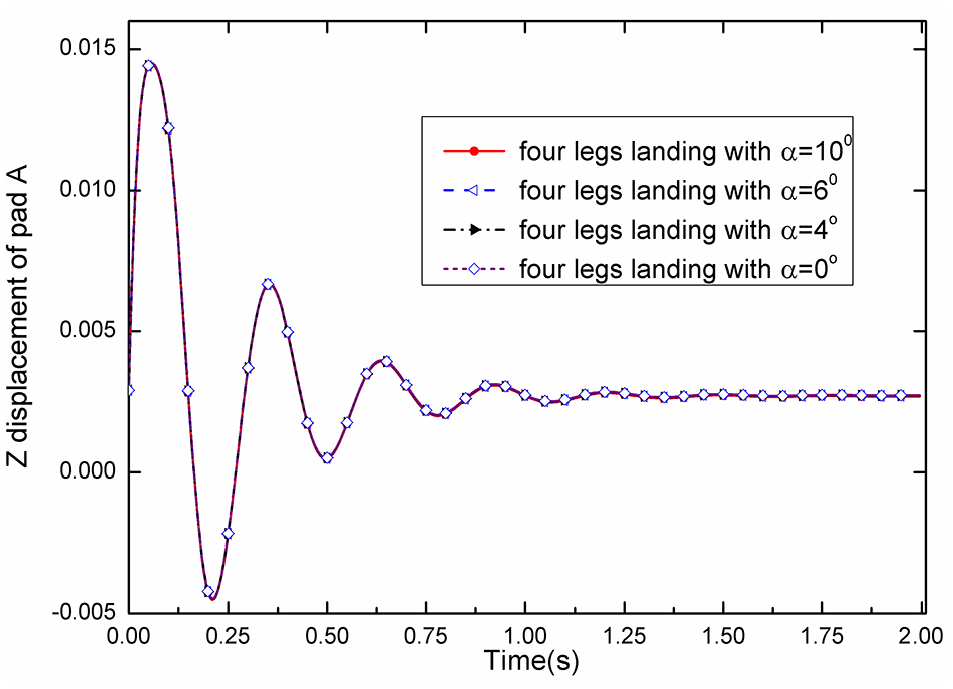
Comparison of the dynamic responses with different the angles of attack
Then we consider the dynamic responses of the rotorcraft with the robotic landing gear with different the angles of attack from

Comparison of the dynamic displacement responses of the pad A with different the angles of attack.

Comparison of the velocity responses of the pad A with different the angles of attack.
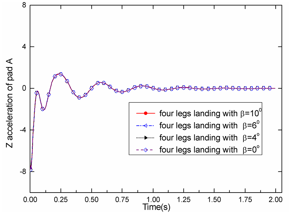
Comparison of the acceleration response of the pad A with different the angles of attack.
It can be seen from the above figures that the dynamic displacement response, the velocity responses, and the acceleration responses does not have the significant difference as the angle of the attack of the rotorcraft is increased from
Figure 16 shows that when the angle of the attack of the rotorcraft is less than

Comparison of the dynamic displacement response of the pad A with different the angles of attack.
Example 2: The dynamic response of the rotorcraft robotic landing gear with uncertain-but-bounded parameters in the landing process
Example 2 is similar to example 1, except that uncertain-but-bounded parameters is considered in this example. When the angle of the sloped ground is
Figures 17 to 19 show the comparisons of the bounds of the dynamic displacement responses, the velocity responses, and the acceleration responses in the direction of the z-axis of the pad A with the different uncertain factors. It can be seen from the above figures that the bounds of the dynamic displacement response, the velocity responses with
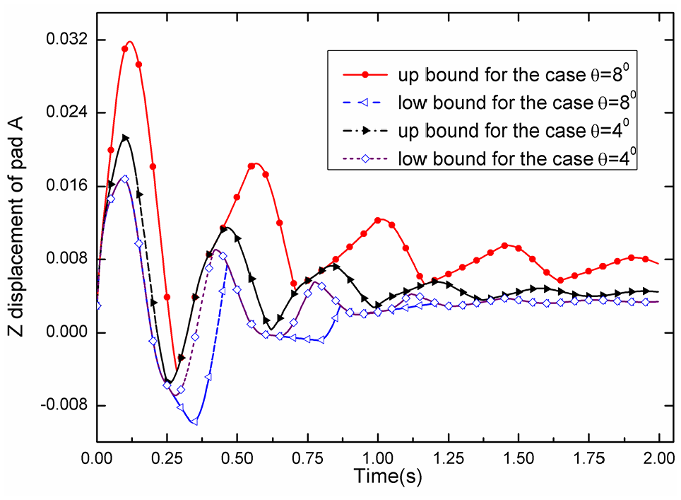
Comparison of the bounds of the dynamic displacement responses of the pad A with the different uncertain factor.

Comparison of the bounds of the velocity responses of the pad A with the different uncertain factor.
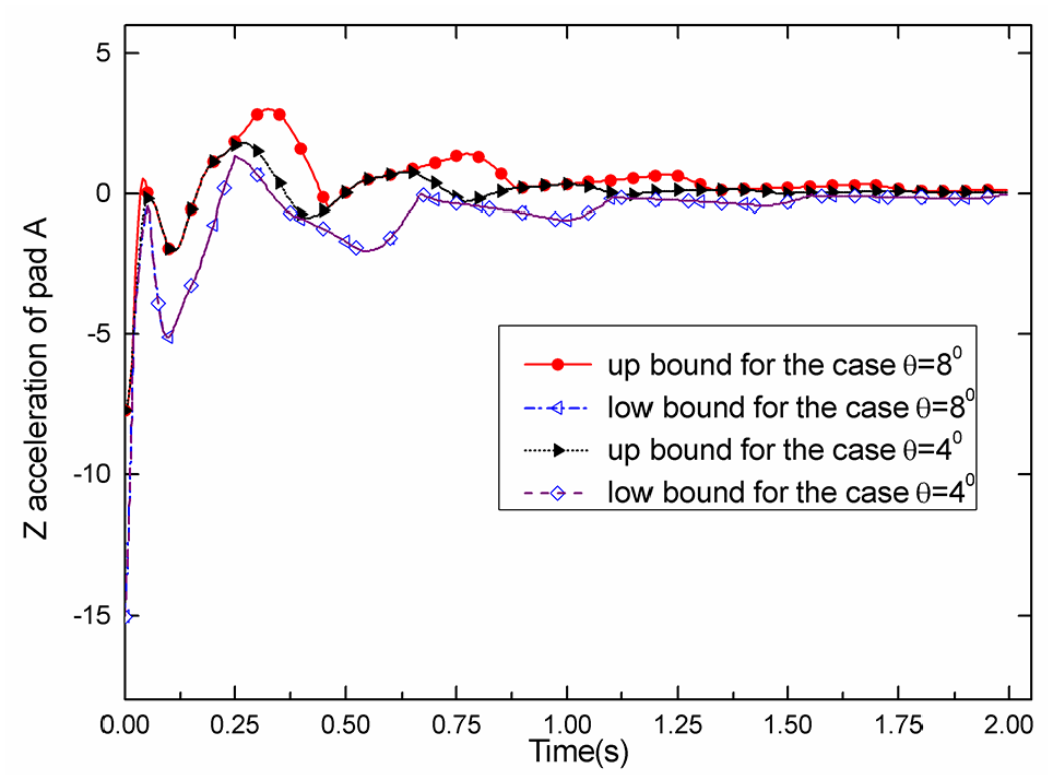
Comparison of the bounds of the acceleration responses of the pad A with the different uncertain factor.
Figures 20 and 21 show the comparisons of the bounds of the dynamic displacement responses and the acceleration responses of the pad A corresponding to uncertain factor

The bounds of the dynamic displacement response of the pad A versus the different uncertain factor.

The bounds of the acceleration response of the pad A versus the different uncertain factor.
These numerical results reveal that the large deviations of the angles around the hip joints and the knee joints would lead to drastic increases of the dynamic displacement response and the acceleration response of the pad, which may resulted in an overload of the rotorcraft.
Conclusions
In order to avoid the hard landing on the uneven ground which is resulted in serious fuselage damage, structural failure, or cargo damage, the robotic landing gears of the rotorcraft are designed. Thus the landing attitude can be changed by controlling the servomotors to change the angles of the thigh and the supporting leg of the robotic landing gears to adjust the landing condition of the uneven ground. Depending on the different uneven ground conditions and the accuracy of control, the rotorcraft may land with different number of legs and different landing conditions. In this work, based on the Lagrangian formulation, the dynamic model of the rotorcraft with different number of legs contacting with the ground in the landing process was derived, where the angle of the sloped ground and the angle of the attack of the rotorcraft were considered. Then, for estimation of the effect of the uncertainties on the response, an approach was presented to determine the lower bound and the upper bound of the dynamic response of the rotorcraft with uncertainties parameters. The results of numerical examples indicate that: (1) Under the same initial condition, the dynamic displacement responses, the velocity responses, and the acceleration responses decrease as the number of legs are increased from one to four. The magnitudes of the responses for the case of the landing with one leg are very great then other cases. (2) In order to maintain the safety, the rotorcraft robotic landing gear would be controlled to adjust the condition of the ground to insure the landing with four legs on the ground at the same time. (3) To maintain or improve the safety, the initial velocities are restricted to be less than certain value; (4) If the rotorcraft robotic landing gear is controlled to adjust the condition of the ground, the dynamic displacement response, the velocity responses, and the acceleration responses does not have the significant difference with different angles of the sloped ground and different angles of attack. (5) The large deviations of the angles around the hip joints and the knee joints would lead to drastic increases of the dynamic displacement response and the acceleration response of the pad, which may resulted in an overload of the rotorcraft.
Footnotes
Handling Editor: Chenhui Liang
Declaration of conflicting interests
The author(s) declared no potential conflicts of interest with respect to the research, authorship, and/or publication of this article.
Funding
The author(s) disclosed receipt of the following financial support for the research, authorship, and/or publication of this article: This study was supported by The National Natural Science Foundation of China (Nos. 91848203 and 91948303), Science Fund for Creative Research Groups of the National Natural Science Foundation of China (No. 61821005), theState Key Laboratory of Robotics (2020-Z02).