
Abstract
Considering the complex vibration phenomenon of turbine runner blades under the flow excitation, the nonlinear coupling dynamic equation, which contains hydraulic parameters and blade structure parameters, is established by the finite element method, based on geometrical nonlinearity and fluid–structure interaction of runner blades. According to the dynamic equation, the dynamic response of turbine runner blades under the flow excitation is simulated and analyzed through an example and is compared with the experimental results. The research shows that the proposed equation can well reflect the relation between the dynamic performance of turbine runner blades and its hydraulic parameters, structural parameters, and material parameters. Therefore, the equation provides a necessary theoretical basis for further study on deep-seated problems such as the dynamic characteristics of runner blade and the mechanism of vibration fatigue of runner blade.
Introduction
As the primary part of the hydraulic turbine generator unit, the runner blade directly interacts with the water flow with energy, which is the source of the flow excitation of the unit. The vibration problems constantly exist in the runner blade in the actual operation.1,2 And, the fatigue crack is easily generated on the blade under the long time vibration. While the crack propagates to a certain extent, the shape of the blade will be greatly changed, which causes hydraulic unbalance and a significant decline in the dynamic performance of the unit and even affects the safety of the unit. 3 For example, since the cracks appeared in the runner blades of the hydraulic turbine generator units of Yantan hydropower station, the operational efficiency of the generator units decreased greatly and strong vibration took place in the generator units. As a consequence, this hydropower station was forced to shut down to deal with the cracks, which greatly affected the economic benefits of the hydropower station. 4 Three Gorges hydroelectric power station is the largest hydropower station in China, and this world-renowned hydroelectric power station is also under the risk of blade cracking. 5 Therefore, in order to ensure the safe, reliable, and efficient operation of hydropower station, it is necessary to study deep-level questions such as the vibration characteristics of turbine blades, the law of dynamic changes of fatigue cracks, and the safety of the operation.
In the beginning, the vibration problems of the runner blade were researched mainly through the experiment.6,7 But, the cost of experiments was high, the amount of external disturbances factors was big, and some experiments were infeasible indeed. For the above reasons, the numerical method started to be used to study the vibration problems. With the development of numerical computing methods such as the finite elements and the boundary elements, some scholars began to try to analyze the vibration characteristics of blade structure in aqueous environment by the finite element method or the boundary element method. For instance, Dubas and Schuch 1 analyzed the dynamic characteristics of the runner blades in both air and water by the finite element method. Using the nonlinear elastic transient analysis, Fu et al. 2 studied the hydraulic vibration which was caused by the pressure fluctuation of flow on the runner blade. Zhang and colleagues8,9 took the Francis turbine as the research object and presented a calculation method to solve the strong coupling flow-induced vibration of elastic structure of a small deformation based on the stability finite element method. RA Saeed et al. 10 studied the property of flow excitation acting on the runner blade with different operating conditions by the flow analysis software CFD (computational fluid dynamics), and so on. However, the operating environment of runner blades is very severe. The runner blade not only undergoes the start-up and the shutdown but also often runs at off-design conditions. And the state of the water flow is usually so unstable for this reason that intense vibration in the runner blade is generated by complex flow excitation. Therefore, in order to do the further study on the dynamic performance of turbine runner blades and reveal the vibration mechanism of runner blades, it is necessary to establish a dynamic model that can fully reflect the intrinsic relation between the dynamic performance of turbine runner blades and hydraulic parameters, structural parameters, and material parameters.
In this article, the nonlinear fluid–structure coupling dynamic equations of Francis turbine runner blades are formulated and the intrinsic relation between the dynamic response of runner blades and hydraulic parameters, structural parameters, and material parameters of blades are revealed by the finite element displacement method. These studies provide a theoretical basis for a further study on the dynamic characteristics of turbine runner blades.
Finite element model of runner blades
As shown in Figure 1, the shape of turbine runner blades is the surface with a finite length. For the simplicity and generality of the model, the surface with a finite length can be assumed as a combination of numerous flat shell elements, so the runner blades are replaced by the rectangular flat shell elements for finite element simulation, during the process of establishing the finite element model of the rectangular flat shell element. Meanwhile, in order to decrease the difficulty of solving equations, the impact of elastic rotation angles is also neglected, as shown in Figure 2.

Diagram of structure of runner blade.
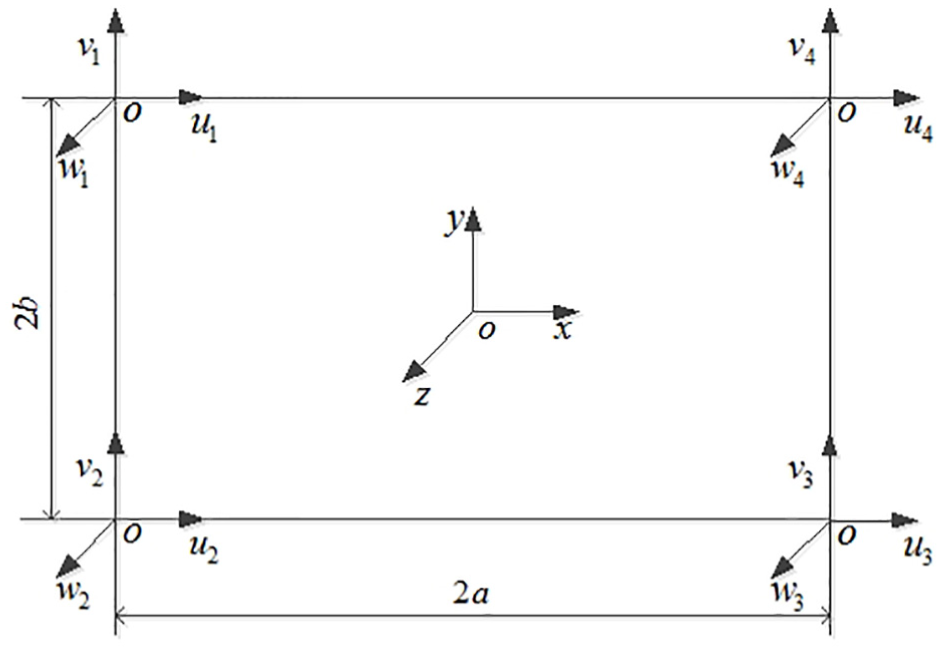
Finite element model of rectangular flat shell element.
Displacement components
In the finite element model of rectangular flat shell element shown in Figure 2, the coordinate system o-xyz is the local coordinate system of elements; a is the width of rectangular flat shell element, b is the length of rectangular flat shell element;

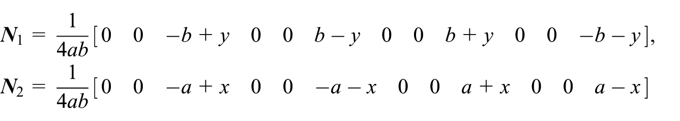
According to the finite element method, the mode of neutral plane displacements of the rectangular flat shell element can be written as follows

In above equations,

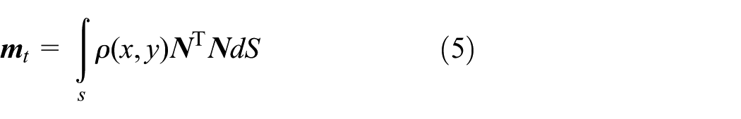
Kinetic energy of elements
According to the finite element method, the kinetic energy of rectangular flat shell element can be represented as follows

where
Substituting equation (1) into equation (3), and rearranging, the formula is

where
In the above equation,

Potential energy of elements
In the case of considering the large geometric deformation of runner blades, the strain–displacement relation of the rectangular flat shell element is 11

Substituting equations (1) and (2) into equation (6), and rearranging, the following formula can be obtained

where

and
From the stress–strain relation, it is known that

where
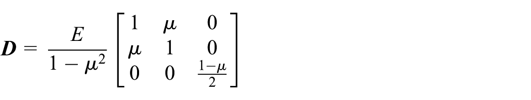
where
Then, elastic potential energy of the rectangular flat shell element can be written as follows
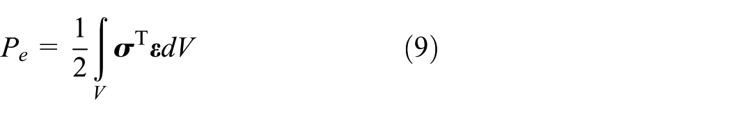
Substituting equations (7) and (8) into equation (9), respectively, and rearranging, the equation can be written as follows

where
Assuming that the fluid between two adjacent blades is steady and the water flow is a small-disturbance flow that is incompressible and non-viscous, the pressure energy of flow of the runner blade on the surface of the rectangular flat shell element can be expressed as follows 12

where
For non-viscous and incompressible fluid with the perturbation, based on the theory of hydromechanics, the vector of hydrodynamic pressure of the node

where
Substituting equation (12) into equation (11), and rearranging, the following formula of fluid pressure energy of the element,

The total potential energy of rectangular flat shell element of runner blade is made up of the elastic potential energy of the element

Substituting equations (10) and (13) into equation (14), and rearranging, the above equation (14) can be written as follows

Differential equations of motions of elements
Based on the Lagrange equation, differential equations of motion of rectangular flat shell element of runner blades can be obtained

where
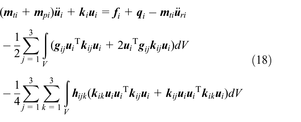
Substituting the formula of kinetic energy equation (4) and the formula of potential energy equation (15) into equation (11) and rearranging, taking no account of the effect of the damping, the differential equations of motions of the rectangular flat shell element of runner blades can be represented as follows

where
Dynamic equations of the runner blade
If the runner blade is divided into rectangular flat shell elements, then according to equation (17), the dynamic equation of the
where
The setup is that

where

As a result, the relation between the generalized coordinate vector

All differential equations of the motion of elements are added together, and the effect of damping is estimated approximately by the theory of viscous damping. Consequently, a damping term is introduced into the equation. Then, the dynamic equation of the runner blade with the influence of damping is obtained as follows 13

where

It is worth noting that the interaction forces
According to the derivation process of equation (21), the mass matrix
Simulation and analysis of dynamic response
Simulation object
Taking a 302MW Francis turbine whose type is HL286-LJ-800 of a hydropower plant in Guangxi as the research object,
14
the parameters of the runner are as follows: the maximum diameter of the runner is
In the literature, 14 the dynamic stress on the runner blade has been measured. The layout mode of measuring points and strain gauges is shown in Figure 3, and the lead of the test system is shown in Figure 4. Strain signals are collected by the telemeter, recorded by TEAC310C tape recorder, and handled by the data acquisition and analysis system HP38528. Figure 5 is the experimental time–domain dynamic response characteristics curve of measuring point 2 with the operating condition 120 MW. 14 According to Figure 5, the maximum dynamic stress, the minimum dynamic stress, and the root mean square values of the dynamic stress of this measuring point are 26.82, −19.05, and 7.51 MPa, respectively.

Distribution of the measuring point of dynamic stress on the blade.

Schematic representation of lead of dynamic stress test.

Experimental time–domain dynamic response characteristics curve of measuring point 2.
Simulation and analysis
In order to compare with the experimental results in the previous work,
14
the dynamic characteristics of turbine runner blades are analyzed when the operating condition is 120 MW. Because the operating condition 120 MW is the low-load condition of the Francis hydraulic turbine generator unit, the value of pressure fluctuation in the draft tube is large in this condition. Thus, the main consideration is the pressure fluctuation caused by the asymmetry of the force of the flow when the water flows into or out of the runner and the low-frequency vortex in the draft tube. According to the work by Yang,
15
when the operating condition is 120 MW, the excitation amplitude of the pressure fluctuation is
For the simplicity and the generality, the turbine runner blade is divided into six rectangular elements, 12 nodes, and 27 displacements, so there are 27 degrees of freedom for each turbine runner blade. The element number is presented by ①, ②, ③, ④, ⑤, ⑥, and the node number is presented by 1, 2, 3, 4, 5, 6, 7, 8, 9, 10, 11, 12, where


Schematic representation of the dynamical model of the turbine runner.
According to the dynamic model of the runner shown in equation (22), the intrinsic properties of turbine runner blades are solved through programming by MATLAB. The first five-order natural frequencies of turbine runner blades are shown in Table 1.
First five-order natural frequencies of runner.
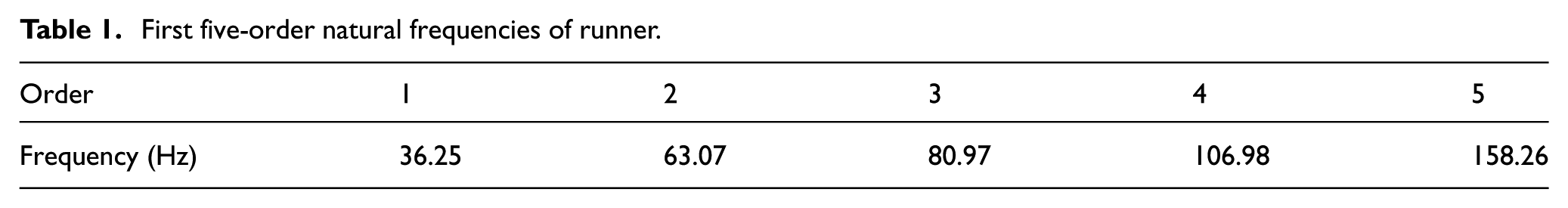
The first approximate solution of the dynamic response of the runner blades of the turbine is obtained using the multi-scale method, based on the dynamic equation of the runner blade shown in equation (21). The dynamic stress along the x and y directions in the local coordinate system in the X and Y directions along the local coordinate system at any location on the blade can be calculated according to equations (7), (8), and (20).
The dynamic stress perpendicular to the outlet edge is mainly simulated and calculated because the cracks on the outlet edge of runner blades are generally perpendicular to the outlet edge. 14 Figures 7–9 show the simulation time–domain dynamic response characteristics curves of nodes 6, 9, and 12, respectively. Node 6, 9, and 12 are all the nodes on the outlet edge of the blade, and node 6 is the same as the measuring point shown in Figure 3. From to the simulation time–domain dynamic response characteristics curves of nodes 6, 9, and 12, it can be seen that the dynamic stress of node 6 near the upper canopy and node 12 near the lower band is larger than the dynamic stress of the node 6 at the middle of the blade’s outlet edge. According to the theory of fracture mechanics, the node 6 near the upper canopy and the node 12 near the lower band are more prone to generating fatigue cracks than the node 9 at the middle position. In the work by Yang et al., 13 the locations of 24 cracks that produced on the runner blades of the turbine runner blades were counted. The statistical results were that 12 cracks appeared near the canopy of the blade, 9 cracks appeared near the lower band of the blade, and the other 3 cracks were on other parts. In other words, the fatigue cracks of the runner blades mainly appear near the upper canopy and the lower band. It is obvious that results of the simulation analysis are basically consistent with the experimental results.
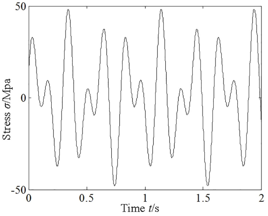
Simulation time–domain dynamic response characteristics curve of node 6.

Simulation time–domain dynamic response characteristics curve of node 9.

Simulation time–domain dynamic response characteristics curve of node 12.
In the meantime, according to the simulation time–domain dynamic response characteristics curve of node 9 shown in Figure 8, the maximum dynamic stress, the minimum dynamic stress, and the root mean square values of the dynamic stress of node 9 are 22.88, −16.89, and 11.02 MPa, respectively, which are basically consistent with the experimental results shown in Figure 5.
Conclusion
Considering the flow excitation, the dynamic equations of turbine blades are established by the finite element displacement method. The proposed equations not only contain the fluid–solid coupling term but also contain the nonlinear term due to the large geometric deformation of the blades. The dynamic equations are the nonlinear fluid–structure coupling dynamic equations.
When the runner blades are forced by the flow excitation, the dynamic responses near the upper canopy and the lower band of the turbine runner are larger than that at the middle position. As a result, the fatigue cracks are more likely to appear in the upper canopy and the lower band of the runner blade.
The established coupling dynamic model of runner blade not only reflects the intrinsic relations between the dynamic responses and hydraulic parameters, structural parameters, and material parameters but also provides the necessary theoretical basis to investigate into the deep-seated problems about the coupling mechanism of vibration and fatigue of runner blade.
Footnotes
Acknowledgements
The authors are grateful to reviewers for their valuable remarks.
Handling editor: Shun-Peng Zhu
Declaration of conflicting interests
The author(s) declared no potential conflicts of interest with respect to the research, authorship, and/or publication of this article.
Funding
The author(s) disclosed receipt of the following financial support for the research, authorship, and/or publication of this article: The research was supported by National Natural Science Foundation of China under grant nos 51465001 and 51065002. The supports are gratefully acknowledged.