
Abstract
A finite element model of wellbore stability was proposed for a horizontal well, and drill-string friction and lateral collision in the process of rotary motion were taken into account. An unconfined compression test was used for model validation, the normalized yielded zone area (NYZA) was employed to analyze wellbore stability, and the influence of a lateral collision on wellbore stability was simulated. The results indicated that the stress-strain curve of numerical simulation consists with unconfined compression test, and the maximum relative error is <2.2%. The evolution of NYZA can be divided into three typical stages: stage I (static balance), stage II (dynamic growth), and stage III (dynamic balance). Both normal and shear stresses reach to the peak value in stage II, while they always fluctuate in a relatively small range in stage III, so that the wellbore stability mainly affected by the first collision of drill-string. Both lateral acceleration and friction effects have significant impact on wellbore stability. The initial collision position and the size of drilling tool have a certain influence on wellbore stability, while the revolving speed of drill-string almost has no impact. The present paper has guiding significance for wellbore collapse prevention and drilling parameter optimization.
Keywords
Introduction
With the depletion of global conventional oil and gas resources, and the development of unconventional oil and gas resources has gradually attracted attention.1,2 Based on the assessments of IEA (International Energy Agency), the output of unconventional natural gas after 2035 will exceed 1.6 trillion cubic meters. 3 Long-displacement horizontal well and hydraulic fracturing are the key technologies for the exploitation of unconventional oil and gas resources, due to the horizontal well and hydraulic fracturing can increase the drainage area, increase the penetration of producing formation, improve the productivity by hydraulic fracturing, and increase the efficiency of enhanced oil recovery (EOR).4–6 However, in the process of horizontal drilling for unconventional oil and gas reservoir, the wellbore instability is one of the most common and serious downhole complication and accident during drilling operation, which usually cause to drill pipe sticking and drill pipe burying even lead to abandon of wellbore, which also seriously affects drilling safety, efficiency, and cycle.7,8
In general, the reasons of wellbore instability can be divided into two major categories9–13: (1) objective factors and (2) subjective factors. Among them, the objective factors mainly depend on the lithology, 13 rock mechanical properties, 14 in-situ stress, 15 and geological conditions. 16 The objective factors can’t be changed and only can be accurately recognized and utilized during drilling operation.17,18 The subjective factors mainly depend on the disturbance induced by drilling operations, including wellbore trajectory, wellbore pressure, wellbore temperature, drilling fluid chemistry, and drill-string collision.19–24 Currently, many scholars focused on the determination of reasonable wellbore pressure or drilling fluid density, wellbore trajectory optimization, and chemical anti-collapse measure of the drilling fluid.23–26 However, regarding the wellbore instability caused by drill-string collision has not been paying enough attention.
In fact, drill-string hits the wall of wellbore can be called as the drill-string collision, which mainly caused by drill-string vibration. According to the direction of vibration, drill-string vibration can be divided into three categories27–31: (1) lateral vibration, (2) torsional vibration, and (3) longitudinal vibration. The lateral vibration is that the direction of drill-string vibration is perpendicular to the drill-string’s central axis, the torsional vibration mainly refers to intermittent movement of drill-string around the central axis with unstable rotation, and the longitudinal vibration is that the direction of drill-string vibration is along the central axis of drill-string.27,28 Several scholars investigated the characteristics of the downhole drill-string vibration by using downhole instrument or numerical simulation.32–34 Field et al. 35 analyzed the actual data of downhole drill-string vibration, they pointed out that when the wellbore is relatively smooth, the lateral acceleration of drill-string is generally 20–30g, while when the wellbore is rough, the lateral acceleration can reach to 70g or even more than 80g. Dykstra et al. 36 compared the results of field testing and numerical simulation, they found that the lateral acceleration is usually >20g, even up to 200g, and the vibration source is mainly the interaction between the drill bit and bottom rock, and between drill-string and wellbore. Skaugen and Kyllingstad 37 analyzed the actual downhole loading and acceleration data, they found that longitudinal vibration and torsional vibration of drill-string have a certain degree of randomness, and the collision and friction between drill-string and wellbore rock is one of the main reasons for this phenomenon. Heisig and Neubert 38 also analyzed the actual downhole vibration data and found that the phenomenon of drilling jumping and bit bouncing will be happened in the event of severe vibration. Kamgue Lenwoue et al. 39 developed a 3D finite element model using poro-elastoplastic theory to investigate the effect of drill-string vibration cyclic load on the propagation of natural fractures on the wall of wellbore, the results indicated that there is a clear relationship between fracture diameter, leakage rate and drill-string vibration cyclic load. Rafezi and Hassani 40 developed a novel qualitative method based on extensive field studies to investigate the relations between drilling vibration as well as electric motor current signals and bit wear, introduced bit failure vibration frequencies, regardless of the geological conditions. The above studies indicated that excessive lateral vibration of drill-string is harmful to drilling engineering. The lateral vibration is easy to cause drill-string whirling, which is the phenomenon of drill-string rotating on its own central axis and revolving around the wellbore axis,27,28,32 and the drill-string whirling can be classified into backward whirling and forward whirling. In general, drill-string whirling could aggravate the collision between drill-string and wellbore, 9 and cause the loosing or failure of drilling tool thread. 11 On the whole, excessive lateral vibration or whirling may cause to wellbore collapse, drill pipe sticking, and drill pipe burying, even lead to abandon of wellbore, which also seriously affects drilling safety, efficiency, and cycle.7–13,41
In order to study the impact of drill-string vibration on the wellbore stability, Pla’cido et al. 42 measured the hook load, rotation speed, torque, sand pipe pressure, and downhole acceleration parameters of three wells in the Amazon area, they analyzed the drill-string vibration monitoring results and found that the wellbore stability of two wells with almost the same lithology showed obvious differences after different levels of the drill-string vibration, which shows that the drill-string collision has a significant effect on wellbore stability. Santos et al.43,44 analyzed the energy changes during drilling based on the principle of energy conservation, they found that drill-string collisions can cause a significant increase in the internal energy of the rock and affect the wellbore stability to go a step further, moreover, the analysis results of two wells in Brazil also found that drill-string collisions were more likely to cause wellbore instability in hard rock formations. Khaled and Shokir 45 developed a prediction model of critical vibration parameters for the wellbore collapse caused by drill-string vibration, combined with the analysis of the field case and found the wellbore instability caused by drill-string vibration is more likely happened in a small wellbore with a diameter of <153.4 mm, the rotation speed is the main factor aggravates the collision between drill-string and wellbore. Khaled 46 further studied the form of wellbore instability caused by drill-string vibration, and three kinds of typical failures were found: (1) compression failure, (2) shear failure, and (3) fatigue failure. AlBahrani et al. 47 proposed an analysis method of wellbore stability based on time-delay well logging and surveyed the dates in 21 well intervals of 17 straight wells, the results displayed that one of the main reasons for wellbore stability deteriorates with time is the times and the distance of the drill-string vibration are greater, so that the lateral force exerted on the wellbore is too high to cause the rock failure in yield zone. Zhu et al.48,49 established a finite element model (FEM) of wellbore collided by a drill-string under air or gas drilling conditions, they conducted a series of physical simulation experiments for the wellbore rock collided by iron ball, and they analyzed the relationship between rock fragmentation volume and drill-string collision.
In the above researches, the statistical analysis results based on the field measured data42,45–47 can only be applied to offset wells, similar geological structures, or similar blocks, the knowledge and analysis results based on the energy conservation method43,44 gives barely qualitative understanding, the numerical simulation methods48,49 merely investigated the impact of drill-string collision on the stability of a vertical wellbore under air or gas drilling. There are no such literatures about the wellbore stability of horizontal wells with the influence of drill-string collision, the effect of drill-string friction and collision had not been investigated yet. Therefore, based on the theory of rock mechanics and drill-string dynamics, the present paper established an elastoplastic damage model for wellbore stability analysis, and drill-string friction and collision in the process of rotary motion were taken into account. The elastoplastic damage model was solved by finite element method (FEM), and an unconfined compression test was employed to verify this model. The influence of the drill-string collision on wellbore stability of a horizontal well was simulated, and the parametric studies were conducted to reveal the influence of drill-string friction and collision on wellbore stability. The analysis results can provide guidance for the wellbore collapse prevention, drilling parameter optimization, drilling safety and efficiency.
Constitutive model and yield criterion of rock
The most common used rock constitutive relations are linear elastic model, poro-elastic model, thermo-poro-elastic model, chemo-poro-elastic model, chemo-thermo-poro-elastic model, elastic- plastic model, poro-elastic-plastic model, thermo-poro-elastic-plastic model, chemo-poro-elastic-plastic model, and chemo-thermo-poro-elastic-plastic model.7–12,48–52 In the present paper, the elastic-plastic relationship with damage evolution is employed, as shown in Figure 1. The material properties of rock initially exhibit linear elasticity, and then exhibit plastic yield and strain hardening. After the yield strength is exceeded, damage occurs and begins to develop, and the bearing capacity of the rock decreases until it disappears completely. Where σy0 is the critical yield stress and

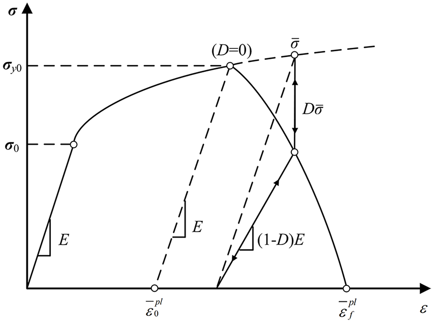
Stress-strain relationship of elastoplastic damage.
Where D is the damage factor; E is the elastic modulus of rock without damage; E′ is the equivalent elastic modulus of rock with damage; σ is the real stress value on the stress-strain curve;
Many rock yield criteria are used extensively, such as Mohr-Coulomb criterion, Drucker-Prager criterion, Mogi-Coulomb criterion, and Hoek-Brown criterion.48,49,53–57 Among them, the Drucker-Prager criterion contains the influence of the maximum and minimum principal stresses, also considers the influence of the intermediate principal stress. Therefore, the linear Drucker-Prager criterion was employed48,49,55,57:

where,
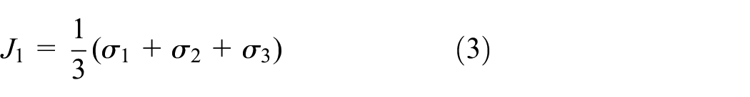

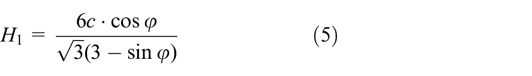

Where J1 is the first stress invariant; J2 is the second stress invariant; σ1 is the maximum principal stress; σ2 is the intermediate principal stress; σ3 is the minimum principal stress; H1 and H2 are the rock material constants; c is the cohesive strength of the rock; φ is the internal friction angle of the rock.
FEM modeling
Problem description and assumptions
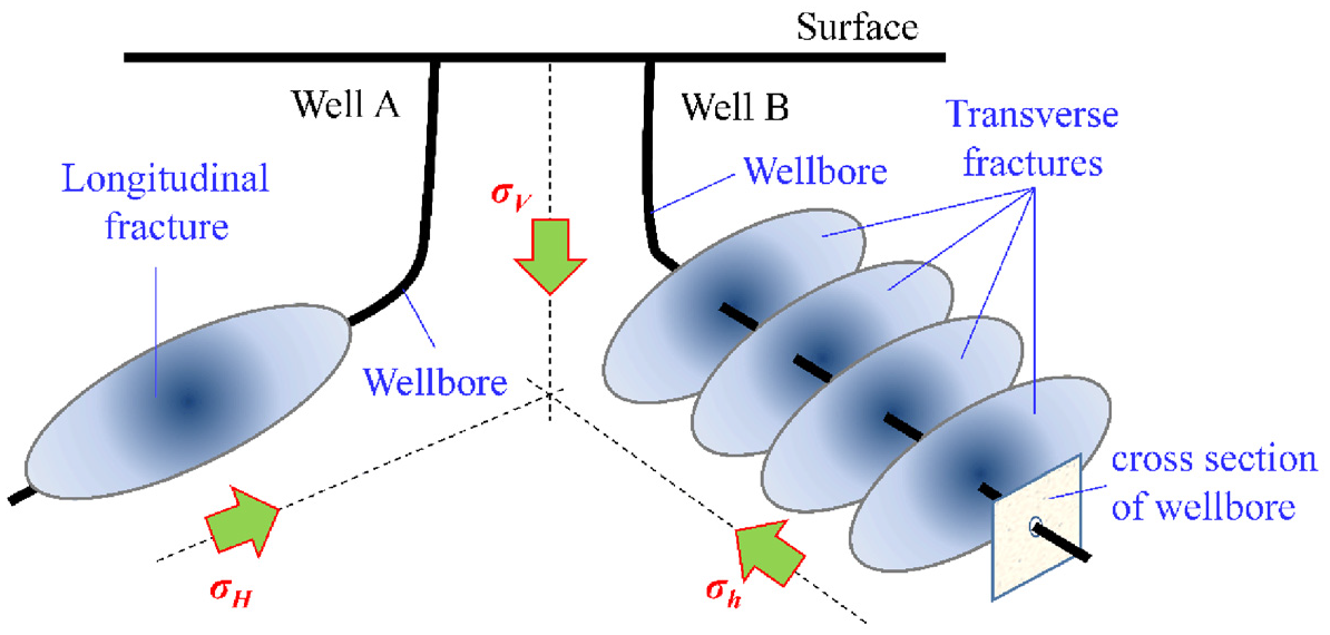
Considering a normal faulting stress regime, that is, σV > σH > σh, as shown in Figure 2, if the horizontal well is drilled in the direction of maximum horizontal stress, the longitudinal hydraulic fractures are likely to be initiated along or parallel to the wellbore axis, and if the horizontal well is drilled in the direction of minimum horizontal stress, then the transverse hydraulic fractures are initiated perpendicular to the wellbore axis. 58 Therefore, in order to meet the requirements of hydraulic fracturing and enhanced recovery, the direction of horizontal well is usually drilled along the direction of minimum horizontal stress. Thus, we take the horizontal well along the direction of minimum horizontal stress as the object of study, and the 2D physical model of a horizontal wellbore can be simplified, as shown in Figure 3. The formation rock around the horizontal wellbore subjects by far field stress of vertical stress (σV) and maximum horizontal stress (σH), and the wellbore pressure (pw) directly acts on the wall of wellbore. The wellbore and drill string has a radius of R and r respectively, the drill-string is located at the center of wellbore with an initial revolving speed (ω) and lateral velocity (Vr), and the drill-string will free move in the wellbore and interact with wellbore. There is a friction effect between drill-string and wellbore, and the friction meets the Coulomb’s friction law. In order to simplify the numerical model, the following assumptions are made:
Rock is homogeneous isotropic material and satisfies the assumption of small deformation;
Rock deformation is regarded as a plane strain problem;
The initial position of the drill string coincides with the wellbore axis;
The lateral acceleration (a) is equivalent to an initial lateral velocity (Vr);
The friction between drill-string and wellbore meets the Coulomb’s friction law;
The influence of wellbore pressure fluctuation, temperature and seepage effects are ignored.
Effect of wellbore direction on hydraulic fractures (Modified from Bahrami et al. 58 ).

2D physical model of wellbore stability.
FEM modeling and solution
According to the 2D physical model of wellbore stability, a FEM model was proposed, which has a wellbore radius of 108 mm and a drill-string diameter of 63.5 mm, as shown in Figure 4. According to the Saint-Venant principle, the model size is 600 ×600 mm to avoid any boundary effects. The mesh of the formation rock in the FEM model was divided by CPE4R (four nodes bilinear plane strain element) in ABAQUS software, and the sectional elements are denser in the area where close to the hole to improve the calculating accuracy, and there is a total element of 15,695. The mesh of drill pipe was also divided by CPE4R, and there is a total element of 3601. After the geometry and mesh model was proposed, the material properties were set in ABAQUS software, and the material properties were listed in Table 1.

FEM mesh of wellbore stability analysis.
Basic parameters of numerical simulation.

In order to solve this model, the boundary conditions should be set, and it is related to solution process. In the present paper, there are two major numerical simulation steps:
Step 1: Static balance simulation. Firstly, the displacement of the formation rock on the X and Y axis of symmetry was constrained by Y and X. Secondly, due to this model cannot involve the pore pressure, the effective vertical stress
Step 2: Dynamic implicit analysis. On the basis of step 1, the drill-string and wellbore are assembled on the central point RP, the drill-string was set as a rigid body, and the lateral acceleration, revolving speed, and Coulomb’s friction were applied to the drill-string. Among them, the revolving speed was directly applied to the drill-string. The lateral acceleration was applied according to the assumption of lateral acceleration is equivalent to an initial lateral velocity, and the lateral acceleration could be determined45,48,
Model validation
In order to verify the elastoplastic damage model, a laboratory unconfined compression testing of a Longmaxi shale rock was employed. According to the X-ray diffraction (XRD) testing result, the shale rock specimen is featured by rich in clay mineral and quartz, followed by feldspar, pyrite and dolomite, with the relative content of 42.61%, 28.26%, 12.49%, 6.95%, 5.51%, and 4.18%, respectively. 59 The shale specimen was cored as a standard cylinder with a diameter of 25 mm and height of 50 mm, the stress-strain curve of unconfined compression test was tested using a type of RTR-1000 rock triaxial testing system, and the stress-strain curve was then compared with the FEM simulation. For FEM simulation of unconfined compression test, the material properties were set as Table 1, the lower end face is fixed and the upper end face was loaded with displacement loading, eventually the yield failure was happening, and the results were shown in Figure 5. The results indicated that the stress-strain curve of numerical simulation consists with unconfined compression test, the yield strengths vary slightly, and the maximum relative error is less than 2.2%, and the stress concentration is almost along a dip angle of 45° of the unconfined compression specimen. Thus, the elastoplastic damage model was verified.

Comparison of numerical and laboratory unconfined compression testing results.
Numerical simulation results
In order to determine the degree of wellbore instability, the normalized yielded zone area (NYZA) was employed, as shown in Figure 6, the NYZA refers to the ratio of the plastic yield zone area (A1) in the vicinity of wellbore to the original cross-sectional zone area (A2) of the wellbore.60–62 Hawkes and McLellan60–62 believe that when the NYZA is more than a value depends on the different situations, the risk of the wellbore stability is increased.

According to the basic parameters listed in Table 1, the wellbore stability of a horizontal wellbore was simulated using the above-mentioned FEM model, the drill-string was set with a revolving speed of 60 rpm, a friction coefficient of 0.1, and a lateral collision acceleration of 70g with the direction pointed to the right, that is, the direction of maximum horizontal stress. The results were shown in Figures 7 to 9, where Figure 7 showed the evolution of NYZA, normal stress, and shear stress in the process of drill-string collision, Figure 8 showed the equivalent plastic strain of the surrounding rock around the wellbore at different stages, and Figure 9 showed the path of the drill-string center in the process of drill-string collision. As shown in Figures 7 and 8, the evolution process of NYZA around the wellbore caused by drill-string collision can be divided into three stages: (1) Stage I: Static balance, (2) Stage II: dynamic growth, and (3) Stage III: dynamic balance.
Static balance (Stage I): the surrounding rock around the wellbore subjected by far field in-situ stresses (σV and σH) and wellbore pressure (pw), and the drill-string keep static, so that the NYZA just depends on the static loading, shown in Figures 7, 8(a) and (b), the NYZA is always 0.0938, and the risk of wellbore instability increased when NYZA exceeds 0.0938. In this stage, both normal and shear stresses keep constants, and the normal stress controlled by effective wellbore pressure, while the shear stress keeps zero.
Dynamic growth (Stage II): the drill-string collides with the wellbore for the first time, as shown in Figures 7, 8(c) and (d), the normal stress and shear stress reached to the peak value when the drill-string collides with the wellbore for the first time, and NYZA dramatically increased from 0.0938 to 0.3155. In this stage, both normal and shear stresses reach to the peak value, and the wellbore stability is therefore affected by drill-string lateral collision.
Dynamic balance (Stage III): the drill-string keeps several collisions at random, then the drill-string makes a clockwise circular motion close to the wall of wellbore, as shown in Figure 9. As shown in Figures 7 and 8(e) to (i), the normal stress and the shear stress keep the fluctuation in a small range, and the NYZA was no longer to increase. In this stage, both normal and shear stresses always fluctuate in a relatively small range, so that the drill-string lateral collision has no significant impact on wellbore stability.

Evolution of NYZA, normal stress, and shear stress in the process of drill-string collision.

Evolution of equivalent plastic strain of the surrounding rock around the wellbore: (a) Stage I @ point a, (b) Stage I @ point b, (c) Stage II @ point c, (d) Stage II @ point d, (e) Stage III @ point e, (f) Stage III @ point f, (g) Stage III @ point g, (h) Stage III @ point h, and (i) Stage III @ point i.

Path of the drill-string center in the process of drill-string collision: (a) Drill-string centrode in the wellbore, and (b) Drill-string centrode.
In addition, as shown in Figures 7 and 9, all of the normal stress, shear stress, NYZA, and drill-string centrode do not change significantly after the first collision of drill-string on the wall of wellbore. Therefore, after the first collision of drill-string on the wall of wellbore, there may be no significant impact on simulation results due to drill-string trends to be in revolution motion, and both normal and shear stresses always fluctuate in a relatively small range, as shown in Figures 7 and 9. In general, the first collision of drill-string on the wall of wellbore should be occurred in a period of 1.5 s. In other words, when the calculating period exceeds 1.5 s, there may be no significant impact on simulation results, and the numerical simulation period was set at 1.5 s to save simulation time and costs.
Parametric studies
Effect of friction coefficient
In order to investigate the effect of friction coefficient on wellbore stability, according to the basic parameters listed in Table 1, the wellbore stability of a horizontal wellbore was simulated using the above-mentioned FEM model, the drill-string was set with a revolving speed of 60 rpm and a lateral collision acceleration of 70g were equivalent to an initial lateral velocity of 2.50 m/s, and the direction of initial lateral velocity pointed to the right (the direction of maximum horizontal stress). In addition, the friction coefficient ranged from 0 to 0.5. The numerical simulation results were shown in Figures 10 to 12. Compared the results of considering friction (μ ≠ 0) and frictionless (μ = 0) conditions, the NYZA of considering the friction effect with μ = 0.1 is almost twice of frictionless condition. With the increase of friction coefficient from 0.1 to 0.5, the corresponding NYZA increases almost linearly, and its linear fitting equation is NYZA = 0.2μ + 0.2952 (R2 = 0.9948). In the process of drill-string lateral collision, both normal and shear stresses reach to the peak value in stage II, and both normal and shear stresses always fluctuate in a relatively small range in stage III, so that the wellbore stability is mainly affected by the first collision of drill-string on the wall of wellbore. With the increase of friction coefficient from 0 to 0.5, the peak value of normal stress increases firstly and then tends to be a constant, and it increases almost linearly when μ ≤ 0.3, while it tends to be a constant when μ > 0.3. With the increase of friction coefficient from 0 to 0.5, the peak value of shear stress decreases firstly and then increases, and it almost reaches the lowest when μ = 0.2–0.4. Therefore, after considering the friction effect, the NYZA is obviously greater than that frictionless condition, which confirmed that the friction effect between the drill-string and the wellbore has a significant influence on the wellbore stability, and the rougher the wall of wellbore, the rock on the wall of wellbore is more likely to be damaged by drill-string collisions.

NYZA under different friction coefficients.

Normal stress under different friction coefficients.
Shear stress under different friction coefficients.
Effect of lateral acceleration
In order to investigate the effect of lateral acceleration on wellbore stability, according to the basic parameters listed in Table 1, the wellbore stability of a horizontal wellbore was simulated using the above mentioned FEM model, the drill-string was set with a revolving speed of 60 rpm and a friction coefficient of 0.1, the lateral collision accelerations of 30–120g were equivalent to different initial lateral velocity of 1.63–3.27 m/s, and the direction of initial lateral velocity pointed to the right (the direction of maximum horizontal stress). The numerical simulation results were shown in Figures 13 to 15. With the increase of lateral vibration acceleration from 30 to 120g, the NYZA increases nonlinearly, and the fitting equation is NYZA = 2.0 ×10⁻⁵a2 + 0.0003a + 0.2286 (R2 = 0.9899). Similarly, in the process of drill-string lateral collision, both normal and shear stresses reach to the peak value in stage II, and both normal and shear stresses always fluctuate in a relatively small range in stage III, so that the wellbore stability is mainly affected by the first collision of drill-string on the wall of wellbore. With the increase of lateral acceleration from 30 to 120g, the peak value of normal stress increases nonlinearly, and the fitting equation is σnpk = −0.0001a3 + 0.0258a2−1.3599a + 84.438 (R2 = 0.9899), while the peak value of shear stress increases firstly and then decreases. Therefore, on the whole, the lateral vibration acceleration of the drill-string has also a great influence on the wellbore stability, the main reason is the peak normal stress exceeds the yield strength of wellbore rock, finally, the area of the wellbore damage zone become much larger, and the rock on the wall of wellbore is more likely to be unstable.
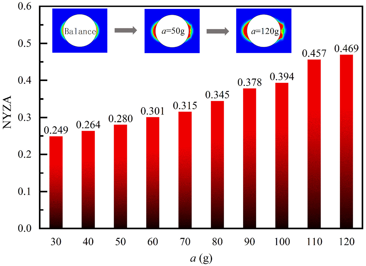
NYZA under different lateral vibration acceleration.

Normal stress under different lateral vibration acceleration.

Shear stress under different lateral vibration acceleration.
Effect of collision position
In order to investigate the effect of collision position on wellbore stability, according to the basic parameters listed in Table 1, the wellbore stability of a horizontal wellbore was simulated using the above mentioned FEM model, the drill-string was set with a revolving speed of 60 rpm and a friction coefficient of 0.1, the lateral collision accelerations of 30–120g were equivalent to different initial lateral velocity of 1.63–3.27 m/s, meanwhile the direction of initial lateral velocity (collision position) pointed to the wellbore low-side (the direction of vertical stress) and lateral-side (the direction of maximum horizontal stress). The numerical simulation results were shown in Figure 16. The results indicated that when the initial lateral velocity pointed to the wellbore lateral-side, its NYZA is obviously larger than that of the wellbore low-side. The fitting equation of NYZA under the collision position of wellbore low-side is NYZA = −6.0 × 10⁻⁶a2 + 0.0034a + 0.1047 (R2 = 0.9927), while the fitting equation of NYZA under the collision position of wellbore lateral-side is NYZA = 2.0 × 10⁻⁵a2 + 0.0003a + 0.2286 (R2 = 0.9899). This phenomenon indicated that drill-string collision on the wellbore lateral-side has a greater impact on the wellbore stability. When the formation is drilled to form a wellbore, the rock in the vicinity of wellbore from the direction of the minimum principal stress has already happened stress concentration, after sustaining a violent collision form the drill string, the area of the wellbore damage zone is further expanded and the risk of instability is therefore generated.

NYZA under the different collision position on the wellbore.
Effect of revolving speed
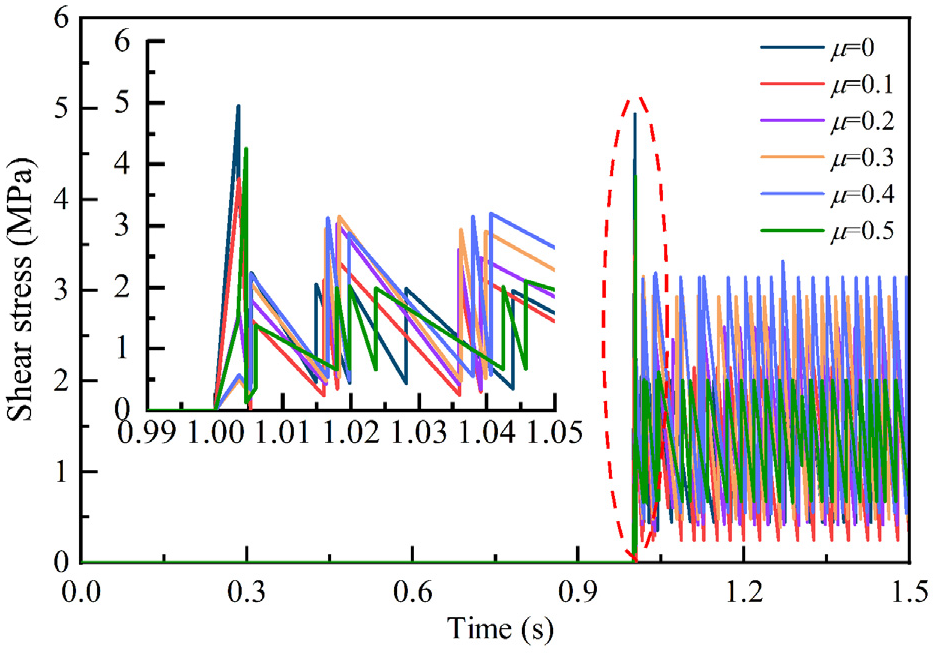
In order to investigate the effect of revolving speed on wellbore stability, according to the basic parameters listed in Table 1, the wellbore stability of a horizontal wellbore was simulated using the above mentioned FEM model, the drill-string was set with a friction coefficient of 0.1 and a lateral collision acceleration of 70g, and lateral collision acceleration of 70g were equivalent to an initial lateral velocity of 2.50 m/s, and the direction of initial lateral velocity pointed to the right (the direction of maximum horizontal stress). In addition, the revolving speed was ranged from 30 to 120 rpm. The numerical simulation results were shown in Figures 17 to 19. Similarly, in the process of drill-string lateral collision, both normal and shear stresses reach to the peak value in stage II, and both normal and shear stresses always fluctuate in a relatively small range in stage III, so that the wellbore stability is mainly affected by the first collision of drill-string on the wall of wellbore. With the increase of the revolving speed of drill-string, the NYZA, normal stress, and the shear stress almost has no significant change, both in the peak value and the range of subsequent fluctuations. The results indicated that there is no obvious relation between the drill-string’s revolving speed and the area of the wellbore damage zone.
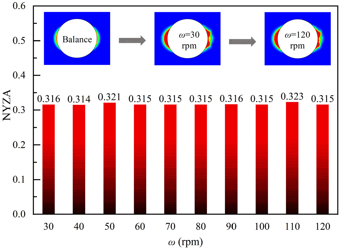
NYZA under the different spin velocity.
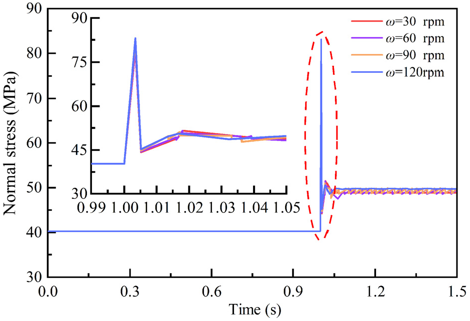
Normal stress under the different spin velocity.

Shear stress under the different spin velocity.
Effect of drilling tool size
In order to investigate the effect of drilling tool size on wellbore stability, according to the basic parameters listed in Table 1, the wellbore stability of a horizontal wellbore was simulated using the above-mentioned FEM model, and the size of different drilling tools, such as positive displacement motor (PDM), non-magnetic drill collar (NMDC), heavy weight drill pipe (HWDP), and drilling tool stabilizer, were compared, and its sizes were listed in Table 2. In addition, the drill-string was set with different lateral collision acceleration of 30–120g, a revolving speed of 60 rpm, and a friction coefficient of 0.1. Among them, the lateral collision accelerations of 30–120g were equivalent to an initial lateral velocity of 1.63–3.27 m/s, and the direction of the initial lateral velocity pointed to the right (the direction of maximum horizontal stress). The numerical simulation results were shown in Figure 20. Under the low acceleration of lateral vibration, there is a little difference on NYZA among different drilling tools, the drilling tool stabilizer has the minimum impact on the NYZA, and the other three kinds of drilling tools are very close to each other. However, under a medium to high acceleration of lateral vibration, there is an obvious difference on NYZA among different drilling tools, the influence of NMDC is the greatest, followed by PDM, HWDC, and stabilizer. On the one hand, because the size of PDM, Stabilizer, NMDC and HWDP were different, the momentum from the different drilling tool were different, while the acceleration of lateral vibration become higher, and it is obviously that the NMDC can provide the greatest momentum on the wall of wellbore. On the other hand, the lateral acceleration was applied according to the assumption of lateral acceleration is equivalent to an initial lateral velocity, the large size and heavy weight of drilling tool results in a larger lateral acceleration during the first collision period, so as the impact degree from the different drilling tools to the NYZA is NMDC > PDM > HWDP > Stabilizer.
Size of different drilling tools.


NYZA under the different size of drilling tools.
Discussions
As shown in Figures 10 and 13, both lateral acceleration and friction have significant impact on wellbore stability, the influence of lateral acceleration is usually greater than that of friction effect under a strong vibration condition, and the friction effect may be greater than that of lateral acceleration under a low vibration condition. In fact, these effects had been validated by theoretical and field studies. Regarding the influence of lateral acceleration on wellbore stability, Dykstra et al. 36 indicated that when lateral acceleration exceeds 50g, the collar in the pendulum assembly will whirl and impact the wellbore, and the interaction between the drill-string and wellbore aggravates drill-string vibration and further affects wellbore stability. Khaled 46 developed a model of critical vibration for the wellbore collapse, and analyzed some field cases, and they concluded that excessive lateral acceleration will cause excessive normal stress to wellbore rock. Regarding the influence of friction effect on wellbore stability, Skaugen and Kyllingstad 37 found that the friction effect between drill-string and wellbore can lead to a random vibration of drill-string, which may affect the drill-string collision on wellbore. Singh et al. 63 conducted numerical simulations on the wellbore instability induced by frictional interaction between drill-string and wellbore using torsional pendulum system, the results indicated that the friction effect between drill-string and wellbore aggravates the vibration of drill-string and cause to damage of surrounding rock. However, Singh et al. 63 indicated that friction changes dynamically during drill-string vibration, which depends on current slip velocity as well as nature of the sliding surfaces, and it conforms to the rate and state friction (RSF) model, but we employed the Coulomb’s friction law to characterize the friction effect between drill-string and wellbore in the present paper.
Regarding the influence of drill-string’s revolving speed on wellbore stability, as shown in Figure 17, the drill-string’s revolving speed almost has no influence on wellbore stability, this is due to uncoupled drill-string revolution and lateral vibration in the present paper. The reason to do so is to quantitatively determine the influence of a drill-string collision on wellbore stability, and the Khaled’s 46 simulation results also confirmed this assumption. In section 3.2, the lateral acceleration was applied according to the assumption of lateral acceleration is equivalent to an initial lateral velocity, in other words, the lateral acceleration and revolving speed are independent variables. Khaled 46 conducted a serious of simulation on drill-string collision, the drill-string is revolving in a wellbore with a diameter of 215.9 mm, and its revolving speed ranges from 60 to 220 rpm, as shown in Figure 21, the results indicated that the radial displacement of drill-string increased with revolving speed, and the revolving speed of 150 rpm is a critical value, the radial displacement doesn’t close to the wellbore radius when revolving speed <150 rpm, while it increase obviously when revolving speed >150 rpm, however, the drill-string never collides on the wellbore, so that the effect of drill-string’s revolving speed on wellbore stability can be negligible. However, the drill-string revolution and lateral vibration may be a coupled process during vibration, which may be inconsistent with the assumption of the lateral acceleration and revolving speed are independent variables, some of field measuring and simulation results had confirmed this phenomenon.36,42 Therefore, the relationship between lateral acceleration and revolving speed and its influence on wellbore stability should be further investigated.
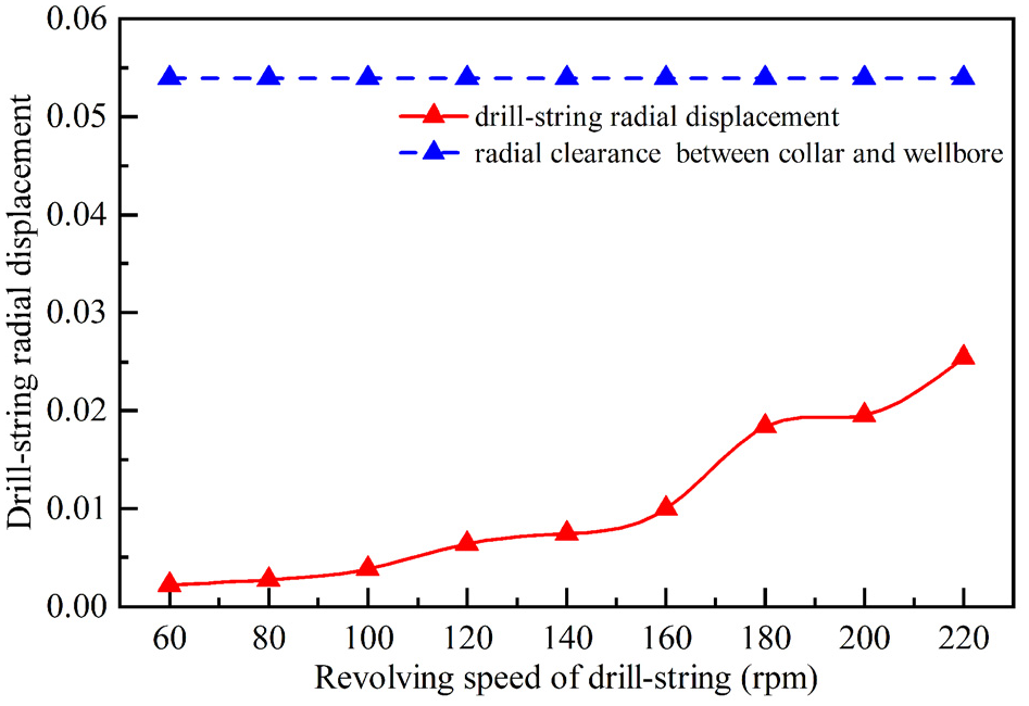
The effects of rotary speed on risk of wellbore stability. 46
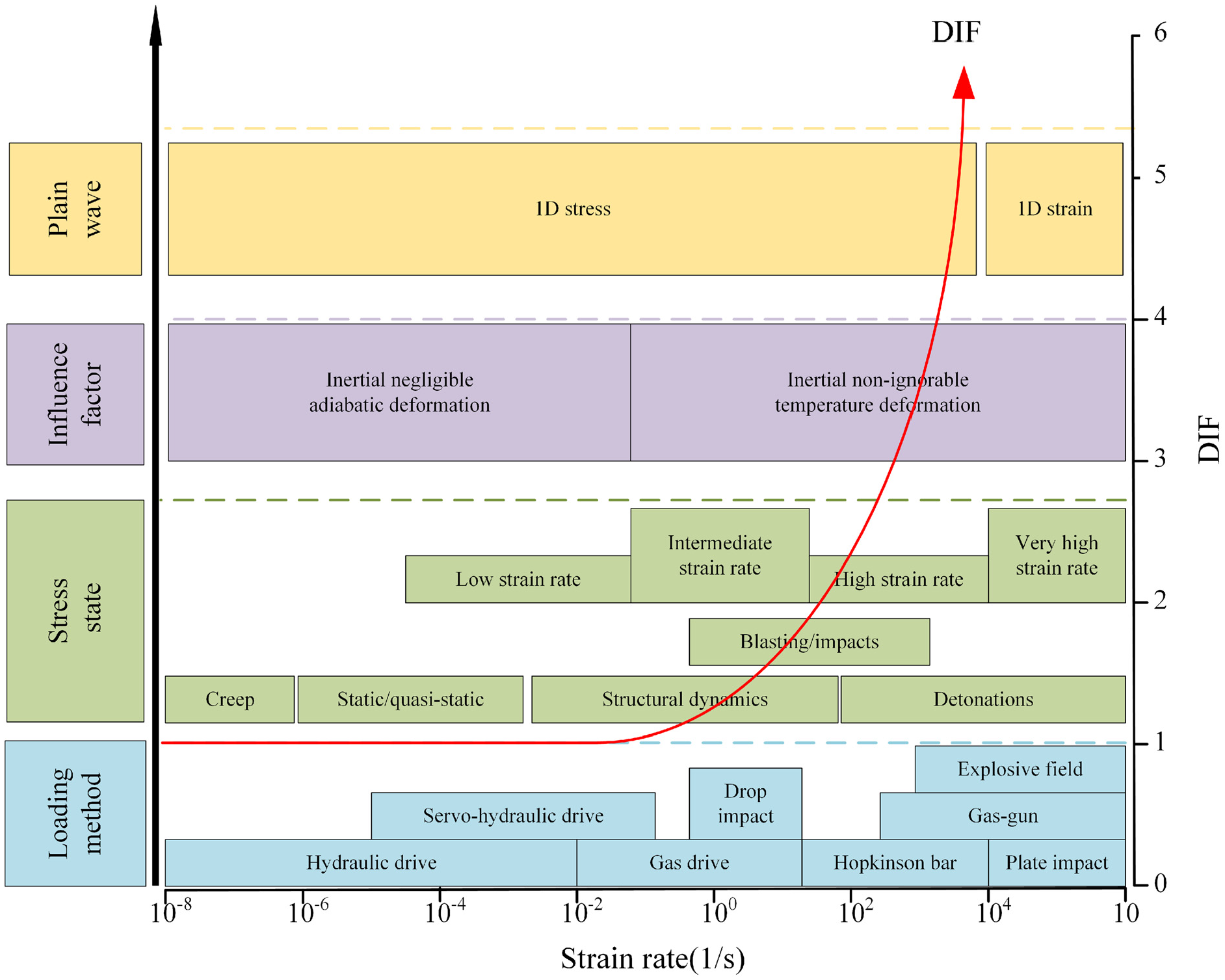
As shown in Figures 7, 11, 14, and 18, the lateral collision of drill-string is a typical dynamic problem encountered during drilling. Previous experimental and theoretical studies had confirmed that the dynamic strength of rock materials strongly depends on the loading rate,64–68 the divisions of strain rate with respect to engineering activities are shown in Figure 22. Meng et al. 65 and You et al. 66 classified loading rate into three typical cases, as shown in Figure 23, it is a static loading when the strain rate is lower than 5 × 10⁻⁴ s−1, a quasi-static or quasi-dynamic loading when the strain rate is between 5 × 10⁻⁴ s−1 and 1 × 10² s−1, and a dynamic loading when the strain rate is larger than 1 × 10² s−1. According to the numerical simulation results of normal stress, as shown in Figures 7, 11, 14, and 18, the strain rate ranges from 5 × 10⁻⁴ s−1 to 1 × 10² s−1, belongs to a typical quasi-static or quasi-dynamic loading, and the rock strength may be a strain rate-dependent strength, and the strain rate-dependent strength is usually greater than that of static. However, the strain rate-dependent strength was ignored in the present paper, so that the simulated NYZA may be overestimated, but it is more conservative and safer for actual drilling operations.
Stress state and experimental methods at different strain rates. 64

Divisions of strain rate with respect to engineering activities. 65
The failure patterns of wellbore rock are mainly the compressive or shear failures in the present paper, the main reason is excessive normal stress caused by lateral acceleration and friction during the first collision period, this phenomenon looks similar to literature. 44 Santos et al. 44 tried to analyze the effect of drill-string vibration on wellbore stability, and they concluded that the drill-string vibration directly destroys rock, when its stress exceeds the rock strength, and this case can mainly work when drill-string collides on the wellbore one time and applies stress above rock strength. However, Khaled et al.45,46 indicated that drill-string vibration can cause wellbore collapse by three typical failure patterns: (1) when drill-string vibration applies stress above rock compressive strength, rock compressive or shear failure will take place; (2) if drill-string vibration applies repeated cyclic loads on rock continuously, rock fatigue will occur; (3) if drill-string vibration cyclic loads on the rock are not strong enough to cause rock failure, rock fatigue will reduce rock strength and lead to rock compressive or shear failure. In the present paper, the rock fatigue and rock strength reduction induced by rock fatigue is ignored, and it should be further investigated in future.
In addition, the limitation of the present modeling can be concluded as follows: (1) the relationship between lateral acceleration and revolving speed was uncoupled, and its coupled influence on wellbore stability should be further investigated; (2) the strain rate-dependent strength was ignored, so that the simulated NYZA may be overestimated; (3) the rock fatigue and rock strength reduction induced by rock fatigue is ignored, so that the fatigue failure caused by drill-string vibration applies repeated cyclic loads on rock continuously cannot be investigated; and (4) the influence of wellbore pressure fluctuation, temperature and seepage effects are ignored. Therefore, the following aspects should be further investigated in the future: (a) influence of the coupled influence between lateral acceleration and revolving speed of drill-string on wellbore stability; (b) the influence of long-term drill-string collision at random on wellbore stability, especially drill-string vibration applies repeated cyclic loads on rock continuously; (c) influence of strain rate-dependent strength of rock materials on wellbore stability; (d) the influence of wellbore pressure fluctuation on wellbore stability; and (e) the comprehensive influence of wellbore pressure fluctuation and drill-string collision on wellbore stability.
Conclusions
Based on the theory of rock mechanics, drill-string dynamics, and FEM method, an elastoplastic damage FEM model was proposed for wellbore stability analysis of a horizontal well, and drill-string friction and lateral collision in the process of rotary motion were taken into account. An unconfined compression test was employed to verify this elastoplastic damage model, the numerical and experimental results of unconfined compression test are in consist, and the maximum relative error is less than 2.2%.
The evolution of NYZA caused by drill-string lateral collision can be divided into three typical stages: stage I (static balance), stage II (dynamic growth), and stage III (dynamic balance). In stage II, both normal and shear stresses reach to the peak value, the wellbore stability is then affected by drill-string lateral collision, and the NYZA therefore reaches the greatest value. Thus, after the first collision of drill-string on the wall of wellbore, there may be no significant impact on NYZA due to drill-string trends to be in revolution motion, consequently, both normal and shear stresses always fluctuate in a relatively small range in stage III.
Both lateral acceleration and friction have significant impact on wellbore stability, the influence of lateral acceleration is usually greater than that of friction effect under a strong vibration condition, and the friction effect may be greater than that of lateral acceleration under a low vibration condition. With the increase of friction coefficient, the NYZA increases almost linearly, and its linear fitting equation is NYZA = 0.2μ + 0.2952 (R2 = 0.9948). With the increase of lateral vibration acceleration from 30 to 120g, the NYZA increases nonlinearly, and the fitting equation is NYZA = 2.0 × 10⁻⁵a2 + 0.0003a + 0.2286 (R2 = 0.9899).
When the initial lateral velocity pointed to the wellbore lateral-side, its NYZA is obviously larger than that of the wellbore low-side. The fitting equation of NYZA under the collision position of wellbore low-side is NYZA = −6.0 × 10⁻⁶a2+0.0034a+ 0.1047 (R2 = 0.9927), while the fitting equation of NYZA under the collision position of wellbore lateral-side is NYZA = 2.0 × 10⁻⁵a2 + 0.0003a + 0.2286 (R2 = 0.9899).
The revolving speed of drill-string almost has no significant impact on NYZA, due to the relationship between lateral acceleration and revolving speed was uncoupled. Under the low acceleration of lateral vibration, there is a little difference on NYZA among different drilling tools, the drilling tool stabilizer has the minimum impact on the NYZA. However, under a medium to high acceleration of lateral vibration, there is an obvious difference on NYZA among different drilling tools, the influence of NMDC is the greatest, followed by PDM, HWDC, and stabilizer, because the NMDC can provide the greatest momentum on the wall of wellbore.
Footnotes
Handling Editor: Chenhui Liang
Declaration of conflicting interests
The author(s) declared no potential conflicts of interest with respect to the research, authorship, and/or publication of this article.
Funding
The author(s) disclosed receipt of the following financial support for the research, authorship, and/or publication of this article: This work was supported by the Sichuan Science and Technology Program (Grant No. 2020JDJQ0055), the Nanchong-SWPU Science and Technology Strategic Cooperation Foundation (Grant No. SXHZ033), and the Youth Scientific and Technological Innovation Team Foundation of Southwest Petroleum University (Grant No. 2019CXTD09).