
Abstract
This study aims to improve the power generation performance of the self-powered IoT turbine flowmeter developed in our previous study. To achieve this, a cone was installed at the front-center of the rotor to accelerate the water flow and streamline the resulting high-speed flow toward the blade near the periphery of the rotor. The experiments and flow simulations served to explore the effects of the cone on the characteristics of the flowmeter. The results demonstrate that both the power generated by the cone-equipped rotor and the pressure loss increases with increasing cone diameter
Introduction
Several studies have attempted to develop micro-hydraulic turbines that convert hydraulic energy in small rivers and drainage canals into electric power.1–8 Micro-hydraulic turbines with propeller-type rotors have been developed to utilize the water flow of the low head of less than 10 m.9–13 The transient stability of the water flow of each of the low-head pump stations is also investigated.14,15 Singh and Nestmann 10 and Tran and Kim 11 developed micro-hydraulic turbines that could be installed at drainage canals and the water circulation pipes in fish farms, respectively. We 12 developed a propeller-type micro-hydraulic turbine with excellent performance in terms of the passage of foreign matter included in the water flow. Du et al. 13 proposed a pump-turbine that realized pressure reduction and electric power generation simultaneously.
Electric power generation techniques that convert miniscule amounts of energy in the environment such as vibration and heat into electric power have attracted considerable attention.
16
Such energy harvesting techniques have been successfully used to supply electric power to sensors measuring temperature,
17
pressure,
18
and pH of water.
19
With recent advances in the energy harvesting, micro-hydraulic turbines can be effectively applied as power sources in sensors designed to detect the state quantity of the flow inside pipes. In order to obtain electric power necessary for the monitoring system of water leakage and water quality of various pipes such as water supply and drainage pipes, micro-hydraulic turbines for lift-force,20,21 drag-force,20,21 radial-flux,
22
and propeller type
23
have been developed. We have previously developed a turbine flowmeter with a power generation function.
24
The turbine flowmeter is connected to the pipes through which water flows, and the rotation of the rotor with four blades generates electric power. The generated power is used to operate a microcomputer and a low-power wide area (LPWA) communication module. The microcomputer detects the rotational speed of the rotor, and the LPWA communication module uploads the detected value to a server on the Internet. As the relationship between the flowrate and the rotational speed of the rotor is expressed by a linear function, the flowrate can be calculated based on the value of the rotational speed downloaded from the server. Thus, the flowmeter is a self-powered Internet of Things (IoT) sensor. A power of 0.245 W was obtained at a flowrate of 0.0012
In this study, we focus on improving the power generation performance of the self-powered IoT turbine flowmeter reported in the previous study. 24 A considerable amount of power is required to extend the IoT flowmeter to a multifunction sensor for monitoring various parameters that describe the state of water flow, such as the temperature and pressure. Therefore, in this study, a cone was introduced at the front-center of the rotor to improve the power generation performance. The cone accelerates the water flow at the front of the rotor and streamlines the resulting high-speed flow toward the blades near the periphery of the rotor. Such flow control using the cone can potentially increase the torque acting on the blades, thereby efficiently converting hydraulic energy into the rotational energy of the rotor. The experimental results showed that the introduction of the cone leads to an increase in the power output and power generation efficiency, while ensuring the linear relationship between the rotational speed of the rotor and the flowrate. The cone diameter corresponding to the maximum power generation efficiency was also determined. The effect of the cone on the power generation performance was also analyzed through a numerical simulation of the flow inside the rotor.
Turbine flowmeter and experimental setup
Self-powered turbine flowmeter and cone-equipped rotor
The self-powered IoT turbine flowmeter reported in the previous study
24
is based on the design of a previously developed micro-hydraulic power generator.
12
In this study, we aim at increasing the power generation performance of the turbine flowmeter by modifying the geometry of the rotor. Figure 1 shows the cross-sectional and 3D sectional views of the turbine flowmeter. The flowmeter is connected in series to the pipes through which water flows. A rotor with four blades is installed on the central axis of the flowmeter and is supported by two bearings. The axial length is 34 mm and the outer diameter of the blade is D=
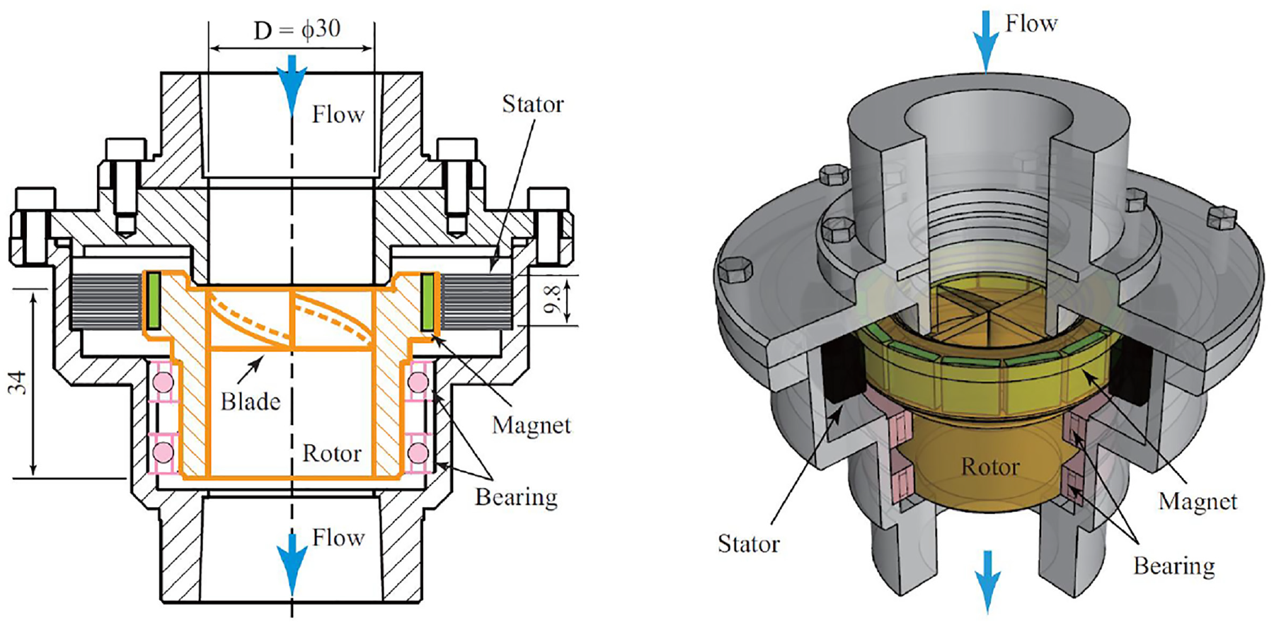
Cross-section of turbine flowmeter with power generation function.
The configuration of the blade of the rotor is shown in Figure 2. Figure 2(a) presents the geometry of the blade used in the previous study.
24
The four blades are joined on the axis of rotation. The blade geometry used in this study is shown in Figure 2(b). A cylindrical hub with a diameter
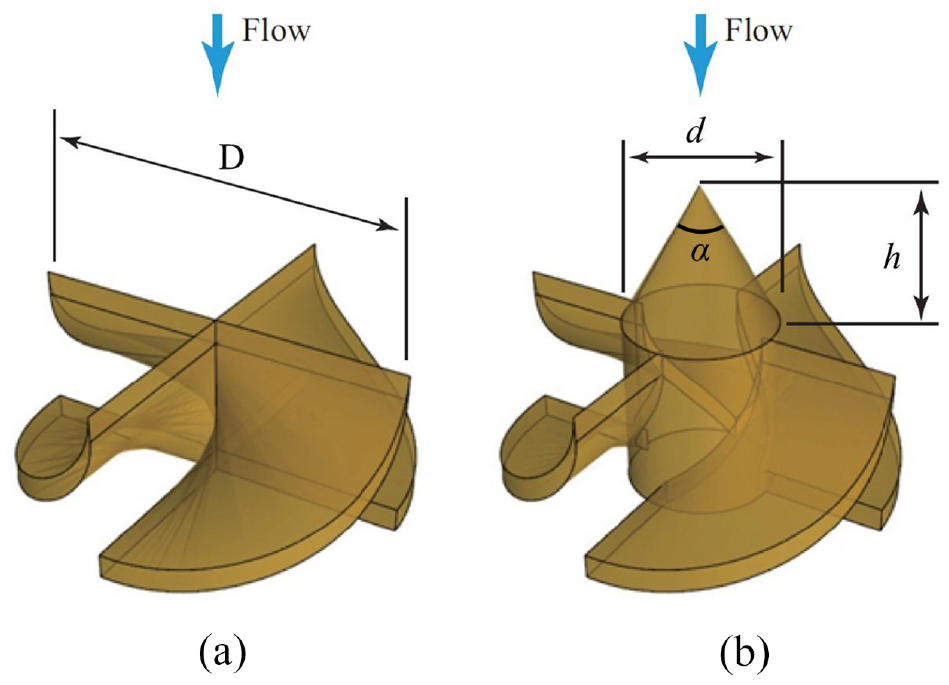
Configuration of rotor blade: (a) blade without cone and (b) blade with cone.
In this study, the cone height

Blade with a cone having various diameter.
Figure 4 shows the 2D development of the rotor blade at the periphery (

2D development of rotor blade (
As shown in Figure 5, the angles

Variation of angles
Power generation efficiency
The self-powered IoT turbine flowmeter is connected in series to water pipes. To measure the power generation efficiency, two pressure sensors, positioned 30 mm upstream and 75 mm downstream of the flowmeter, are attached to the pipes.
The power generation efficiency
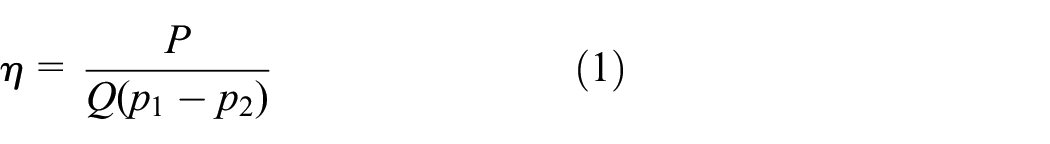
Here
Experimental setup
Figure 6 shows the experimental setup to investigate the power generation performance and the water flowrate measurement accuracy. Water is stored in a rectangular tank with a width, depth, and height of 790, 790, and 600 mm, respectively. The water pumped by a submerged pump passes through a commercially available electromagnetic flowmeter (FD-MH500A, KEYENCE CORPORATION). Then, the water flows into the turbine flowmeter to be tested and is finally released back into the tank. The water flowrate is controlled by the inverter drive of the pump.

Closed-loop test rig for laboratory experiment.
Experimental results and discussion
The power output of the turbine flowmeter

Effect of the cone diameter on relationship between water flowrate
Figure 8 shows the relationship between the water flowrate

Effect of cone diameter on the relationship between water flowrate
The upstream and downstream pressures of the flowmeter,

Effect of cone diameter on relationship between water flowrate
The power generation efficiency

Effect of cone diameter on power generation efficiency
Flow simulation
Simulation conditions
The power generation performance is closely related to the flow within the rotor. Thus, flow simulations were performed to explore the effects of the cone introduced at the front-center of the rotor on power generation performance. The simulation was performed using SCRYU/Tetra, a general-purpose thermofluid simulation software that uses a hybrid mesh to represent the surface shape of Software Cradle Co. Ltd. The fluid simulation was modeled on a Reynolds-Averaged Navier-Stokes (RANS) equation, whereas the turbulence is modeled with the
Figure 11 shows the simulation domain and the computational mesh. The finest mesh size was approximately 0.4 mm, which was used near the center of blades and the cone, and the coarsest mesh size was approximately 0.6 mm, which was used near the wall of the pipe. The domain consists of the flowmeter (generator) and the pipes 1.67D upstream and 1.67D downstream of the flowmeter, respectively. The domain is discretized with tetrahedron meshes. The number of meshes for the flowmeter is 910,000, and those for the upstream and downstream pipes are 11,000 and 56,000, respectively. The flowrate is prescribed at the upstream boundary, and the pressure is given at the downstream boundary. The no-slip condition is applied to all solid walls. The mesh on the blade surface is shown in Figure 12.

Computational domain and grid cells.

Grid cells on the blade: (a) blade without cone and (b) blade with cone.
In this simulation, the load torque of the rotor was adjusted so that the rotational speed of the rotor matched that used in the experiment. Currently, the error of power generation efficiency
Results and discussion
The water velocity distribution between the blades is shown in Figure 13. The distribution on a cross-section at a radial position of

Water velocity distribution between blades at
Figure 14 shows the pressure distribution on the same section as that shown in Figure 13. The pressure difference between the front and rear of the blade in the case of

Pressure distribution between blades at
The pressure distribution on the blade is shown in Figure 15. The pressures on the front and rear of the blade are plotted against the nondimensional distance
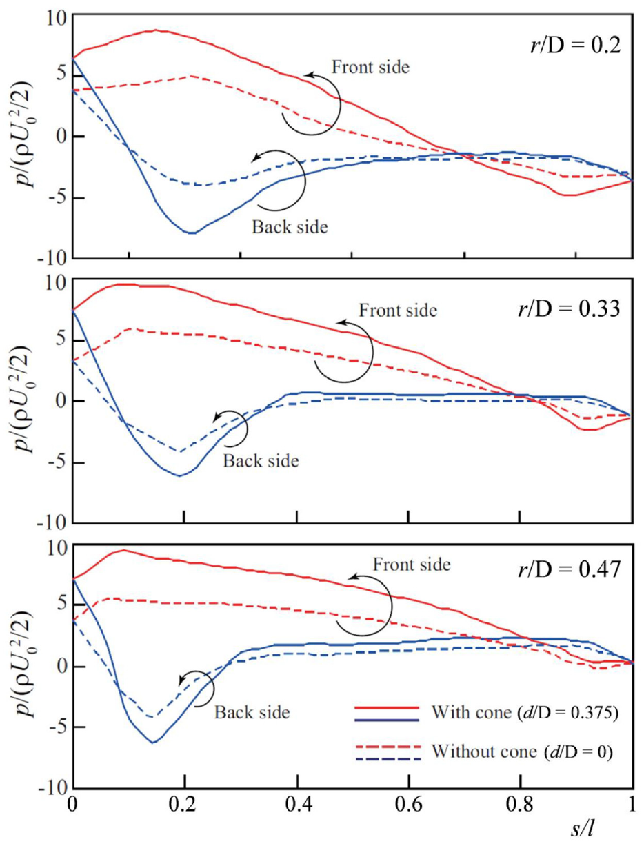
Pressure distribution on blade at
Conclusion
To increase the electric power generation performance of the self-powered IoT turbine flowmeter developed in a previous study, a cone was introduced at the front-center of the rotor. The effect of the cone diameter
(1) The power generated by the cone-equipped rotor increases with increasing
(2) The velocity between the blades of the rotor with the cone for
(3) The difference between the pressures on the front and rear of the blade for the rotor with the cone of
(4) The cone-equipped rotor facilitates the measurement of the flowrate because the relationship between the flowrate and the rotational speed of the rotor is expressed by a linear function.
Footnotes
Handling Editor: Chenhui Liang
Declaration of conflicting interests
The author(s) declared no potential conflicts of interest with respect to the research, authorship, and/or publication of this article.
Funding
The author(s) disclosed receipt of the following financial support for the research, authorship, and/or publication of this article: This study was partially supported by the grant-in-aid for the Project of Design & Engineering by Joint Inverse Innovation for Materials Architecture (