
Abstract
In the field of corrosion fatigue crack research, how to couple corrosion and fatigue under various conditions is a problem worthy of discussion. According to the electrochemical corrosion principles and the superposition principles, studies have been made on the interaction between corrosion and fatigue, and the relationship model between the corrosion fatigue crack size and the corrosion fatigue remaining life in the Corrosion of Hydrogen evolution (COHE) fatigue long crack growth stage is established. The feasibility of the model is verified by using the experimental data. According to the specific structure of the dislocation butt weld of large storage tank, the stress at the crack is calculated. Based on the above model and the experimental data, the corrosion fatigue residual life of large storage tank is predicted. The feasibility of the model is verified, which provides a new method for corrosion fatigue life prediction of large storage tanks.
Introduction
In real life, the materials of many machines and pressure vessel components are metal. The good physical properties of metal make it the mainstream of the era. However, in actual engineering practice, although the designer has no problem with the fatigue strength design, metal fatigue can still cause metal fracture to fail. 1
Corrosion fatigue is the result of the interaction of corrosion and fatigue loading, which is influenced by the corrosive environment, load magnitude and load frequency. Corrosion fatigue has been widely reported for testing in air and various environments. 2 In 2008, the Corrosion fatigue behavior of extruded magnesium alloy was discovered that corrosion fatigue crack initiation and crack initiation in an inert medium were completely different.2,3 The corrosion fatigue life was quantitatively evaluated by dividing the corrosion fatigue process into two phases, that is, the corrosion pit growth phase before crack initiation and the corrosion pit growth phase before specimen damage. 2 Studies were made on the influence of environmental factors on the corrosion fatigue of aluminum alloys, and based on fracture mechanics, crack growth was quantitatively characterized.4,5 In 2017, the mechanism of corrosion fatigue cracking was proposed. 6
In the corrosion fatigue crack growth stage, the interaction model believes that the rate of crack growth under the interaction of corrosion and fatigue will produce an additional crack growth rate.7–10 The competitive model considers the crack growth rate to be the one with the largest rate among them, but the independent superposition model considers them to act independently, the latter of which is difficult to establish in most cases. For instance, when electrochemical corrosion is Corrosion of Oxygen evolution (COOE), after the material produces a passivation film,11–13 the corrosion rate will be greatly reduced. Only fatigue cracks the passive film, and there must be a rate of interaction in this process.14–16 However, COHE does not produce a passivation film, and the independent superposition model is found to be applicable after verification in the case of COHE. In the research of corrosion fatigue, many people express the corrosion rate by Faraday’s law.17,18 Many scholars set the current density in Faraday’s law to be constant, but as the crack grows, Newman found that the current density changes, 9 but it needs to be determined by continuously measuring the corrosion potential. It can be done when doing corrosion fatigue experiments, but it is obviously unrealistic to measure low-cycle corrosion fatigue at all times for decades.12,19 This article studies the corrosion potential through the chemical properties of the corrosion solution.
In the stress analysis of thin-walled cylindrical pressure vessels, many people think that the stresses received by cracks in different directions are hoop stress and axial stress,20–24 the calculation method is adopting the analysis method of thin-walled cylinders. Some people would also think that the crack stress analysis of large liquid storage tanks is still obtained by the analysis method of thin-walled cylinders.25–27 However, this method is based on the condition that the pressure in the cylinder is equal everywhere. However, the pressures of different liquid levels in large-scale liquid storage tanks are completely different, and there is no pressure on the upper surface, so the thin-walled cylinder method is not suitable for calculating the stress of large-scale liquid storage tanks.28–30 In this paper, the stress state at the crack is studied based on the combined cylinder method.
This article is structured as follows: Firstly, by analyzing the difference between the two kinds of electrochemical corrosion of COHE and COOE, it is analyzed that the principle of independent superposition is different in the two cases; Secondly, according to the chemical properties of the solution, based on Paris formula and Faraday’s law, combined with the principle of independent superposition, the relationship model between corrosion fatigue crack growth rate and crack size is established; Then, based on the combined cylinder method, the relationship between the stress at the crack and the crack size is established, and the life of the oil tank is predicted; Finally, some conclusions are drawn.
Research method
Process of corrosion fatigue
The corrosion fatigue life of materials is divided into two main periods. The first period is from the smooth specimen to the formation of corrosion pits and growth to the critical pit depth. At this time, fatigue small cracks are generated under the effect of stress concentration, and the multiple small cracks expand and coalesce into long cracks. This stage is the initial corrosion fatigue life of materials. The second stage is the stage from the appearance and propagation of long fatigue crack to the fatigue fracture failure, which is the corrosion fatigue long crack propagation life of materials. 15 In this paper, the growth of long cracks is mainly studied. Schematic diagram of corrosion fatigue process is shown in Figure 1.
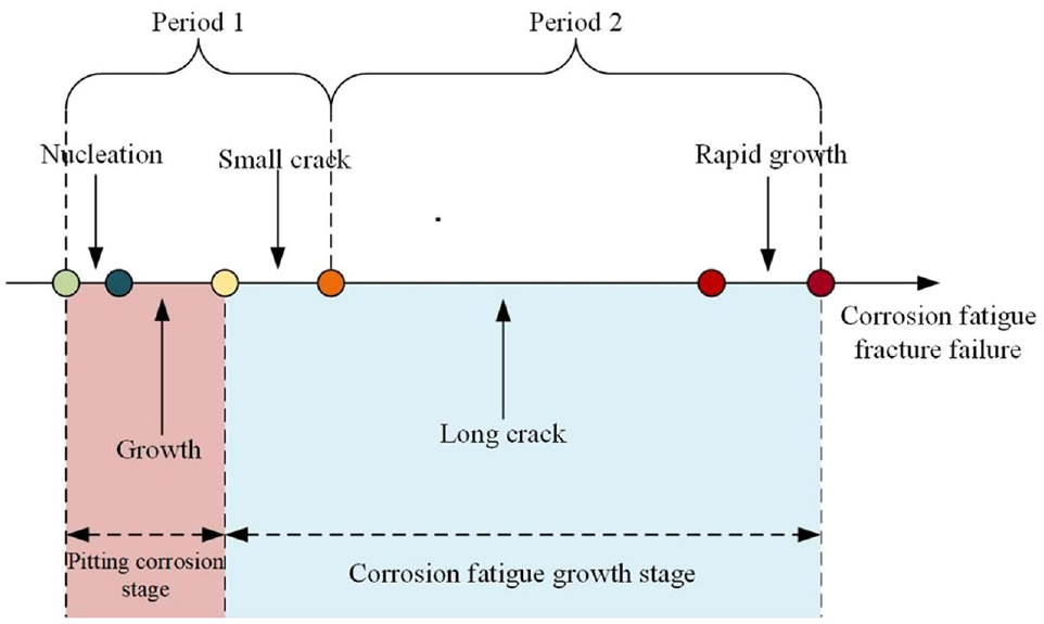
Corrosion fatigue process.
Corrosion rate of COHE during fatigue long crack growth
Different from the electrochemical corrosion in the crack initiation stage, the fatigue crack growth rate in the crack propagation stage is faster, and the surface of the fresh crack tip is constantly exposed. Electrochemical corrosion is divided into two types: COOE and COHE. COOE will produce a passivation film, that is, the commonly known rust, whose chemical composition is
The corrosion rate is usually measured by Faraday’s law13,14:

where
Fatigue growth at the long crack growth stage
The fatigue crack propagation stage generally refers to the process of material crack propagation in the air to rapid fracture. 17 The crack growth rate in this stage is very regular. The Paris model is a well-known and recognized crack growth rate model in the fatigue crack growth stage 32 :
Thereinto pure fatigue of

where
Generally, the metal material will have a stress intensity factor threshold value for crack growth

Of course, this crack growth stage will also end. When the crack size reaches a certain value, it will enter a rapid fracture period. At this stage, the crack grows very rapidly, and this crack size is called the critical crack size

Thereinto

where

Bringing into the above formula is as follows.

where
COHE fatigue long crack growth rate
Electrochemical corrosion is divided into COHE and COOE.COOE has a fast corrosion rate, but produces a passivation film that slows the corrosion rate. COHE will not produce a passivation film to reduce the corrosion rate, but the corrosion rate is slower. 19 The superposition model of interaction assumes that there is an interaction between corrosion and fatigue, resulting in an additional rate of interaction.
For example, COOE will produce a passive film, the composition of which is

Corrosion of oxygen evolution.

Corrosion of hydrogen evolution.
The rate of this period is not a simple sum of the two, because the corrosion rate is 0, and the fatigue rate acts on another material, with the rate unknown, so the passive film will certainly produce a corrosion fatigue interaction rate
The current density is the decisive factor, and the rest are constant. Due to factors such as corrosion deposits and metal activity, the current density of the crack wall is much smaller than the current density of the crack tip, 21 and the constantly exposed surface of the fresh crack tip becomes the target of corrosion. Therefore, the corrosion current density generally refers to the current density of both the anode crack tip and the cathode coating. 9 Many scholars regard the current density as a constant, that is, the corrosion rate will not change from beginning to end. But the metal loses electrons from the anode through the solution to the cathode, and the cracks become deeper and deeper, so the length of the solution will also become longer, and the resistance of the electrons will also become larger. The crack tip displacement will also change with the crack depth and stress, which will affect the current density. 27 Stress and crack depth will affect the current density, and there will be no passivation film after COHE, so there is no need to quickly dissolve the width of the crack tip.
So during COHE, the stress also has an effect on the corrosion current. This also creates an interaction, which accelerates the rate of crack expansion. The superposition of the corrosion fatigue interaction rate and the corrosion rate is expressed as 27 :
where
Therefore, the total rate of corrosion fatigue is:

However, we know the current density changes, but we need to constantly measure the current density or voltage. It may be possible to do it in experiments, but if there lie ahead decades of low-cycle corrosion fatigue, it is difficult to make measurements all the time. The PH-potential diagram of

PH-potential diagram of
Model validation
In engineering practice, there are many failures of mechanical parts when they work, mainly due to defects caused by corrosion, fatigue and corrosion fatigue.34,35 Therefore, in the process of mechanical component design and acceptance, it is necessary to evaluate and modify according to the actual situation. For example, when the wall of a large storage tank has defects, the remaining service life should be evaluated based on corrosion fatigue cracks for repair and replacement. 36 If it is working at a high temperature, the theoretical strength should be improved. It can be seen from the Paris formula that the fatigue growth rate increases exponentially as the crack size increases.
If the current density is constant in Faraday’s law, then
According to data from the literature, 37 compare the data it gets with the data in Figure 5.

Relationship between crack size and crack growth rate of COHE.
It can be seen that in the case of corrosion fatigue with only COHE, the nonlinear model is closer to the test data, while the linear model and the test data have larger errors. Compared with the three curves in the graph, the nonlinear model is closer to the experimental data, which verifies that the nonlinear model is more reasonable.
Life prediction of liquid storage tank
The material of oil storage tank is Q245R, which is low carbon steel. Schematic diagram of tank wall and surface crack is shown in Figure 6. Both elastic modulus and yield stress are related to temperature. The relationship between elastic modulus and temperature is shown in Figure 7. And the relationship between yield stress and temperature is shown in Figure 8. 17

Schematic diagram of tank wall and surface crack.

The relationship between elastic modulus and temperature.
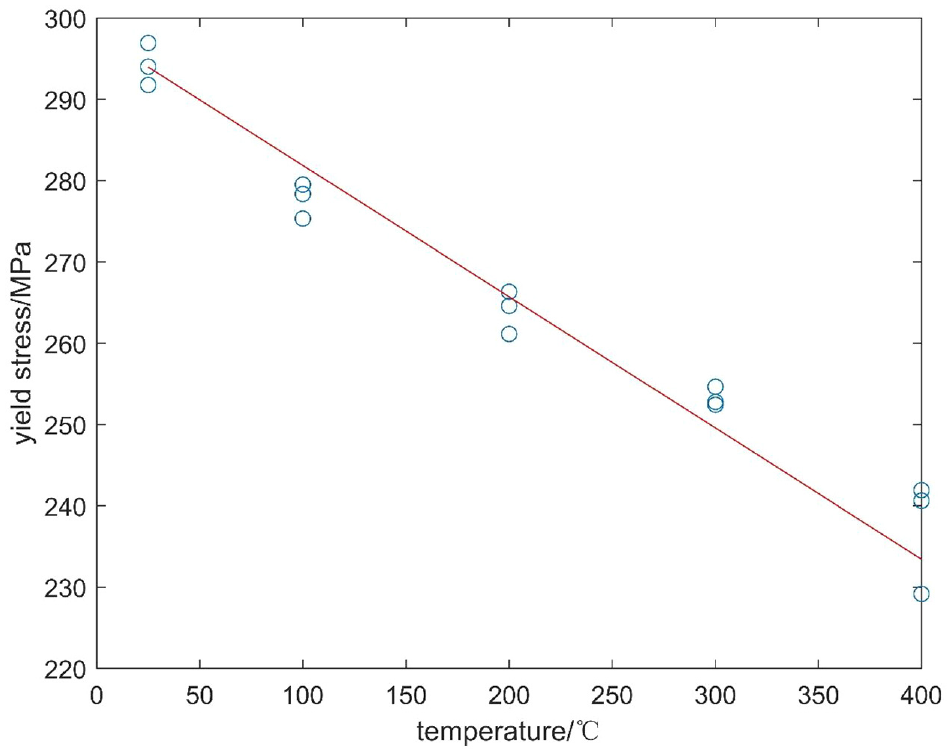
The relationship between yield stress and temperature.
The relationship between yield stress and temperature is as follows:
When it is known that at

The temperature of this area is about 40°C in summer, and the critical crack depth
Related parameters.

The oil tanks in this article have been tested and all of the crack defect locations is shown in Figure 9. The Figure 10 shows the deepest flaw on the tank wall. In order to obtain the size of the crack, we polish it off, which is shown in Figure 11.

Crack defect location.

Crack 9.

Polished crack 9.
Tank wall stress calculation of liquid storage tank
Most storage tanks are equipped with floating roof seals. This kind of internal pressure storage tank is regarded as a thin-walled cylinder by some scholars.
39
The axial stress is
The detection crack is horizontal, so it is not subject to circumferential stress. The pressure of the tank wall changes with the height of the liquid storage. The pressure of each place is different, so the stress of different height also varies. Schematic diagram of the pressure distributions of large oil storage tank shell is shown in Figure 12. The bottom plate is separated from the tank bottom according to the shear effect of the upper side wall plate on the lower side wall plate. 38 These are considered to be a long cylindrical shell wall plate, the model as shown in Figure 13, on the edge of the unit force and under the action of hydraulic pressure, the deflection equation, respectively.


Schematic diagram of the pressure distributions of large oil storage tank shell.
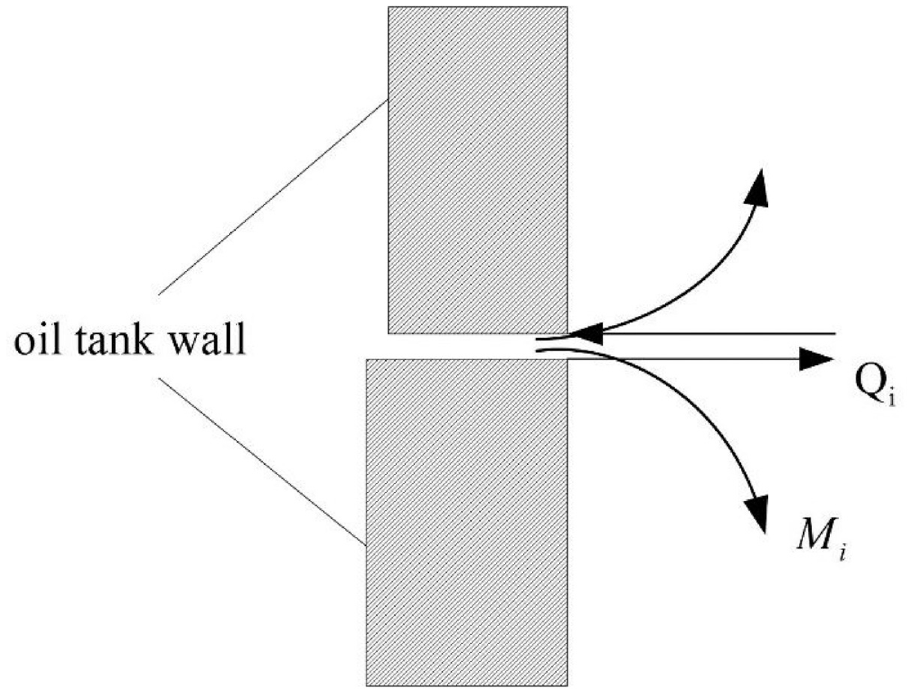
Schematic diagram of shear force and bending moment of the crack.
where
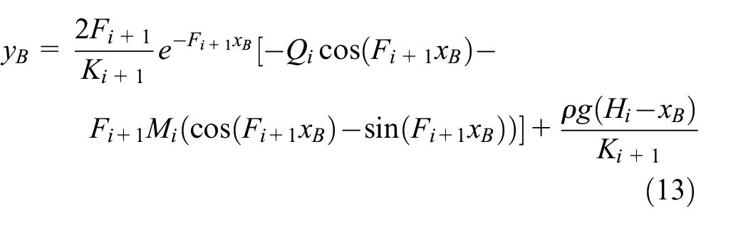
where
When

Considering that the result of calculation of the bending moment
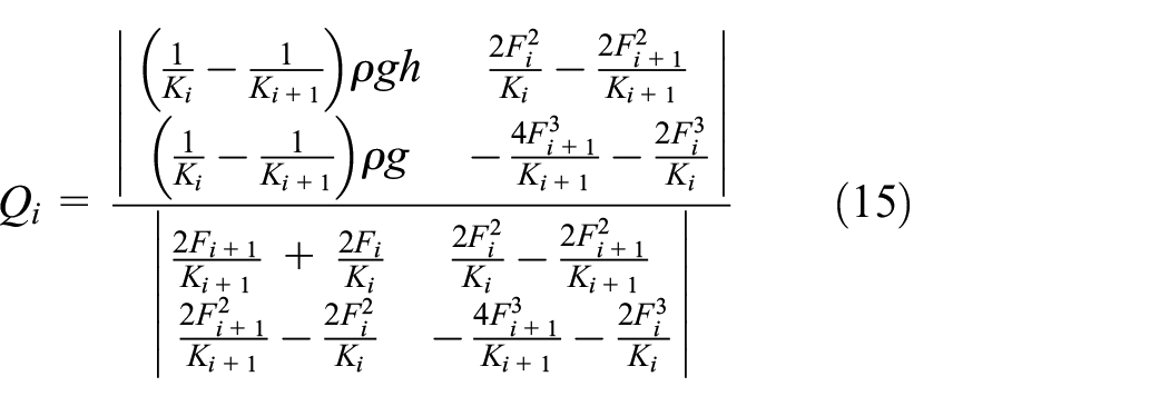
Therefore, the shear force on the tank wall whose width is the crack length (

Schematic diagram of tangential stress of the crack.
Schematic diagram of crack surface length and depth is shown in Figure 15. The crack section is generally a semi-ellipse, where


Schematic diagram of crack surface length and depth.
For cracks in storage tanks, the relationship between crack length and depth can be introduced 39 :

The stress intensity factor is 26 :

where
Generally, the deepest and longest cracks detected are at the weld seam, and the butt joint of the weld seam will cause stress concentration. Schematic diagram of weld place is shown in Figure 16, so the stress concentration factor of the butt weld seam is introduced 28 :

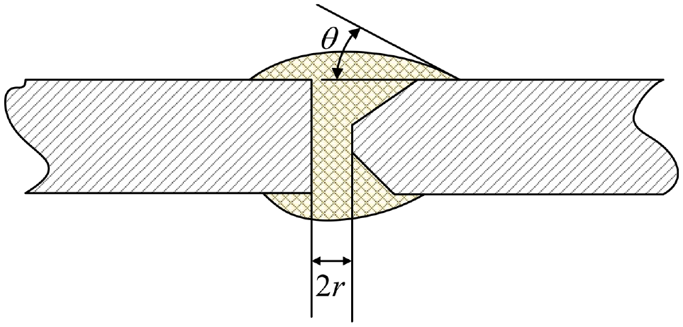
Schematic diagram of weld place.
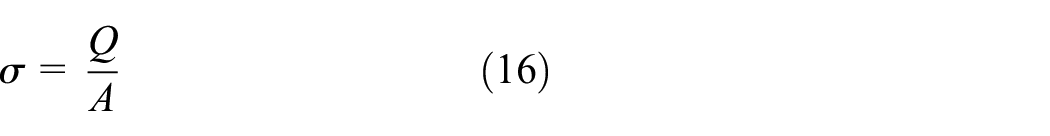
The maximum shear stress is:

where
The deepest part of the crack is at the welding point between the first and second tank wall. Apply the model to calculate the stress at the deepest part of the oil tank wall crack, which is 121.04 MPa.
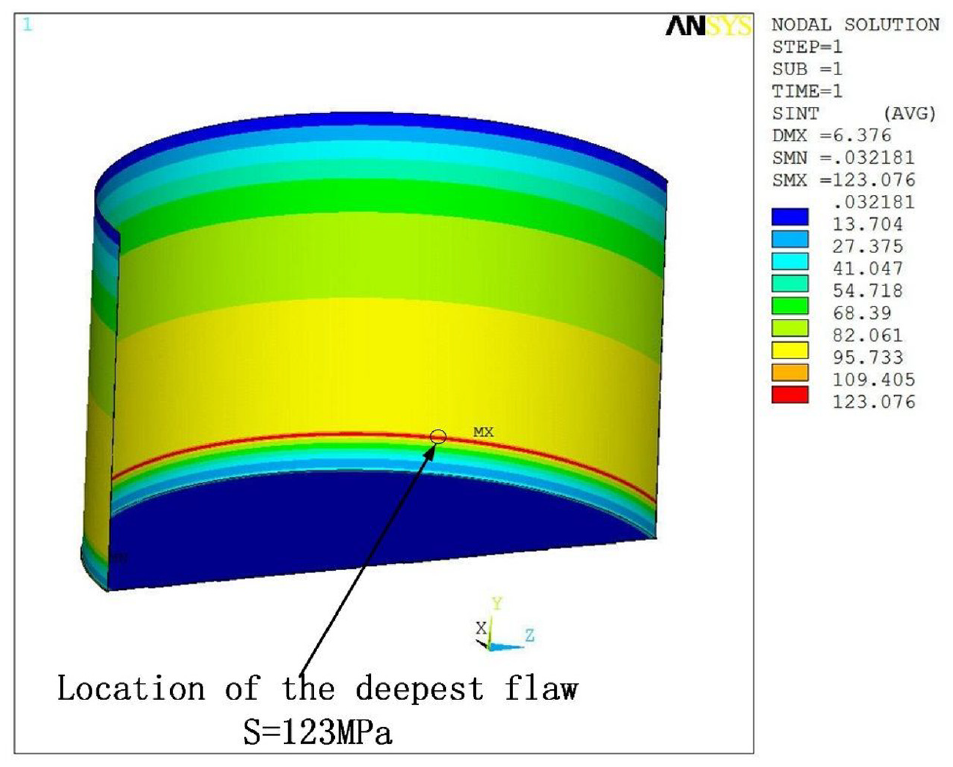
In order to enhance the accuracy of the calculation, the finite element method is used to calculate the stress here. Stress analysis nephograms are shown in Figures 17 and 18. The establishment of the finite element solution shows that the stress between the first wall and the second wall is 123.076 MPa, and the error is only 1.6%. This calculation result verifies the accuracy of the model. When predicting the life of an oil tank, the model is used to calculate the stress of cracks at different depths.

Overall Stress analysis nephogram.
Partial Stress analysis nephogram.
The parameters of the oil tank are brought into the corrosion fatigue of the material of the model Q245R.
It can be seen from Table 2 that the theoretical remaining service life of the pressure vessel is about 9.78 years, which is basically the same as the design remaining service life of 10.25 years, and the error between the design service life of the gasoline storage tank and the measured data is only 4.51%.
Comparison of predicted life and actual service life.

Conclusion
In this paper, based on the Paris formula, the relationship between corrosion solution current density and crack depth in the corrosion fatigue process is investigated in the COHE case, and a nonlinear crack expansion model is established. Comparing the steel corrosion fatigue crack expansion rate under linear and nonlinear models, the results show that the nonlinear model is more suitable for the prediction of corrosion rate. Establish the relationship between crack stress and crack size at the weld seam according to the actual tank condition. The applicability of the model is verified by predicting the remaining service life of the tank, and the error is within 5% from the actual situation. A new method for reservoir life prediction is proposed.
Footnotes
Handling Editor: Chenhui Liang
Declaration of conflicting interests
The author(s) declared no potential conflicts of interest with respect to the research, authorship, and/or publication of this article.
Funding
The author(s) received no financial support for the research, authorship, and/or publication of this article.