
Abstract
Uneven coatings with overspray often occur to the target plate when using a pneumatic atomizer. This issue is mainly due to the high-level pressure in the plate center, which results from unreasonable design of the structure and operating parameters in atomizer. In this paper, an optimal design for these parameters was established by response surface method (RSM) and computational fluid dynamics (CFD) to produce more uniform coatings. The velocity data measured by a hot-wire anemometry experimentally verified the numerical model. Then, annular air hole diameter, horn flare angle, annular air pressure, and shaping air pressure were selected as design variables while the central pressure was chosen as objective function. The RSM with the central composite design (CCD) was employed to construct the regression equation that expresses the relationship between the central pressure and design parameters. Finally, the optimum combination of the parameters was carried out for reducing the central pressure, and the interaction effects between the parameters were also analyzed. The optimization results show that the central pressure is decreased by 44.6% and the performance of droplet size distribution is significantly improved. The experiment confirmed the effectiveness of the optimized atomizer to obtain well-distributed coatings.
Keywords
Introduction
Pneumatic atomizers are widely used for surface coatings and manufacturing of new materials with peculiar properties. They can provide better atomization characteristics, along with the ultrafine coatings that result in a remarkable improvement of protective and esthetic properties, especially in the painting industry.1–3 In contrast to other types of spray painting, such as airless atomizers, and rotary bell atomizers, the gas flow field of the pneumatic atomizer exerts excessive pressure on the central region of the target plate, which will bring about overspray, painting liquid sagging, and lower transfer efficiency.4–7 As the key factor in the spray coating process, the homogenization of the pressure distribution on the plate directly affects the formation of the uniform coatings. However, local high-level pressure often occurs to the plate because of the unreasonable design of the geometrical structure and operating conditions in atomizer. Therefore, the liquid paint is easily concentrated in the plate center, which leads to uneven coatings with the overspray happening from time to time.8–10 To solve this problem, a repeatable and comprehensive design for the pneumatic atomizer must be done, which means the interactions between the influential factors should be considered simultaneously. 9
Many experimental and numerical investigations on spray coatings using the pneumatic atomizer have been carried out in recent years,11–14 referring mainly to the influence of the geometrical structure and operating conditions. Fogliati et al. 15 analyzed the mechanism of spray deposition by computational fluid dynamics (CFD) to predict paint droplet trajectories and film builds on the target plate though the secondary breakup of droplets was not considered. They investigated the influence of the rectangular target plate and its orientation on the paint film thickness. Further, some researchers focused on more complicated target plates, such as the inclined plane, 16 concave stepped surface, 13 and inner or outer cylindrical surface, 17 to fit in unforeseeable working situations. In terms of the operating conditions, Ye and Pulli 13 studied the effects of the atomizing and the shaping air flow rate on the droplet size distribution. Li et al. 10 found that increasing shaping air pressure was beneficial to even coatings. Whereas an increment in horn flare angle would aggravate the uneven coatings due to the too high pressure in the plate center. They also pointed out that the greater the center pressure was, the easier it was to cause overspray. Wang et al. 8 proposed a double-nozzle atomizer and thought that uneven coatings with overspray easily happened when the distance between the two paint holes and the angle between the axes of the paint holes were both small. Conversely, the coating film shape became a concave that would slightly cause uneven coatings. In summary, many scholars devoted much to promoting the painting performance of the pneumatic atomizer from different individual aspects, and studies of other types of air atomizers on spray characteristics had been also performed.2,18–21 However, the interaction effects of the structure and operating parameters on the spray coating were rarely mentioned. Besides, lots of time and cost will be spent on the experiments and simulations for these issues due to insufficient samples for accuracy improvement. Therefore, only using experiment or simulation means to optimize the parameters of the atomizer can hardly improve the uniformity of spray coating as a whole. It is necessary to employ the optimization methodology to design the atomizer comprehensively.
Response surface methodology (RSM) is a multidisciplinary design optimization method that combines statistical mathematics and computer technology. This technique can be used to determine the relationship between various design parameters and the desired responses with the advantages of design cycle-shortening and experimental cost-saving.22–24 Some scholars have tried to apply this technique to the fields relevant to the optimization of spray coatings.25,26 For example, Müller and Kleinebudde 27 especially conducted a complete 32 factorial design of experiment (DOE) to correlate the atomization and pattern air pressure with the spray width using RSM. An optimal atomization air/pattern air ratio of atomizer for a good coating process has been found. In the research of Seyedin et al., 28 in order to optimize the coating mass of particles in a top-spray fluidized bed coating, they adopted RSM to conducted an experimental investigation. The effect of the fluidization air flow rate, atomization air flow rate, and liquid flow rate on the coating mass was determined by using DOE. Additionally, other scholars have optimized the structure of spraying equipment in this way, such as Wang et al. 29 They combined the RSM technique and the non-dominated sorting genetic algorithm to perform a CFD-based multi-objective optimization design for the structural and operating parameters of the self-excited oscillation nozzle, aiming at improving the jet atomization quality.
To the authors’ knowledge, there are inadequate investigations concerning the optimization of design parameters of a pneumatic atomizer with multi-hole structure, which plays a vital role in improving spray coating quality. Therefore, in this paper, based on RSM technique, an optimal design for the structure and operating parameters in atomizer was developed with the help of the commercial CFD solver, aiming at reducing the local high pressure on the target plate and producing well-distributed coatings. This study effectively optimizes the pneumatic atomizer and provides reliable technical guidance for the design of the nozzle in the future.
This paper is organized as follows. In “Numerical setup” section, the atomizer geometry, the mathematical model and the numerical methods are explained. A hot-wire anemometry measuring system is built to measure the gas velocity for proving the numerical model is reliable. “Application of response surface method” section shows the application process of the RSM for optimizing the atomizer. “Results and discussion” section includes the statistical evaluation of the regression equation and the analysis of the response surface graphs. The central pressure and the droplet size distributions before and after optimization are discussed. “Confirmation experiments of spraying coatings” section conducts the experiment to confirm that the RSM-based optimal design of the atomizer is feasible. “Conclusions” section summarizes the conclusions.
Numerical setup
Pneumatic atomizer geometry
The structure of the pneumatic atomizer consists of paint hole, annular air hole, auxiliary air holes, and shaping air holes as shown in Figure 1, where

Pneumatic atomizer geometry (
Structure parameters of pneumatic atomizer.


Spray coating process using a pneumatic atomizer.
Mathematical model
Gas phase
The gas phase in the spray flow field is governed by the fundamental conservation law, namely the continuity and momentum equations. The prediction of the gas flow field was obtained by solving the time-averaged Navier–Stokes equations and combining with the appropriate closure model for turbulence. The most commonly used model is
Discrete phase
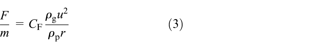
The spray flow field can be seen as gas-liquid two-phase flow that is described by the discrete particle model (DPM). DPM is a multiphase flow model based on the Eulerian–Lagrangian method, which is used to simulate the movement of droplet particles in the gas phase. The gas governing equation is solved as a continuous phase in the Eulerian coordinate system, and the liquid droplet particles are regarded as a discrete phase in the Lagrangian coordinate system. 31 The motion equation of a particle is expressed as:

where
The Taylor analogy breakup (TAB) model, used to analyze the droplet oscillation and the secondary breakup,32,33 is shown as:

where


where
Coating film
The Eulerian wall film (EWF) model was employed to calculate the distribution of the coating film thickness on the targe plate.16,35 When the liquid droplets in the spray flow field impinge on the plate and deposit to form a coating film, the mass and momentum of the liquid phase are removed from the two-phase flow and added as source terms to the mass and momentum conservation equations of the liquid film, respectively. Therefore, the thickness of the coating film can be calculated through the mass and momentum conservation equations of the liquid film.17,36
The mass conservation equation of the film is

where

where
The momentum conservation equation of the film is

The terms on the left represent the transient and convection effects, respectively. On the right hand, the first term involves the effects of gas-flow pressure, the gravity component normal to the wall surface, and the surface tension; the second term represents the effect of gravity in the direction parallel to the film; the third term is the viscous shear force at the gas-film interface; the fourth term represents the viscous force in the film, where

where
Computational domain and numerical methods
As shown in Figure 3, a cuboid block of 400 mm × 200 mm × 200 mm was used as the computational domain. The atomizer is located in the center of plane ABCD. The distance from the atomizer to the target plate EFGH is 194 mm. As shown in Figure 4, unstructured meshes were chosen to discretize the three-dimensional computational domain, which could better fit the complex geometry of the atomizer. Local mesh refinements around the nozzle axis, elliptical spray cone, and the target surface were carried out. Sparser meshes were used in the region far away from the nozzle. As such, it can improve the calculation accuracy and reduce the consumption of computing resources.

Schematic diagram of computational domain.

Mesh in the plane YZ of the computational domain.
The pressure-based solver and the semi-implicit method for pressure linked equations (SIMPLE) algorithm were employed in ANSYS Fluent. The turbulent kinetic energy and turbulent dissipation rate were both set as first-order upwind, and the other variables used second-order upwind. Pressure-inlet boundary conditions were set at annular air hole, auxiliary air holes, and shaping air holes. The target plate EFGH and the nozzle surface were set as no-slip wall boundary conditions. The other boundaries (planes ABFE, CDHG, ADHE, BCGF, and ABCD) were set as pressure-outlet conditions. The pressure-inlet boundaries for the atomizer holes were set the same as the initial operating parameters in the laboratory, which was shown in Table 2. The outlet pressure was set to 1 atm.
Operating parameters of pneumatic atomizer.

In previous studies,10,16 the initial condition of discrete phase in the spraying simulation was determined like this: the velocity and size distribution of droplets were measured by experiments that are expensive and time-consuming; then, the discrete phase was added at the inlet of paint hole to simulate the primary atomization when the liquid was assumed to be totally atomized. After that, the TAB model was used to predict the secondary breakup and the child droplets’ diameters. According to references,8,10 after the computational results of gas phase tend to convergence, 120 non-Newtonian liquid particles at the paint hole were injected into the gas flow field. These particles have a diameter of 65 μm with Rosin–Rammler distribution and an initial velocity of 10 m/s (i.e. flow rate of 300 mL/min for the paint hole). The important properties of the materials used here were presented in Table 3. Moreover, the formation of the liquid film was simulated by EWF model when droplets impinge on the plate. The spraying time was 0.4 s and as such this numerical method can simulate the spray coating process.
Properties of the paint and air.

According to the initial simulation works, it was found that a grid system with about 7–16 million cells can take into account both higher accuracy and computational cost. Specifically, grid systems with 7.4, 9.7, 13.2, and 15.8 million cells were created to conduct the grid independence test, as shown in Figure 5. The effects of four different grid systems on the gas velocity and pressure distribution along Z-axis were both analyzed. When the number of cells is more than 13.2 million, the velocity and pressure curves remain basically unchanged, which means the calculated results are convergent and independent of the number of cells. Considering the computational time and cost, the grids with 13.2 million cells were adopted for the simulation.
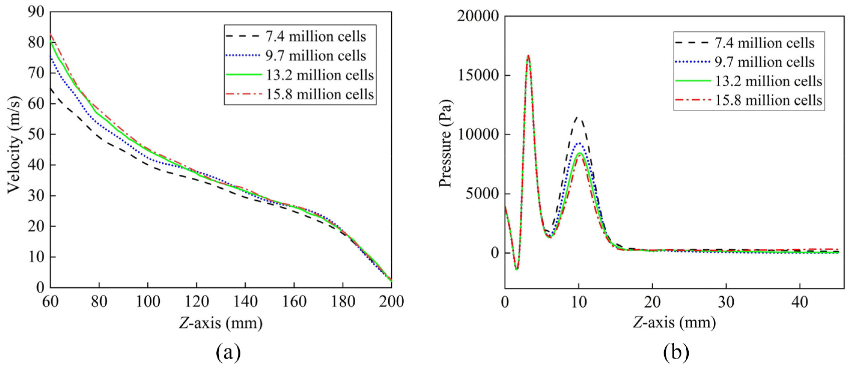
Grid independence test: (a) gas velocity along Z-axis and (b) pressure distribution along Z-axis.
Experimental verification for spray flow field
Simulation results of the gas flow
Simulation contours for velocity and pressure distribution of the gas flow are presented in Figure 6. Gas velocity distributions on the planes YZ and ZX (Figure 6(a) and (b)) show that the high-speed gas sprays out from the multi-holes and converges with each other. Then, the gas-flow spreads to the target plate EFGH in a flat elliptical cone shape. Finally, the gas flows out along the plate and forms an oval uneven pressure area on the plate (Figure 6(c)) with the highest pressure of 307.95 Pa, which will intensify the uneven coatings in the spray coating process.

Simulation results of gas flow: (a) velocity contour on plane YZ, (b) velocity contour on plane ZX, and (c) pressure contour on the plate EFGH.
Experimental setup and verification
As shown in Figure 7, to validate the reliability of the numerical model, a hot-wire anemometry measuring system, mainly composed of air source system, hot-wire anemometry (Dantec Dynamics A/S, Copenhagen, Denmark), and traverse system, was set up to obtain the velocity data of gas flow field. The gas source was provided by an air pump (FB-420/7, Shanghai Jiebao Compressor Manufacturing Co., Ltd., Shanghai, China). The airflow pressure was measured by the piezometer. The temperature of laboratory environment was kept at 25°C. The experimental operating conditions were conducted the same with the numerical simulation as shown in Table 2. Before measurement, the velocity calibration with the range of 0–100 m/s was conducted. Then, the velocity data acquisition was accomplished by the hot-wire probe. Moreover, the traverse coordinate system, controlled by a computer automatically, was used to move the probe in the space. The areas that need to be measured include the planes ZX and YZ (shown in Figure 3).

Hot-wire anemometry measuring system: (a) schematic diagram and (b) experimental setup.
Figure 8 shows the quantitative comparisons of the experimental and calculated gas velocity evolution along the X-axis and Z-axis (in the plane ZX), respectively. With increasing the distance

Comparison of experimental and calculated gas velocity evolution: (a) gas velocity along the X-axis (L is the distance between the measuring cross-section and the nozzle) and (b) gas velocity along the Z-axis.
Application of response surface method
Crucial design parameters
The pressure distribution on the target plate is affected by the structure and operating parameters of the pneumatic atomizer that are shown in Tables 1 and 2. The size of annular air hole influences the flow rate of the spray gas, which is the main reason for local excessive pressure on the plate. The horn flare angle will influence the spatial distribution of the spray flow field and the pressure distribution on the plate.10,13 Besides, the annular and shaping air pressure determine the liquid break-up process and the atomization performance. The ovality of painting area is related to shaping air pressure. If the annular air/shaping air ratio is too low, a dumbbell pattern can be formed.
27
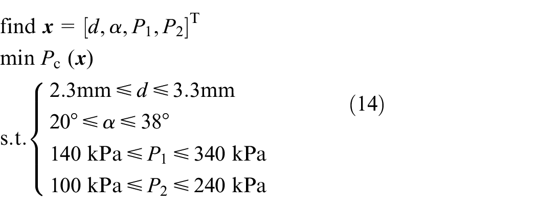
Therefore, these crucial factors including annular air hole diameter
The design parameters and their levels.

Objective function
Since the high-level pressure occurred to the plate center is the incentive of uneven coatings, the optimization of coating quality can be converted into the homogenization of the pressure distribution. As shown in Figure 9, the pressure region with a value greater than 90 Pa (colored as red) considered here will result in uneven coatings on the plate. The area-weighted average is more reasonable than the mass-weighted average in the uneven distribution.
29
Hence, the central pressure


Pressure area with the value greater than 90 Pa.
where
Central composite experiment design
The objective is to find a mathematical regression equation that can approximately model the objective function (the central pressure
Experimental design and corresponding results.

Regression equation
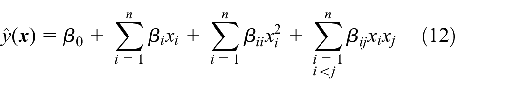
The relationship between the central pressure

where
where

Results and discussion
Analysis of regression equation
To examine the accuracy and validity of the regression model developed above, an analysis of variance (ANOVA) was presented in Table 6. The main criterion used to check the fitting accuracy of response surface regression model is the complex correlation coefficient
ANOVA table for the regression model.
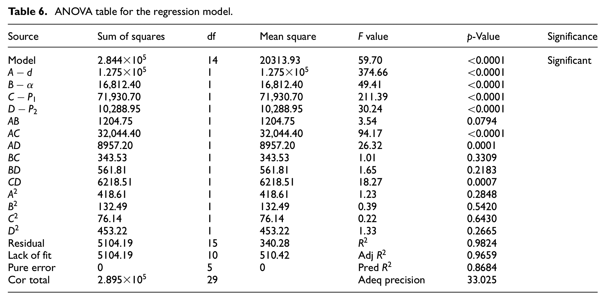
Table 6 shows that the regression model formed for the central pressure
In addition, Figure 10 shows the externally studentized residuals of the central pressure

Normal plot of residuals for the central pressure.
Interaction effects of design parameters
With the aforementioned statistical analysis, it is concluded that the response surface regression model given in equation (13) is well fitted and valid within the ranges of the design parameters. Hence, the model can be used to predict the changing trend of the central pressure

Interaction effects of

Interaction effects of

Interaction effects of

Interaction effects of

Interaction effects of

Interaction effects of
From Figure 11, it can be seen that the central pressure
Figure 14 shows the change of the central pressure
From above discussion about the interaction effects of the design parameters, the characteristics of the impacts of each individual parameter and combined parameters on the pressure distribution can be roughly clarified. Compared with the other two parameters, annular air hole diameter
4.3 Optimization model
For alleviating the uneven coatings by reducing the local high-level pressure on the target plate, the central pressure
The desirability function approach (DFA) incorporated in Design Expert software is one of the most important and extensively utilized techniques for the optimization of various responses.38,39 Using this method, the optimization problem was solved by employing the regression model (equation (13)) of the objective function obtained previously. Among the groups of solution results with lower central pressure, three candidate solutions that have suitable desirability were preferably selected. Then, the optimization results of central pressure
Candidate solutions and result verification.

The comparisons between the predicted results obtained by RSM and the simulation results of CFD show that the maximum relative error is 3.47%. It is indicated that the regression model established in this study, relating to the objective function and the design parameters, is reliable, which can approximately substitute the CFD calculation.
Optimization results and discussion
Referring to Table 7, and considering the complexity of the atomizer structure and the controllability of the operating conditions, the optimum combination of the design parameters in atomizer was determined as follow: annular air hole diameter
The atomizer parameters before and after optimization as well as the corresponding central pressure
Comparison of the atomizers before and after optimization.

Figure 17 shows the development of the spraying process when using the optimized atomizer. It took about 3.4 ms for the droplets to spray from the nozzle to reach the target plate. After 7.6 ms, the spraying pattern of the coatings on the plate was basically formed.

Development of the spraying process when using optimized atomizer.
According to references9,40 unevenness in spray coatings is mainly related to the atomization performance. The smaller the droplet diameter is, the more the amplitude of the unevenness is decreased. To verify the optimized atomizer can improve the atomization performance and the uniformity of coatings, the size and the corresponding number of the droplets that impinge on the target plate were collected and counted when the spraying time reaches 0.4 s. The droplet size distributions of the original and optimized atomizer were derived from the calculation under the same boundary conditions. As shown in Figure 18, before the optimization, the droplet sizes mostly distributed in the range of 30 to 65 μm, taking a percentage of 79.9%. This indicates that most of the droplets have a large size range, which is not conducive to the uniformity of droplets on the plate. However, the optimized atomizer could produce finer droplets with a diameter of around 35 μm due to the adequacy and homogenization of the airflow diffusion in the space. These tinier droplets account for about 37.2% of the total number, which deposit on the plate to help form a uniform and dense coating.

Comparison of droplet size distributions on the plate for original and optimized atomizer.
Confirmation experiments of spraying coatings
After the structure and operating parameters of the optimized atomizer were determined, the final step is conducting the experiment of spraying coatings to confirm the effectiveness of the optimized atomizer. The air cap of the optimized atomizer that was fabricated in machining workshop is shown in Figure 19(b). The experiment apparatus for spraying coatings was consists of air source system, paint supply system, and traverse system, as sketched in Figure 20. The atomizer was mounted on the bracket and its direction was vertically downward. The target plate that was placed under the atomizer is steel. By using the terminal device, the atomizer can be moved up and down through the traverse system. The distance between the atomizer and the plate was adjusted to 200 mm. The red paint was transported by the diaphragm pump, and its flow rate was controlled to 300 mL/min by a liquid flow meter. By controlling the piezometers, the annular air pressure and the shaping air pressure for the original and optimized atomizers were adjusted to the values that were shown in Table 8.

Air cap of the pneumatic atomizer: (a) original and (b) optimized.

Experimental apparatus for spraying coatings: (a) schematic diagram and (b) experimental setup.
The snapshot of the spraying coating process captured by a high-speed camera (Fastcam MiniAX100-C, Photron, Tokyo, Japan) when using the optimized atomizer is shown in Figure 21. The spraying time lasted for 2 s, which was timed by a stopwatch. After the coatings on the steel plate had dried out, the thickness distributions were measured by the magneto-inductive method using a coating thickness gauge (Beijing Saibo Ruixin Technology Co., Ltd., Beijing, China). When measuring the coating film thickness along the X-axis, the measuring points were taken at an interval of 10 mm. At each point, the thickness was measured five times, and the average value was taken as the thickness. Finally, the obtained thickness value divided by 5 was seen as the coating thickness at the spraying time of 0.4 s.

The spray coating process captured by a high-speed camera.
The thickness value derived from the simulation is that of the wet coating film. When compared to the measured data of the dry coating film, the thickness of wet coating film should be converted to the dry one through the following equation 41 :

where
Figure 22 compares the simulated and experimental spray patterns of the original and optimized atomizers. The shape and the size of simulated coating film are similar to that of experimental results for both two atomizers. Compared with the original atomizer, the optimized one has a wider spray range, which can not only avoid the overspray to get a more uniform coating but also improve the spraying efficiency.

Comparison of the simulated and experimental coating film: (a) original and (b) optimized atomizer.
The thickness distributions of the dry coatings along the X-axis obtained from the simulation and experiment for both original and optimized atomizer are compared in Figure 23. The measured data with standard deviation are slightly lower in the center and higher on both sides than that of the simulated results for two atomizers. The main reason is that the wet painting would slightly spread to both sides under the effect of gravity during the drying process. Nevertheless, the simulated results of dry coatings still show general agreement with the experimental data. Additionally, no matter for the simulation or the experiment, the coating thickness distribution of the optimized atomizer spreads out more uniformly than that of the original one. Specifically, it was assumed that half of the maximum coating thickness along the X-axis is the effective painting film in the simulation. 8 As such, the effective coating lengths of the original and optimized atomizer are 71.5 and 110.4 mm, respectively. The effective coating length is increased by 54.4% after the optimization design, expanding the range of spray coatings. The experimental data show similar behavior. The results discussed in the confirmation experiment illustrate that the RSM-based optimal design of the pneumatic atomizer developed in this paper, for obtaining a more uniform coating, is feasible.

Dry coating thickness distributions along X-axis of the simulation and experiment for original and optimized atomizers.
Conclusions
When using a pneumatic atomizer, the local high-level pressure occurred to the target plate is the incentive of uneven coatings. An optimal design for the structure and operating parameters in atomizer has been performed to produce a well-distributed coating by reducing the central pressure
The velocity data measured by the hot-wire anemometry experimentally verify the numerical model, which lays a foundation for later optimization study. The ANOVA results show the regression model is valid and significant since the
The response surface graphs illustrate the interaction effects of the design parameters on the central pressure
The optimization results obtained by DFA are in good agreement with the simulation results of CFD, which indicates that the regression model can substitute the numerical simulation. The optimized result of design parameters is determined as follow: annular air hole diameter
After RSM optimization, the atomizer can produce finer droplets with a diameter of around 35 μm, depositing on the plate to form a more uniform coating as well as alleviate the overspray. The confirmation experiment indicates that the simulated coating thickness distributions agree with the experimental data. The effective coating length of the optimized atomizer is increased by 54.4%. Thus, the optimal design of the atomizer developed in this paper can facilitate the uniform coatings and provide industry reference for optimizing pneumatic atomizers.
Footnotes
Handling Editor: Chenhui Liang
Declaration of conflicting interests
The author(s) declared no potential conflicts of interest with respect to the research, authorship, and/or publication of this article.
Funding
The author(s) disclosed receipt of the following financial support for the research, authorship, and/or publication of this article: This work was supported by the Natural Science Foundation of Zhejiang Province (Grant No. LR21E060001) and the National Natural Science Foundation of China (Grant No. 11872352).