
Abstract
Experimental investigations of the condensation and evaporation of R410A on the outside of two double-side enhanced heat transfer tubes were conducted, and the tube performance was compared with that of a smooth copper tube. The research object consisted of a smooth tube with a length of 2000 mm and an outer diameter of 25.4 mm and two double-side enhanced tubes of the same size. The evaporation experiments were run under the following conditions: the evaporation saturation temperature was 7°C, water inlet temperature was 8°C–18°C, and water flow rate was 0.6–1.6 m3/h. The condensation experiments were run under the following conditions: the saturation temperature was 35°C, water inlet temperature was 21°C–30°C, and water flow rate was 0.4–1.6 m3/h. During the data processing, the heat transfer coefficient of the water side was obtained using the Gnielinski-Wilson method, and that of the refrigerant side was obtained using the thermal resistance separation method. The effect of the surface structure on the heat transfer performance was analyzed, and a strengthening measure was proposed. The experimental results indicate that the evaporation heat transfer coefficients outside the smooth tube increased with the raise of the inlet water temperature, while the double-side enhanced tubes decreased; both the condensation heat transfer coefficients outside the smooth tube and the enhanced tubes increased with the increase of the water flow rate. Due to the different type of enhanced tube ribs, tube #3 surface structure is more conducive to the formation of vaporization core, which is about 30% higher than the outer heat transfer coefficient of tube #2. It is more in line with the requirements of strengthening horizontal single tube external pool boiling heat transfer. In the condensation experiment, the condensation heat transfer coefficients outside the smooth tube increased with the raise of the inlet water temperature, while the double enhanced tubes decreased; both the condensation heat transfer coefficients outside the smooth tube and the enhanced tubes increased with the increase of the water flow rate. With the analysis of the rib structure, the outer surface structure of tube #2 has stronger drainage capacity, and the external average condensation heat transfer coefficient is about 7% higher than that of tube #3, which is more in line with the requirements of condensing heat transfer outside the single tube.
Introduction
Among the alternative refrigerants of R22, R410A is one of the refrigerants with the closest thermodynamic performance to that of R22; it is near azeotropic and exhibits a high compression efficiency. 1 As early as 2001, by measuring the heat transfer coefficient and pressure drop of the evaporation and condensation of R22 and R410A in two types of inner spiral grooves, Goto et al. 2 determined the influence of tube type on the heat transfer coefficient and pressure drop. The local heat transfer coefficient of the herringbone grooved tube was better than that of the spiral tube under either condensation or evaporation conditions. In 2009, Kapadia et al. 3 used R22 and R410A to study the transient characteristics of an independent air conditioning system, and found that the total transient loss ratio of the R410A system was 18.5%, while the transient loss ratio of the R22 system was 18.7%. Under the same working conditions, the R410A system has a lower transient loss because of refrigerant migration. Zhao et al. 4 studied the heat transfer of several refrigerants outside the enhanced tubes at 35°C using three copper porous tubes with a diameter of 16 mm and a thickness of 1.5 mm. They found that as the heat flux increased, the boiling heat transfer coefficients of these refrigerants increased, and at the same heat flux, the boiling heat transfer coefficient of R410A was greater than those of R134a and R22. Furthermore, at the same heat flux, the total heat transfer coefficient of R134a was 1.08–1.10 times that of R22, and the total heat transfer coefficient of R410A was 1.28–1.37 times that of R22. In contrast, the total heat transfer coefficient of R407C was only 0.80–0.81 times that of R22. There exists a large difference in the boiling performance of different refrigerants on the outside of tubes with the same enhancements.
Enhanced heat transfer technology has been gradually attracting extensive attention in the field of refrigeration. The utilization of various enhanced tubes has allowed the development of heat exchange equipment characterized by compactness, high efficiency, and low cost. 5 Therefore, the development of advanced heat exchanger tubes is of great significance for increasing the efficiency of heat exchange equipment. The geometric parameters of the double-side enhanced tube fins make the heat transfer more complex. To develop new types of high-efficiency heat exchangers, the structural parameters of enhanced tubes should be studied thoroughly. Developing various surface-enhanced tubes is an effective way to increase the efficiency of the condenser and evaporator. 6
After much research by many scholars, it has been found that the tube type and structural parameters of the enhanced tube have a significant influence on the heat transfer effect. In 2007, Ma et al. 7 determined the condensation heat transfer of R245fa outside a three-dimensional enhanced tube. The results indicated that, in comparison with the value calculated by the Nusselt model, the condensation heat transfer coefficient of R245fa on the smooth tube was higher and that of the three-dimensional enhanced tube was approximately 10 times that of the smooth tube. Therefore, the heat transfer capacity of the three-dimensional enhanced tube was significantly improved. In 2011, Takahashi et al. 8 performed a comparative study of three different shapes of three-dimensional and two-dimensional enhanced tubes. In the high heat flow range, the external condensation heat transfer coefficient of the three-dimensional enhanced tube was approximately double that of the two-dimensional enhanced tube. In the low heat flow range, the external heat transfer coefficient of the enhanced tube with the minimum fin density was the highest. In the same year, Kukulka et al. 9 developed many new style vipertex EHT tubes. The scaling rate of the enhanced tubes was slightly slower than that of the bare tubes. Therefore, the surface design can effectively inhibit fouling in the tubes and heat exchanger swelling during long-term use. This type of pipeline exhibits a more stable performance and a longer service life. In 2014, Ma et al. 10 further compared and studied the condensation heat transfer characteristics of R134a outside four two-dimensional enhanced tubes and two three-dimensional enhanced tubes based on previous work. They found that the condensation heat transfer coefficients of R134a outside the two-dimensional enhanced tube and the three-dimensional enhanced tube were 11 and 19 times that of the smooth tube, respectively, and summarized the optimal range of structural parameters. In 2017, Li et al. 11 studied the condensation heat transfer performance of two three-dimensional enhanced tubes. For condensation, the 2EHT-2 tube produced a higher heat transfer efficiency than that of the 2EHT-1 tube at the same flow rate and saturation temperature.
In 2017, the pool boiling heat transfer of refrigerant R134a outside three enhanced tubes was experimentally studied by Ji et al. 12 The results showed that the total heat transfer coefficient of the enhanced tube was three times that of the smooth tube. However, when the heat flux was less than a certain amount, the total heat transfer coefficient of the enhanced tube was lower than that of the common tube. Therefore, the enhanced tube does not have the effect of heat transfer enhancement under all working conditions. In 2018, Xu et al. 13 studied the boiling heat transfer characteristics of HFO1234ze outside smooth tubes and three enhanced tubes. The results showed that the heat resistance outside the tube was significantly greater than that inside the tube. Therefore, it is important to enhance the boiling heat transfer performance outside the tube and reduce the heat resistance outside the tube to increase the total heat transfer coefficient of the boiling heat transfer. In 2019, Zhao et al. 14 considered the heat transfer characteristics of falling film evaporation of two types of three-dimensional fin bilateral enhanced tubes with R245fa as the working fluid. According to the experiments, in comparison with the theoretical surface heat transfer coefficient of the smooth tube, the heat transfer enhancement ratio of the Y-tube was 2.12–2.94 and that of the T-tube was 2.48–2.98 and 2.58–3.00, respectively. In the same year, Sun et al. 15 tested the saturated flow boiling heat transfer and pressure drop of R410A outside smooth tubes, herringbone tubes, and 1EHT tubes, focusing on the effects of mass flow rate, dryness, width, and surface structure on heat transfer. It was proved experimentally that the pressure drop and evaporation coefficient increased with an increase in the mass flow rate under certain conditions. In comparison with the smooth tube, the 1EHT tube exhibited superior thermal performance.
Many researchers have conducted analyses and research on the condensation and evaporation heat transfer of different working media in different pipe types.16–22 However, because of their complex surface structure, currently, there exists no theoretical solution model for the three-dimensional heat exchanger tube. Therefore, experiments are still the main method for evaluating their performance.23–26 Hence, it is important to identify a suitable condensation and evaporation enhancement tube for R410A. In this study, two types of three-dimensional low-rib double-side enhanced tubes were applied to the flow condensation and evaporation heat transfer experiments of R410A. The heat transfer performance of the various tubes was compared to determine the tube type that is more suitable for the flow condensation and evaporation heat transfer of R410A, and to analyze its mechanism to further improve the tube structure.
Experiments
Experimental set-up
This test bed integrates the condensation and boiling heat transfers of a single tube. A schematic of the experiment is shown in Figure 1. The entire experimental system is composed of four parts: a refrigerant cycle, front-end heat transfer cycle, test section cycle, and back-end heat transfer cycle.

Schematic of experimental system.
The refrigerant circulation system consists of a diaphragm pump, pulse damper, mass flowmeter, plate heat exchangers, sight glass, test section, electromagnetic expansion valve, drying filter, and reservoir. For the condensation tests, the subcooled refrigerant is driven by the diaphragm pump to HE1 where it is heated and evaporated. The liquid refrigerant flows back to the reservoir after being subcooled in HE3. The refrigerant liquid throttled by the electronic expansion valve flows to the reservoir and repeats the next cycle. During the evaporation test, the subcooled refrigerant passes through HE1 without any heating in the test section, and the vapor refrigerant is condensed in HE3 and the liquid flows back to the reservoir. A water-glycol loop is composed of an electric heater, a water pump, a constant-temperature water tank, valves, and so on. It mainly cools the heat exchanger HE2 and the liquid reservoir in the test section to the required temperature for the experiment. The water circulation system in the experimental section includes a plate heat exchanger HE2, a water pump, and an electric heater. The Reynolds number of the cooling water is used to characterize the experimental conditions of the cooling water. The cooling water exchanges heat with the glycol aqueous solution in the plate heat exchanger HE2 to remove the heat released by the refrigerant condensation in the system.
Tube geometry
The test section represents a casing heat exchanger, where the water flows inside, while the refrigerant flows outside of the tube. The test tube consists of a smooth tube and two different types of enhanced tubes, the outer diameter is 25.4 mm and the effective heat transfer length is 2000 mm. The cross section of two bilateral enhanced tubes are shown in Figure 2(a) and (b). The two enhanced tubes are made of the same size of the smooth tubes; the difference lies in the structure of the surface on both sides of the tube. Tube #2 is straight rib outside the tube and trapezoidal thread inside the tube; tube #3 is T-shaped fin outside the tube, and triangle thread inside the tube. The outer surface of the test section is wrapped with a thermal insulation layer, reducing the heat leakage loss between the test section and external environment.

(a) Longitudinal section of exchange tube #2. (b) Longitudinal section of exchange tube #3.
Test conditions
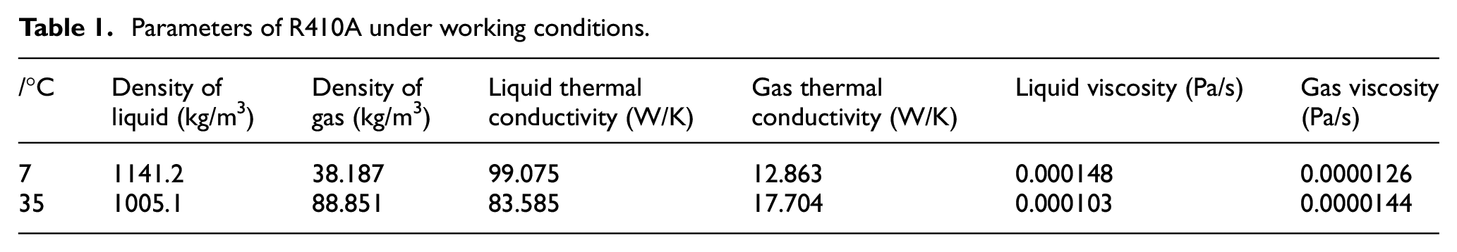
R410A was selected as the refrigerant in the test, and its physical parameters are listed in Table 1. The evaporation experiments were run under the saturation temperature of 7°C, and the water inlet temperature was 8–18°C, with the water mass flow set to 0.6–1.6 m3/h. The condensation experiment was conducted under the following conditions: the condensation saturation temperature was 35°C, water inlet temperature was 21°C–30°C, and water mass flow rate was 0.4–1.6 m3/h.
Parameters of R410A under working conditions.
Data processing and error analysis
Data processing
The refrigerants at the inlet and outlet of the experimental section remain in a single-phase state. The heat transfer of refrigerant evaporation is as follows:

Heat transfer of water:

where hrin and hrout are the refrigerant enthalpies calculated according to the measured inlet and outlet temperature and pressure of the test section, respectively, in kJ/kg; twout is the outlet water temperature, and twin is the inlet water temperature, in °C.
The heat transfer rate Qa was expressed as

The heat balance was calculated by

In this study, only when n < 3% was the obtained data considered valid. Total heat transfer coefficient of test section K is calculated as:

where A0 is the surface area of the test tube (m2), and △tm is the logarithmic mean temperature difference, in °C.
Separation method
The Wilson method is based on the power relationship between the total heat transfer coefficient and water flow rate; however, this method has some errors for the double-side enhanced tube. The Wilson-Gnielinski method uses the pressure drop to calculate the Nusselt number first and then calculates the convective heat transfer coefficient in the tube. This method can be applied to the experiment of fluid Reynolds numbers in the range of 2.5 × 10³–1 × 10⁶.
The Wilson-Gnielinski formula 27 is as follows:

Where Prf is the Prandtl number calculated according to the average fluid temperature; Prw is the Prandtl number calculated according to the fluid wall temperature; Re is the Reynolds number of the fluid in the tube;

where
After Nu is obtained, the heat transfer coefficient in the tube can be obtained as follows:
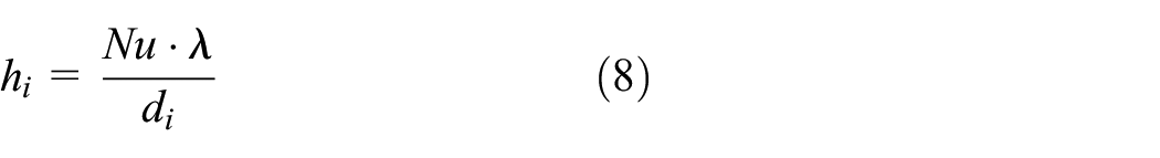
Here,
Finally, the heat transfer coefficient of condensation/evaporation is obtained as follows:
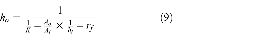
Here,
Uncertainty analysis
The uncertainty of direct measurement is shown in Table 2.
Summary of experimental uncertainties.

The uncertainty is analyzed using the “quadratic power method.” 28 Assuming a total variable, it is calculated using n independent variables.

Therefore, the uncertainty of X is determined by the uncertainty of each independent variable:

where
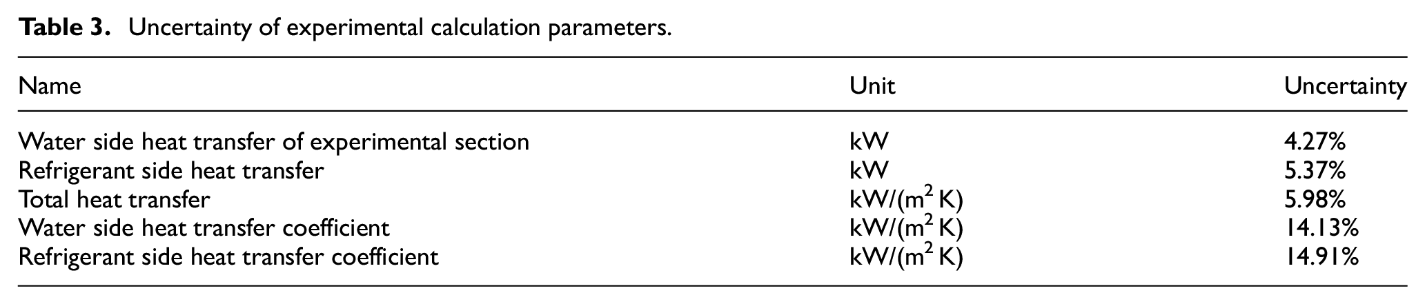
The uncertainty of different variables in this experiment can be calculated from the above formula, and Table 3 shows the uncertainty of the experimental calculation parameters.
Uncertainty of experimental calculation parameters.
Evaporation heat transfer
Experimental visual observation
It can be seen from Figure 3(a) and (b) that bubbles generated and separated from the surface of the enhanced tube are relatively rare under low heat flux, and the bubble diameter is small, so the gap between bubbles in the refrigerant liquid is large. In contrast, when the heat flux is high, there are a larger number of bubbles on the surface of the enhanced tube wall, and the diameter of the bubbles is much larger than that of the low heat flux; which makes it easier to observe. Through the visualization window, it can be observed that the density of the bubbles in the refrigerant liquid is higher, almost covering the whole visualization window, and the volume of the bubbles is larger. With heat flux density increases, the heat transfer increases gradually, the boiling heat transfer process becomes more intense, and more and more refrigerant is evaporated near the wall of the heat exchange tube. These bubbles fuse with each other into large bubbles, and quickly escape from the heat exchange tube wall, so there are more bubbles near the heat exchange tube at high heat flux density.
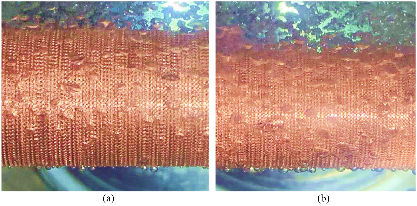
(a) Low density boiling diagram of refrigerant. (b) High density boiling diagram of refrigerant.
Total heat transfer coefficient
The heat transfer process includes the convective heat transfer of the cooling water in the tube, heat conduction through the copper tube wall, and evaporation heat transfer of the refrigerant outside the tube.
Figure 4 compares the total heat transfer coefficients of a smooth tube and two enhanced tubes at various inlet water temperatures. From the above figure, we can clearly establish that (1) when the test tube is a smooth tube, the total heat transfer coefficient increases with the increase in inlet water temperature; while the total heat transfer coefficient of the two enhanced tubes decreases with the increase in inlet water temperature. (2) In the range of inlet water temperature, the total heat transfer coefficient of tube #3 is slightly higher than that of tube #2.

Total heat transfer coefficient versus inlet water temperature at the saturated temperature of 7°C.
Figure 5 demonstrates the total heat transfer coefficient as a function of water flow rate at the same saturated temperature. The experiments indicate that (1) the heat transfer coefficient of all three tubes increase with the increase in water flow rate, but the increase in the total heat transfer coefficient of the two enhanced tubes tend to stabilize when the water flow rate reaches a certain degree. (2) In the range of the test water flow rate shown, the total heat transfer coefficient of tube #3 is greater than that of tube #2.
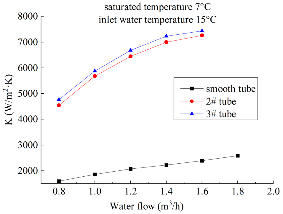
Total heat transfer coefficient versus water flow at the saturated temperature of 7°C.
Heat transfer coefficient of water side
Figure 6 illustrates the relationship between the water side heat transfer coefficient and inlet water temperature. The experimental results reveal that the water side heat transfer coefficient of the smooth tube and that of the enhanced tubes increase with the increase in inlet water temperature. This is because the water side heat transfer coefficient is mainly determined by the water flow rate, but also has a certain correlation with its own physical properties. Therefore, when the water flow rate is constant, the increase in inlet water temperature leads to the decrease in water viscosity, which eventually increases the heat transfer coefficient. However, the increase of the water side heat transfer coefficient is not large, so the inlet water temperature is not the main factor affecting the water side heat transfer coefficient.

Heat transfer coefficient of water side versus inlet water temperature at the saturated temperature of 7°C.
Figure 7 shows the relationship between the water side heat transfer coefficient and water flow rate. The experimental results show that the water side heat transfer coefficient of the smooth tube and the enhanced tubes increases with an increase in water flow rate. As the water flow rate increases, some of the fluid near the wall rotates along the spiral surface, and a part of the fluid flows along the axial direction on the wall surface, which causes a periodic disturbance when passing through the convex spiral groove, thus enhancing the heat transfer. From the analysis of the rib tube structure, compared with the inner tube structure, the trapezoidal thread of the tube #2 is more conductive to the flow and disturbance of heating water and increase the heat transfer area. Therefore, the inner rib structure of tube #2 has a more obvious enhancement effect on the inner heat transfer coefficient of tube. When the water flow rate increases gradually, the variation of heat transfer coefficient on the water side is more obvious than that on the refrigerant side, because the water flow rate mainly increases the turbulence degree of water in the tube and enhances the disturbance effect. Therefore, the water flow rate has a greater impact on the heat transfer coefficient inside the tube.

Heat transfer coefficient of water side versus water flow at the saturated temperature of 7°C.
Heat transfer coefficient of refrigerant side
The refrigerant side heat transfer coefficient can be obtained from equation (9). The heat transfer coefficients of the two enhanced tubes increases. This is because there are straight ribs or grooves on the outer surfaces of the two enhanced tubes. This unique structure forms the optimized design of micropores, which not only increases the heat transfer area, but also provides the large number of vaporization cores required for evaporation heat transfer, and promotes the formation of high-efficiency liquid film evaporation in the process of liquid vaporization, which makes the liquid film of the bubble and tube wall thinner and reduces the number of tubes that can produce continuous bubbles under a small degree of superheat.
As shown in Figures 8 and 9 the heat transfer coefficient of tube #3 was higher than that of tube #2. This is because the two type of tubes are different. According to the analysis of heat transfer mechanism, tube #3 is grooved tube, which can facilitate the formation of vaporization core more easily. A large amount of vapor is discharged from the cavity, which disturbs the liquid on the surface of the pipe and enhances the convective heat transfer performance between the liquid and pipe. In the groove, the radius of the gas-liquid interface is larger, and the wall superheat required for nucleation is lower than that of the low-rib tube. For the surface-enhanced tube with a hole structure, vapor bubbles are generated in the groove during the boiling process to form an activation hole. The liquid in the activation hole evaporates to form a vapor bubble. With an increase in the steam pressure, the vapor bubble escapes from the groove, forming a low pressure in the hole. More liquid is inhaled into the activation hole, and a layer of liquid film is formed on the inner wall of the hole. Because the liquid film is thin and the thermal resistance is low, it can quickly evaporate and produce a large amount of steam, thereby increasing the heat transfer efficiency and enhancing the boiling. Therefore, the outer groove structure of the tube #3 is more conducive to the generation of bubbles and has a better effect on the enhancement of the heat transfer coefficient outside the tube.
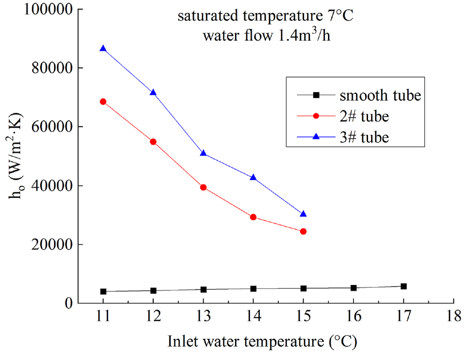
Heat transfer coefficient of outside versus inlet water temperature at the saturated temperature of 7°C.

Heat transfer coefficient of outside versus water flow at the saturated temperature of 7°C.
The refrigerant side heat transfer coefficient of the two enhanced tubes decrease with an increase in the inlet water temperature. Theoretically, it is expected that the heat transfer temperature difference will increase as the inlet waterside temperature increases, heat transfer is enhanced, and refrigerant boiling on the refrigerant side increases, similar to the heat transfer coefficient. However, the experimental trend is the opposite. This may be attributed to the fact that with the increase in inlet water temperature, the superheat of the wall increases further from the peak point. At this time, the bubbles converge and cover the heating surface, and the vapor removal process accelerates because of the direct interaction of bubbles, which causes the heat transfer coefficient of the outside to decrease. When the inlet water temperature rises, the variation of heat transfer coefficient outside the tube is more obvious than that inside the tube. This is because when the inlet temperature of water side rises, the temperature difference between water temperature and tube wall surface gradually increases, and the heat transfer is strengthened. The boiling heat transfer of refrigerant liquid is intensified, the total heat transfer is increased, and the bubble formation rate of tube wall is accelerated. Therefore, the inlet water temperature is the main factor of the change of refrigerant side heat transfer coefficient.
With the increase in water flow, the refrigerant side heat transfer coefficient of the two enhanced tubes first increase and then decrease. This is because, theoretically, with the increase in water flow, the wall superheat increases, number of activated holes increase, bubble motion intensifies, and boiling heat transfer is further enhanced. However, with a further increase in water flow, the bubbles cannot be discharged out of the hole in time, leading to the formation of a gas film. With the continuous increase in film temperature, burning points appear on the wall of the hole, which increases the thermal resistance, resulting in a decrease of heat transfer coefficient outside the tube instead of a rise.
Thermal resistance analysis
From the experimental results, the heat transfer area resistance of the water side, heat conduction resistance of the tube wall, boiling area thermal resistance of the refrigerant side, and total heat transfer area based on the external surface of the tube can be further calculated. The distribution of thermal resistance is evident, which is beneficial for further analysis of heat transfer enhancement. As shown in Figures 7 and 9, the water-side thermal resistance is higher than the refrigerant side thermal resistance. Therefore, the water-side thermal resistance is the focus of strengthening research; thus, it is meaningful to further study the single-phase heat transfer enhancement of this type of tube.
Condensation heat transfer
Experimental visual observation
By comparing Figure 10(a) and (b), under low heat flux, the column of condensate droplet is relatively rare and thin, and the condensate accumulates before dropping, condensing into liquid beads and dropping again, indicating that the refrigerant condensation amount is insufficient to make the condensate continuously drop. However, in the case of high heat flux, there is basically no column breaking phenomenon in the dropping process of refrigerant condensation liquid, and the condensation liquid continues to drop, and the liquid column is more dense. Form the theory of heat transfer, the condensation mode of refrigerant outside the tube is bead condensation, and the bead condensation is not completely wet the wall surface. Therefore, the refrigerant steam can directly exchange heat with the wall surface. The external condensing heat transfer at high heat flux is membrane condensation, it is characterized by the condensation completely wetting the wall. At this time, the latent heat released by refrigerant condensation can only be transferred to the wall of the heat exchange tube through the liquid film.
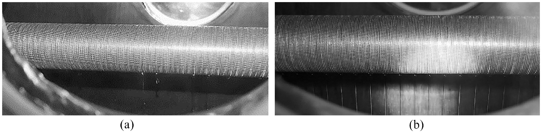
(a) Low density condensation diagram of refrigerant. (b) High density condensation diagram of refrigerant.
Total heat transfer coefficient
Figure 11 shows that when the water flow rate is constant, the total heat transfer coefficient of smooth tube increases with the increase of inlet water temperature, while the total heat transfer coefficient of the two enhanced tubes decrease. The total heat transfer coefficient of tube #2 is greater than that of tube #3.

Total heat transfer coefficient versus inlet water temperature at the saturated temperature of 35°C.
Figure 12 shows that with the continuous increase of the water flow rate in the tube, the internal disturbance and energy exchange of the fluid in the tube are constantly strengthened, and heat exchange inside and outside the tube has been strengthened. Therefore, the total heat transfer coefficient of smooth and enhanced tubes increases with the increase of water flow rate. In the range of test water flow rate, the total heat transfer coefficient of tube #2 is greater than that of tube #3.
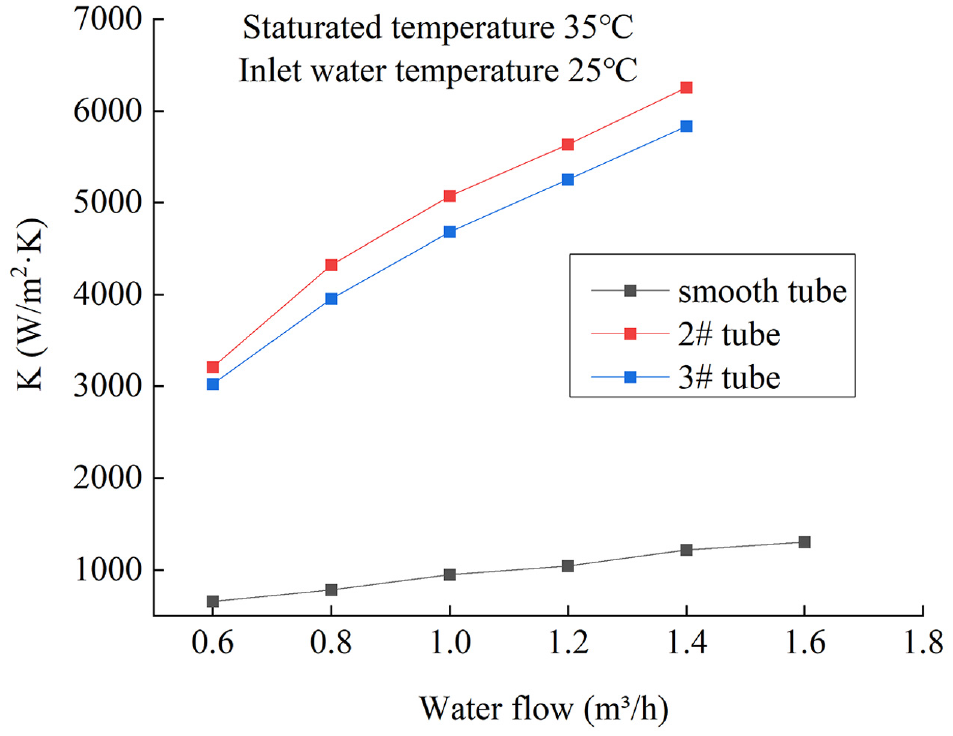
Total heat transfer coefficient versus water flow at the saturated temperature of 35°C.
Heat transfer coefficient of water side
Figure 13 indicates that the water side heat transfer coefficient of the smooth tube and enhanced tubes increase slowly with the increase in inlet temperature. That is because the Reynolds number is mainly determined by the flow rate of the fluid, equivalent diameter of the pipeline, and kinematic viscosity of the fluid. When the water flow rate and the equivalent diameter of the tube are kept constant, the kinematic viscosity of the water decreases with the increase of the inlet temperature, and the Reynolds number increases. Reynolds number is the main factor affecting the heat transfer coefficient on the water side, and it can be seen from equations (6) and (8) that as the Reynolds number rises, the heat transfer coefficient of the water side increases. Therefore, the heat transfer coefficient of the water side increases with the increase of inlet temperature. However, the increase of water side heat transfer coefficient is not large, so the inlet water temperature is not the main influence of water side heat transfer coefficient.

Heat transfer coefficient of inside versus inlet water temperature at the saturated temperature of 35°C.
When the inlet water temperature is constant, the water side heat transfer coefficient increases with the increase in water flow rate, as shown in Figure 14. This is because, with the increase in water flow, the water flow velocity in the pipe also increases, disturbance is enhanced, water-side boundary layer is destroyed, water-side thermal resistance is reduced, and heat transfer coefficient is increased. The heat transfer coefficient of tube #3 is higher than that of tube #2. Tube #3 has a triangular internal thread, whereas tube #2 has a trapezoidal internal thread; therefore, the shape of the internal thread of the tube has a significant influence on the water-side heat transfer coefficient.

Heat transfer coefficient of water side versus water flow at the saturated temperature of 35°C.
Heat transfer coefficient of refrigerant side
As can be seen from the Figures 15 and 16, the heat transfer coefficient of tube #2 is higher than that of tube #3. From the analysis of the rib structure, the low rib tube has a stronger drainage capacity, while the groove tube has a relatively weak drainage capacity, which leads to the accumulation of a large amount of liquid in the groove and the formation of liquid film, which increases the heat transfer resistance and hinders the condensation heat transfer.
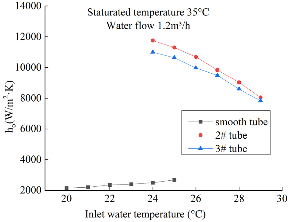
Heat transfer coefficient of outside versus inlet water temperature at the saturated temperature of 35°C.

Heat transfer coefficient of outside versus water flow at the saturated temperature of 35°C.
When the water flow is constant, the heat transfer coefficient on the refrigerant side of the two enhanced tubes decreases with the increase of inlet water temperature. At this time, with the continuous rise of inlet water temperature, the subcooling degree of the condensation on the refrigerant side decreases, resulting in the decrease of heat flux and heat transfer coefficient. In addition, due to the strong drainage capacity of the enhanced tube, the condensate volume changes with the change of inlet temperature. But because of its better drainage performance, the thickness of liquid film has little change. At this time, the inlet water temperature increases and the heat transfer coefficient decreases, which may be caused by the decrease of heat transfer temperature difference and heat flow density. Compared with the heat transfer coefficient inside the tube, the variation range of the heat transfer coefficient outside the tube is more obvious. The increase of inlet water temperature accelerates the rate of refrigerant condensation. Therefore, the inlet water temperature has a greater impact on the condensation heat transfer outside the tube.
When the inlet water temperature is constant, the refrigerant side heat transfer coefficient increases with the increase of water flow rate, but its increasing trend gradually decreases with the increase of water flow rate. When the water flow rate is small, the drainage capacity of the enhanced tube is better and the change of liquid film thickness is small. In this case, the heat flow density is the dominant factor, so the condensation heat transfer coefficient changes obviously with the increase of water flow rate. With the increase of water flow rate, the amount of condensing liquid is too large and the draining capacity of enhanced tube is insufficient, and the liquid film gradually thickens. At this time, heat flux and liquid film act simultaneously, so the upward trend becomes slow. In addition, it may be that as the water flow rate continues to rise, the enhanced tube gradually reaches its maximum heat transfer capacity. Therefore, the increase of water flow rate can not significantly improve the heat transfer capacity, but the increase of the flow makes the heat transfer coefficient outside the tube tend to be flat. With the increase of water flow rate, the variation of heat transfer coefficient inside the tube is more obvious than that outside the tube, so the influence of water flow rate on the heat transfer coefficient inside the tube is greater.
Conclusions
In this experiment, the condensation and evaporation heat transfer coefficient of R410A was experimentally studied outside the smooth tube and two bilateral enhanced tubes. By analyzing the variation trend of the water side and refrigerant side heat transfer coefficient and the total heat transfer coefficient of the heat exchange tube under different inlet water temperature and water flow rate, the trend analysis was carried out. Here are the main conclusions:
Condensation:
When the water flow rate remains unchanged, the kinematic viscosity of water decreases with the increase in the inlet temperature, so the water side heat transfer is enhanced. When the water inlet temperature is constant, with the increase in water flow rate, the water flow velocity in the tube also increases, disturbance is enhanced, water side boundary layer is destroyed, water side thermal resistance is reduced, and heat transfer coefficient inside the tube is increased. Compared with inlet water temperature, water flow rate has a greater effect on the heat transfer coefficient inside the tube.
When the water flow rate remains unchanged, with an increase in the inlet water temperature, the subcooling degree decreases, resulting in a decrease in the heat flux density and heat transfer coefficient inside the tube. With the change in water flow rate, in the later stage, the amount of condensate is significantly large, drainage capacity of the enhanced tube is insufficient, so the heat transfer coefficient outside the tube tends to be flat. From the analysis of the rib structure, the low rib tube has a stronger drainage capacity, so the heat transfer coefficient outside the tube #2 is greater than that of tube #3. Compared with water flow rate, inlet water temperature has a greater effect on the heat transfer coefficient outside the tube.
Evaporation:
When the water flow rate remains unchanged, with an increase in the inlet water temperature, the kinematic viscosity of water decreases and Reynolds number increases, so the heat transfer coefficient on the water side goes up. When the water inlet temperature is constant, with the increase in water flow rate, the degree of turbulence in the tube is enhance, and the disturbance in the tube is increased, so the heat transfer inside the tube is enhanced. Compared with inlet water temperature, water flow rate has a greater effect on the heat transfer coefficient inside the tube. From the analysis of the rib tube structure, the trapezoidal thread of the tube #2 is more conductive to the flow and disturbance of heating water and increase the heat transfer area. Therefore, the water side heat transfer coefficient of tube #2 is higher than that of tube #3.
When the water flow rate remains unchanged, with an increase in the inlet water temperature, the resulting bubbles accumulate and cover the heating surface, so the heat transfer coefficient outside the tube does not rise but falls. When the water inlet temperature is constant, with the increase in water flow rate, bubbles movement intensify, but it cannot be eliminated out of the hole in time, which increases the thermal resistance and deteriorates the heat transfer, so the heat transfer coefficient outside the tube rises first and then falls. From the analysis of the rib tube structure, compared with the low rib tube, the grooved tube is more conducive to the formation of vaporization core, so the heat transfer coefficient of tube #3 is large. Compared with water flow rate, inlet water temperature has a greater influence on the change of heat transfer coefficient outside the tube.
By analyzing the thermal resistance of the heat exchange tube, it is concluded that the thermal resistance of the outside the smooth tube is the main thermal resistance. The main thermal resistance of the enhanced tubes are transferred to the inside the tube, so it is of great significance to further study the single enhanced heat transfer of this kind of tube.
Footnotes
Handling Editor: Chenhui Liang
Declaration of conflicting interests
The author(s) declared no potential conflicts of interest with respect to the research, authorship, and/or publication of this article.
Funding
The author(s) disclosed receipt of the following financial support for the research, authorship, and/or publication of this article: The project was supported by the Key Laboratory of Multiphase Flow and Heat Transfer in Shanghai Power Engineering (No. 1N-15-301-101).