
Abstract
An elastoplastic contact model of two cylinders is proposed in this paper. The crossing angle of two cylinders axes is introduced into the contact model. An analytical solution including the tangential displacement and tangential load under the axis crossing angles is provided. The finite element method is used to verify analytical solutions. The verification result shows that the analytical solution is in good agreement with the simulation result obtained by the finite element analysis. The stress distribution law of the cylinder contact surface is analyzed based on the contact model. The influence of model parameters on tangential mechanical properties is explored. Results show that tangential mechanical properties of the cylinder are governed by many factors, such as the applied load, material properties, and axis crossing angle. Cylinder contact models with different axis crossing angles can be applied to some engineering structures, such as roller bearings and gear meshing.
Keywords
Introduction
Contact between two cylindrical models is often present in various engineering fields, such as gears, roller chains, and roller bearings. In such instances, extremely high contact pressures are often present. The contact stiffness is important for the precision of mechanical parts and asperities. Therefore, it is necessary to consider the influence of normal contact stiffness and tangential stiffness.
Since contact exists is widely present in engineering parts and surfaces, modeling plays an important role in understanding the friction and wear between contact surfaces. Various contact models can be found in the existing literature. Greenwood and Williamson 1 established one of the earliest models of elastic rough surface contact (the G-W model). Moreover, the authors were also the first to propose the plasticity index. Majumdar and Bhushan 2 proposed the M-B model based on the classification theory. The G-W model is based on statistical analysis and the M-B model is based on fractal theory. Even though both models show good agreement with the actual results, experimental repeatability is still a problem. Chang et al. 3 proposed a fully elastic and fully plastic contact model and applied it to the statistical contact model of rough surfaces. In addition, based on elasticity and plasticity, Kogut and Etsion 4 analyzed the deformation process in the elastoplastic stage based on finite element analysis (FEA). In addition, the authors provided some critical parameters, such as contact pressure and contact area. However, the research on the elastoplastic process is also limited to the finite element method (FEM), and no definite analytical solution is given. Consequently, no quantitative analysis is impossible.
When the tangential force is considered, many researchers have proposed static friction models.5,6 Bowden and Tabor 7 concluded that the initiation of sliding is the result of the combined action of tangential stress and normal stress. When the shear stress exceeds the shear strength, sliding will occur. Chang et al. 3 established that slippage is caused by the yield of a single point, that is, as long as the single point yields, the entire model will slip. The classic tangential contact model is the partial slip solution proposed by Mindlin. 8 However, it is only applicable to the elastic phase. Fujimoto et al. 9 modeled elastic and plastic tangential contact. However, elasticity and plasticity models were separately proposed. Therefore, the elastoplastic stage cannot be analyzed. Subsequently, Brizmer et al. 10 used the von Mises yield criterion and the fully viscous condition to simplify and improve the elastoplastic contact. Finite element (FE) and numerical fitting methods were combined to constitute their model. The research on the elastoplastic stage is limited to the FEM and no analytical formula is provided.
According to Wu et al., 11 angular misalignment of cylindrical rollers leads to an aggravation of the edge effect of the stress at roller ends. This, in turn, affects the bearing capacity and fatigue life of the bearing. Misalignment of cylindrical rollers involves the problem of the contact angle. Chen et al. 12 used the plane strain FEM to simulate the jaw joint for superelastic materials. For such problems, the angle becomes a factor that cannot be ignored. In previous studies, the contact model of the cylinder mainly focused on the contact between two parallel cylinders. As such, the elastoplasticity of the cylinder contact model under different axis angles was not analyzed. In our previous work, Guo et al. 13 investigated the contact model of two cylinders under different axis crossing angles. However, only normal contact characteristics of the contact model were explored, that is, the tangential direction was not investigated. Cattaneo 14 and Mindlin 8 pointed out that the contact area between two parallel cylinders is rectangular. A central stick area with two surrounding slips areas is generated after the tangential load is applied. Johnson 15 and Hamrock 16 both provided clear solutions in their papers for the elastic phase of cylinder contacts. Deformation of the cylinder in the elastoplastic stage is mostly based on the FE study. This is particularly true for some contact models between the cylinder and the plane.17–20 Due to relative complexity, analytic equations are rarely used to accurately describe this process. However, some researchers approximate this stage by interpolation. For example, Brake 21 used the cubic Hermite interpolation function when investigating the elastoplastic deformation stage. The authors concluded that the entire stage is smooth, continuous, and monotonous. Sharma and Jackson 22 and Jackson 23 used FEA based on various material properties and established an analytical solution for the plastic stage. Some conclusions in the cylinder study also apply to the spherical contact model. Hu et al. 24 proposed a new elastoplastic conformal contact model between cylinders. Furthermore, the authors provided an explicit solution for the normal force-displacement relationship of elastoplastic conformal contact. This solution can be applied to practical engineering problems with high load and high plasticity. Vijaywargiya and Green 25 explored the deformation, force, stress information, and energy of two parallel cylindrical contacts based on the FEM. FEA provides trends in deformation, reaction forces, stress, and net energy loss as a function of interference and sliding distance between cylinders. Pereira et al. 26 proposed an improved cylindrical and planar contact model that describes the contact force as an explicit function of penetration. Moreover, the authors verified the performance of the proposed model by analyzing a multi-body crank-slider mechanism with mechanical clearance in one of the joints. Shi et al. 27 established a macroscopic analysis model of tangential stiffness based on the fractal theory. In addition, the authors evaluated the effect of influencing factors on tangential stiffness. Numerical results show that the tangential stiffness of the asperity is determined by many factors. Sharma and Jackson 28 investigated the contact between an elastoplastic cylinder and a rigid plane. Based on FEA with symmetric boundary conditions, the cylinder modeling is divided into quarter circles. The FE results of elastic and fully plastic cylinders in contact are compared with the existing models. Vázquez et al. 29 explored the analytical solution of cylindrical contact with reverse slip. In the above-mentioned contact model, the axis crossing angle of the contact model is not considered. Most of the research on the elastoplastic stage is based on the FEA, and no definite analytical solution is provided.
Therefore, a cylindrical contact model with different axis crossing angles is proposed in this paper. The tangential load and the normal load are considered in the tangential contact process of the contact model. Analytical solutions of the normal and tangential forces and displacements of the contact model are determined by formula derivation and interpolation. Lastly, the results are verified by the FEA.
Theoretical background
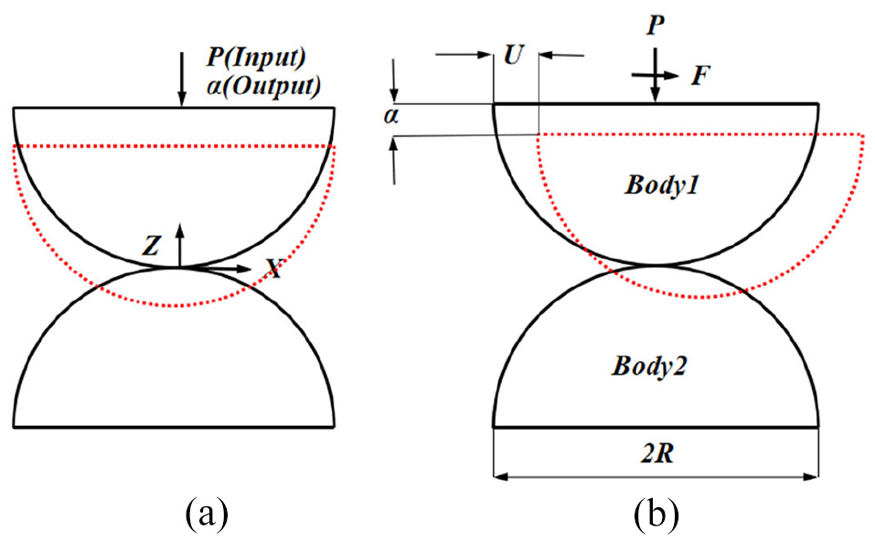
Mechanical parts and machined surfaces in contact are characterized by relatively complex Cases of gear contact or roller bearing contact can be simplified to a cylindrical contact. During machined surface contact, regular and periodic morphological features in the rough surface are separated from random morphological feature components. Moreover, regular morphological features determined in the rough surface are extracted. In addition, regular morphological features determined on the rough surface are equated into two regular cylindrical contacts with different axis crossing angles. Therefore, a cylindrical contact model with different axis crossing angles is established, as shown in Figure 1(a).

Cylinder contact sketch: (a) cylinder contact, (b) 90°, and (c) 0°.
Since the normal load and tangential load are simultaneously applied to the contact model, the parameters will be coupled at the contact surface. To simplify the analysis process, the following assumption is made for the contact model. Using the same material, the normal load does not produce displacement in the tangential direction, and the tangential load does not produce displacement in the normal direction. This significantly simplifies the analysis process. Hence, when only the normal load is present, the contact model will not slip regardless of the friction between the contact models.
Radius R of the investigated cylinder contact model is 2.5 mm. Since this is considered as macro-scale modeling and the material of the two cylinders is the same, the adhesion effect can be ignored. If the essence of friction is caused by the contact of microscopic bumps on the surface of the object, the normal load, tangential load, and friction force will be entangled. In the first-order approximation, complex problems can be sidelined and pure normal contact problem is firstly investigated. Frictionless contact and negligible attractive forces are assumed, that is, lack of adhesion force is presumed.
With different axis crossing angles, the contact surface will produce ellipses with different eccentricities. In particular, when the axis crossing angle of the two upper and lower cylinders is 90°, the shape of the contact surface is circular, as shown in Figure 1(b). When the axis crossing angle of the two upper and lower cylinders is 0°, the contact surface is rectangular, as shown in Figure 1(c).
A normal load P is applied to the upper cylinder with radius R, and the cylinder produces normal displacement

Schematic diagram of cylinder contact: (a) load input and displacement output and (b) cylinder size and displacement direction.
Cylinder normal contact model
Firstly, pure normal contact of cylinder contact model is investigated. When a normal load P is applied to the contact model of two cylinders, the contact model will generate a corresponding normal displacement

The contact model under the normal load: (a) without normal load and (b) with normal load.
Normal displacement of the cylinder contact surface at M1 is

For the initial gap h between any two points on the surface of the cylinder, the distance at which any two points on the contact surface converge to each other, L, can be expressed as:

The cylinder contact model is in the elastic phase for the normal load P is not sufficiently large. The critical force A from the elastic stage to the elastoplastic stage is given by equation (14). The general equation for the displacement of each point in the semi-infinite boundary plane under the action of distributed pressure during the elastic deformation stage of the cylindrical contact model can be expressed as 15 :

where

Distance
Schematic diagram of contact surface relationship.
By integrating equation (3) and combining equation (2) with equation (3), the relationship between the normal displacement
where
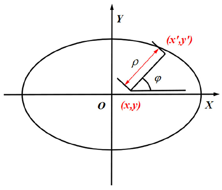
The eccentricity of the contact ellipse can be obtained according to equation (6),
13
where

With a gradual increase in the normal load, the contact model is transformed from the point contact to the surface contact. Then, the contact area of the model can be obtained by employing equations (2) and (3):

Normal contact deformation increases with the normal load P. Then, the cylinder contact model transitions from the elastic phase to the
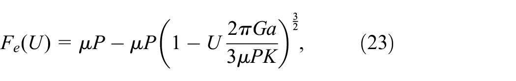
Critical mean contact pressure at which yielding of the contact model starts can be expressed as 30 :

where
The C-value can be expressed according to Green 30 :

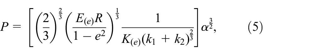
Combining equations (5) and (7) results in:

By combining equations (8) and (10), a critical total load

By combining equations (5) and (11), critical normal contact deformation from the elastic phase to the elastoplastic phase,
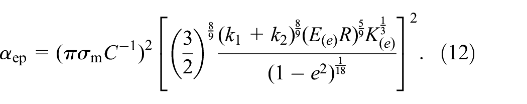
By substituting equation (12) into equation (10), the critical contact area from the elastic phase to the elastoplastic phase,

Substitution of equation (12) into equation (11) yields the critical contact load

Based on the equations (12), (13), and (14), eccentricity e and contact model shape parameter R are related to critical parameters. Different contact angles and contact model shapes affect the critical parameters. Four different angles of the cylinder contact model are mainly investigated in this paper: 15°, 45°, 60°, and 90°.
As the normal load continues to increase, the cylindrical contact model exceeds the initial yield point
Deformation of the contact model in the elastoplastic phase is mostly investigated via numerical investigations. This is particularly true for some cylindrical and planar contact models. Due to the relative complexity of the process, sphere-to-plane contact models are rarely used to accurately describe the elastoplastic phase via analytical expressions. Kougt and Etsion 4 established the deformation process in the elastoplastic phase for the sphere-to-plane contact based on the FE approach. However, some researchers have approximately described this phase by interpolation. For example, Brake 21 used three Hermite interpolation functions when investigating the elastoplastic deformation phase. The authors concluded that the deformation phase is smooth, continuous, and monotonic.
The normal displacement continues to increase with the normal load P. Then, the contact model enters the plastic phase. According to the indentation tests,
32
when the contact model enters the plastic phase, the critical average pressure

According to the Abbott theory, 31 when the contact model enters the plastic phase, the contact area becomes twice as large compared with the contact area in the elastic phase. According to equation (10), the contact area in the plastic phase can be obtained as:

Therefore, the relationship between the normal load P and normal displacement

According to the Tabor theory, 32 critical normal load between the elastic and the plastic phases of the contact model can be expressed as:

Based on equations (17) and (18), critical normal displacement from the elastoplastic phase to the plastic phase can be obtained as:

Cylinder tangential contact model
In Section 3, the pure normal contact model of the cylinder is explored. Based on the normal contact model, the combined normal and tangential contact problems of the contact model are investigated. After the normal load P is applied, the elliptical shape of the contact surface is obtained, and the cylinder produces a normal displacement
The contact state of the loaded cylinder: (a) subjected to the normal load and (b) subjected to the normal load and the tangential load.
When the contact model is in the elastic stage and only the normal load is applied, the contact surface displacement of the two cylinders can be expressed as 15 :

where G is the equivalent shear modulus of the cylinder,
Therefore, the aforementioned model is not applicable when sliding occurs. Hence, it is necessary to seek a new form of tangential stress distribution that accounts for sliding. Then, a combination of known tangential stress distribution equations can be used to construct the tangential stress distribution. By superimposing two Hertzian stresses, a new tangential stress distribution that satisfies boundary conditions can be obtained as follows:

where c is the major axis of the contact small ellipse and d is the minor axis of the contact small ellipse, a is the major axis of the contact small ellipse, and b is the major axis of the contact small ellipse.
Identical top and bottom cylinders are used during the tangential contact process. To produce constant tangential displacement, the tangential load F is applied to one of the cylinder models. Then, according to the interaction force, the tangential displacement produced by the other cylinder model is −U. The two cylinders can be kept in balance, with the relative displacement produced between the two cylinders being 2U. Therefore, for the shear stress distribution according to equation (21), a specific derivation process is obtained from. 33 The tangential displacement of the cylinder in the elastic phase can be expressed as:

where
The tangential contact stiffness is equal to

When the cylindrical contact model subjected to the normal load reaches the plastic stage, the tangential load


Equation (26) is derived to obtain the tangential stiffness in the plastic phase

When the contact model subjected to the normal load reaches the elastoplastic stage, both elastic and plastic deformation occurs. This process is relatively complicated. Therefore, obtaining the analytical solution to accurately describe this process is relatively complex. This process can be approximately described by the interpolation method. 18
The tangential displacement is expressed according to equation (23) in the elastic stage, while the tangential displacement is expressed according to equation (26) in the plastic stage. Therefore, the relationship between the tangential load and the tangential displacement in the elastoplastic stage is obtained by interpolation. The radius R of the two cylinders is 2.5 mm, the elastic modulus is 210 MPa, the yield strength is 350 MPa, the friction factor is 0.2, the Poisson’s ratio is 0.3, and the axis crossing angle is 60°. These parameters are used for interpolation.
Cubic spline interpolation is used. In addition to satisfying discrete data points in the interpolation function, it is also necessary to satisfy the existence and continuity of the first and second derivatives at several discrete data points. Here, it is assumed that the tangential displacement of the contact model at the initial yield point is U1, and that the tangential displacement of the critical point in the elastoplastic to plastic phase is U2.
Cubic spline interpolation can be expressed as:
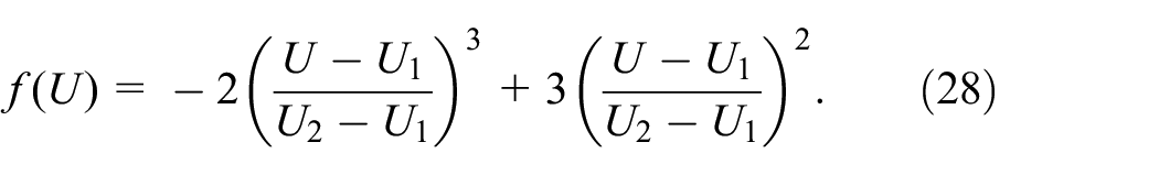
The interpolation expression in the elastoplastic phase is established according to the derived tangential displacement expression in the elastic phase and tangential displacement expression in the plastic phase:

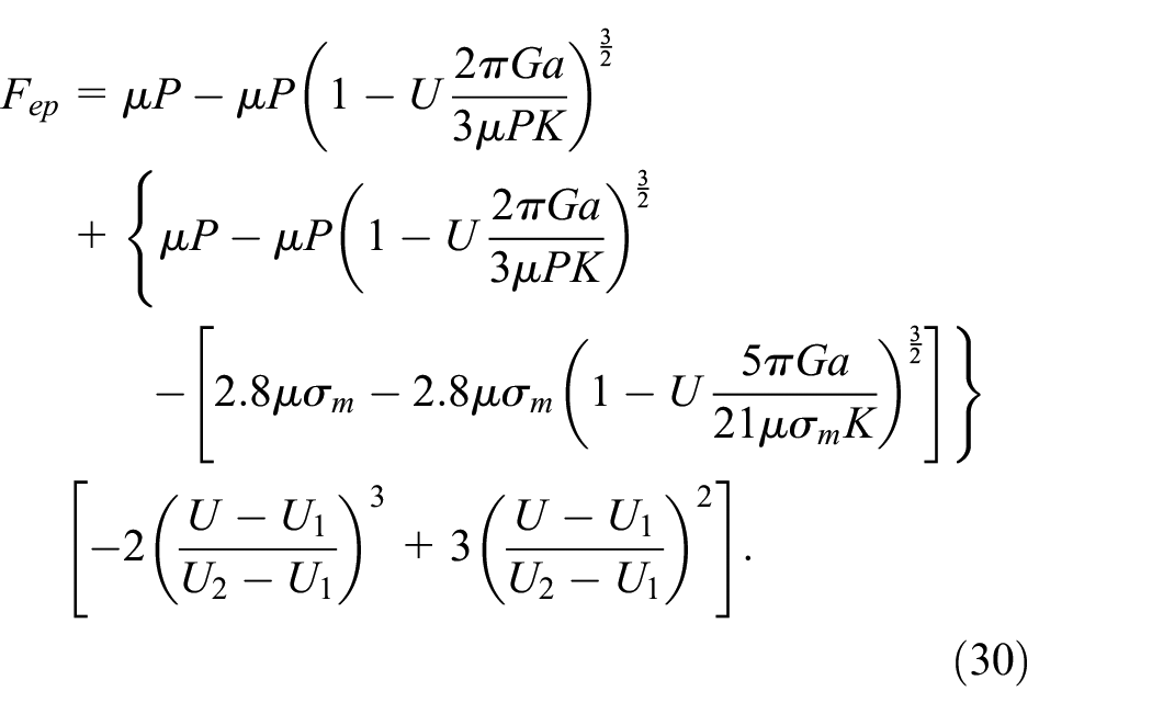
To ensure the continuity and smoothness of the contact process, the following relationship should be maintained between the tangential load F and the tangential displacement U at the critical point in the elastic phase, elastoplastic phase, and plastic phase:

The relationship between tangential load and tangential displacement of the cylindrical contact model obtained via cubic spline interpolation during the entire deformation stage is shown in Figure 6. The tangential load and tangential displacement are monotonous, continuous, and smooth during the elastic, elastoplastic, and plastic phases.

Cubic spline interpolation.
Finite element model
A cylindrical contact model for different axis crossing angles is established in this paper. Moreover, the effect of normal and tangential loads on the contact model is considered. A numerical simulation program ABAQUS is used for the FEA. To improve computational costs, a half circle is used to create a cylinder. The upper and lower cylinders contact models are characterized by the same shape and size, and the radius R is 2.5 mm. As shown in Figure 7, a model with different axis crossing angles of 15º, 45º, 60º, and 90° was established. The influence of different axis crossing angles on contact mechanics characteristics is then investigated.

Contact models with different axis crossing angles: (a) 15°, (b) 45°, (c) 60°, and (d) 90°.
The main FEA steps for the cylindrical model are as follows. First, material properties are created and ABAQUS is used to assign material properties to the cylindrical model. Model properties, including density, elasticity, and plasticity, are created and edited through the property module. Finally, material and model properties are respectively assigned to the cylindrical model. Specific material parameters are shown in Table 1.
Material properties of the model.

Plasticity is a material property that produces permanent material deformation under a given load. For most engineering materials, when the stress is lower than the proportional limit, the stress-strain relationship is linear. Most materials exhibit elastic behavior when the stress is lower than the yield point.
Metal engineering stress is called the nominal stress, and its corresponding strain is called the nominal strain. The data obtained in uniaxial tension and compression experiments are usually given in terms of nominal stress and nominal strain. In ABAQUS, true stress and strain values can be used to define plasticity. However, most test data are often provided as nominal stress and strains. Hence, the nominal stresses and strains must be converted to true values according to certain equations.
The true stress and true strain values are shown in Table 2:
True stress and true strain.

The lower cylinder model is fixed in its lower plane, that is, six degrees of freedom for the nodes in the bottom cylinder lower plane model are fixed. Nodes in the upper plane of the upper cylinder model allow normal and tangential degrees of freedom, while the remaining four degrees of freedom are fixed. Boundary conditions of the contact model are shown in Figure 8. The load is applied using concentrated force. The concentrated force method in the load module is chosen, and the normal load P, as well as the tangential load F, are applied to the previously described coupling point.

Schematic diagram of the contact model restraint and load action: (a) 15°, (b) 45°, (c) 60°, and (d) 90°.
The employed finite elements are designated in ABAQUS as C3D8I. The number of elements is 173,520 with the corresponding number of nodes being 173,118. The mesh between the contact parts is shown in Figure 9.

Local mesh refinement: (a) overall mesh, (b) contact site mesh and (c) contact site mesh enlargement.
Stress-strain analysis
Stress on the contact surface of the cylindrical contact model is investigated on the 60° cylindrical contact model. Moreover, the shape of the contact area under different axis crossing angles is displayed.
According to Figure 10, when the contact model is only subjected to the normal load, the von Mises stress distribution at the surface of two cylinders is relatively similar. As the normal load increases, the maximum contact stress appears below the contact surface, which means that the yield will first occur below the contact surface. As shown in Figure 11, when the tangential load is applied to the contact model, slippage occurs between the cylinders. The von Mises stress distribution between the two cylinders becomes asymmetric. This change is shown in Figure 12 from another perspective.
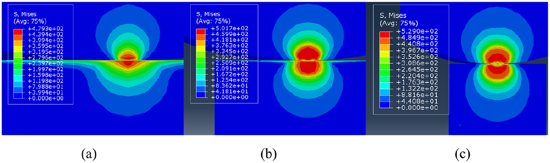
Von Mises stress distribution cloud diagram for the contact model subjected to the normal load: (a) P = 1 kN, (b) P = 15 kN, and (c) P = 30 kN.

Von Mises stress profile cloud diagram for the contact model subjected to tangential load: (a) F = 3.1 kN, (b) F = 3.5 kN, and (c) F = 3.9 kN (P = 20 kN).

Von Mises stress top-view cloud diagram for the contact model subjected to tangential load: (a) F = 3.1 kN, (b) F = 3.5 kN, and (c) F = 3.9 kN (P = 20 kN).
The plastic strain cloud diagram for the two contact models under different tangential loads is shown in Figure 13. With an increase in the tangential load, the plastic strain of the contact surface increases. Furthermore, the plastic area is continuously increasing and expanding to the central area. The tangential displacement increases with tangential load, as shown in Figure 14.

Cloud diagram of the plastic strain for the contact model subjected to the tangential load: (a) F = 3.1 kN; (b) F = 3.5 kN, and (c) F = 3.9 kN (P = 20 kN).

Tangential displacement cloud diagram under different tangential loads: (a) F = 3.1 kN, (b) F = 3.5 kN, and (c) F = 3.9 kN (P = 20 kN).
The shape of the cylinder contact surface model under different axis crossing angles is shown in Figure 15. When the axis crossing angle is 45° or 60°, the shape of the contact surface is an ellipse. When the axis intersection angle is 90°, the shape of the contact surface is circular, as shown in Figure 15(c). For the circular contact surface, the eccentricity is 0.

Deformation cloud map of the contact area under different axis crossing angles: (a) 45°, (b) 60°, and (c) 90° (P = 20 kN).
Verification of the finite element simulation
Analytical solution for the tangential displacement of the cylindrical contact model during the entire deformation stage is simulated via the FEM, and the results are verified. To ensure that the contact model does not slip, the tangential load should satisfy

Comparison of analytically obtained tangential displacements and FEA value: (a) 15°, (b) 45°, (c) 60°, and(d) 90° (P = 20 kN).
According to Figure 16, good agreement is observed between analytical and FEA results. Regardless of the stage (elastic, elastoplastic, or plastic), the tangential load will increase the tangential displacement. Moreover, when other parameters are fixed, the tangential displacement will increase with the axis crossing angle. This is because a higher crossing angle decreases the stiffness, which consequently increases the tangential displacement.
In Table 3, a comparison between the analytical solution of the tangential displacement and the FEA values is shown. According to the obtained results shown in Table 3, the maximum error between the tangential displacement analytical solution and the FE result is 11.3%, and the minimum error is 0.89%. When the remaining parameters are kept the same, the tangential displacement tends to increase with the axis crossing angle.
Comparison of analytical solution for the tangential displacement and the FEA values.

Numerical results and analysis
Verification carried out in the previous section confirms that equations (23) and (26) are accurate. In this section, the effect of the contact model parameters is investigated. Moreover, similarities and differences between the elastic and plastic stages are compared. Lastly, the influence of friction coefficient, radius, and axis crossing angle on contact area, tangential stiffness, and tangential displacement is explored.
According to Figure 17, the friction coefficient affects the contact area, tangential stiffness, and tangential displacement in the elastic stage. As the coefficient of friction increases, the contact area increases, an increase in speed is slowly decreasing, and the relationship between the two is nonlinear. Moreover, the tangential stiffness increases, the relationship between the two is nonlinear. Lastly, the tangential displacement decreases. This is because the frictional resistance is relatively large, which hinders the tangential displacement. Moreover, the contact area and contact stiffness have a decreasing trend with an increase in the axis crossing angle. However, the tangential displacement will increase with the contact angle.

The influence of friction coefficient in the elastic stage on the contact model: (a) contact area, (b) tangential displacement, and (c) tangential stiffness.
Based on the results shown in Figure 18, the cylinder radius affects the contact area, contact stiffness, and tangential displacement. As the radius of the cylinder increases, the corresponding contact area and tangential stiffness also increase. The tangential displacement decreases with the cylinder radius. Simultaneously, the relationship between the cylinder radius and the contact area, as well as the contact stiffness and tangential displacement is not linear. According to the equation proposed in the elastic phase, they are all in an exponential relationship.

The influence of radius of the elastic stage on the contact model: (a) contact area, (b) tangential displacement, and (c) tangential stiffness.
According to Figure 19, an increase in the friction factor will cause an increase in the contact area and tangential stiffness. Simultaneously, an increase in the friction coefficient will cause a decrease in the tangential displacement, which is the same as the influence trend of the elastic phase. Increasing the axis crossing angle will cause a decrease in the contact area and the contact stiffness, as well as an increase in tangential displacement. The friction coefficient and the axis crossing angle in the elastic stage as well as the plastic stage have the same influence on the contact model. This also shows that the contact model is smooth and continuous during the deformation process, which is consistent with the previously conducted theoretical analysis.
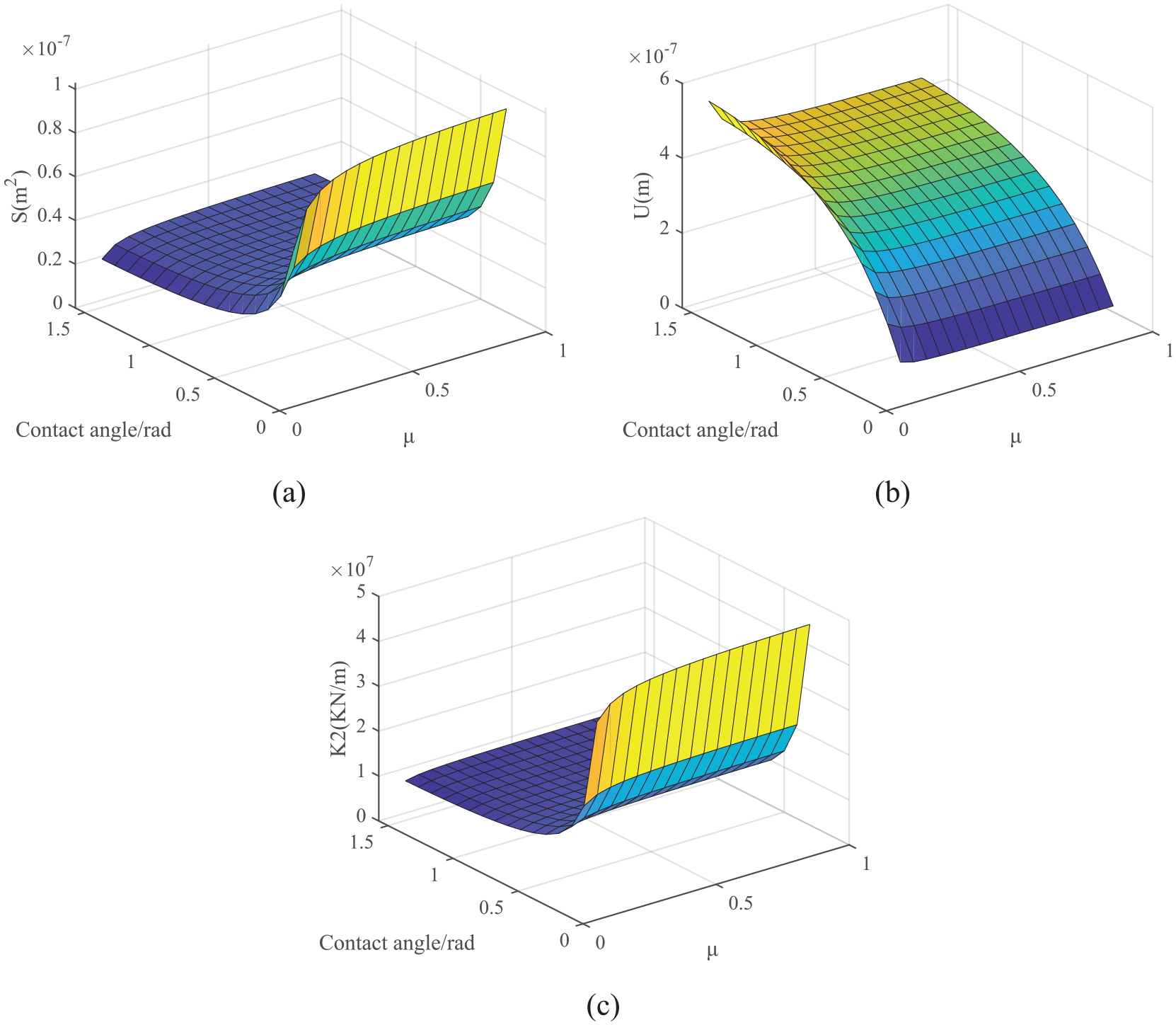
The influence of the friction coefficient in the plastic phase on the contact model: (a) contact area, (b) tangential displacement, and (c) tangential stiffness.
Based on the result shown in Figure 20, the cylinder radius affects the contact area, tangential stiffness, and tangential displacement in the plastic phase. When the cylinder radius increases, the contact area, and contact stiffness both tend to increase, while the tangential displacement tends to decrease. As the axis crossing angle increases, the contact area and contact stiffness tend to decrease, while the tangential displacement tends to increase. According to the comparative analysis with the elastic phase, it can be observed that the influence trend of the plastic phase on the contact model is consistent with the trend of the elastic contact. The aforementioned demonstrates that the contact model is smooth and continuous during the deformation process.

The influence of the plastic stage radius on the contact model: (a) contact area, (b) tangential displacement, and (c) tangential stiffness.
Conclusions
In a mechanical structure, some mechanical parts and kinematic pairs are characterized by contact problems. Moreover, different angles cause various contact problems. In this paper, a regular cylindrical contact model with different axis crossing angles is proposed. According to the continuity of the contact model during the deformation process, a series of critical interference values for the cylindrical contact model is obtained via formula derivation and data interpolation. Mathematical expressions of force and displacement in normal and tangential directions of the contact model are also provided. In particular, the tangential displacement expression in the elastoplastic stage of the contact model is obtained by the interpolation method. Verification based on the finite element analysis (FEA) is consistent with theoretical analysis. Based on this, the influence of friction coefficient, radius, and axis crossing angle on the contact model is explored. The cylindrical contact model has a nonlinear relationship between the tangential load F and the tangential displacement U. The influence of the axis crossing angle, friction factor, and radius on the mechanical properties is investigated. According to the comparative analysis of the elastic phase and the plastic phase, it can be found that the cylinder radius, friction coefficient, and axis crossing angle have the same influence on the mechanical characteristics of the contact model. This shows that the contact model is smooth and continuous during the deformation process. In future work, the contact model of the oscillatory tangential load will be investigated and experimentally validated.
Footnotes
Handling Editor: Chenhui Liang
Declaration of conflicting interests
The author(s) declared no potential conflicts of interest with respect to the research, authorship, and/or publication of this article.
Funding
The author(s) disclosed receipt of the following financial support for the research, authorship, and/or publication of this article: This work was supported by the National Natural Science Foundation of China, Natural Science Foundation of Beijing Municipality (grant number 51875009, 3162005).