
Abstract
The excitation technology of ultrasonic standing wave field is the core key to realize ultrasonic separation. This paper analyzes the excitation technology of (1, 1) mode ultrasonic separation of high-throughput ultrasonic micro-separator. There are two main problems: the coexistence of multiple modes in the separation cavity and the insufficient acoustic radiation force. In order to solve these two problems, this paper uses integrated circuit micromachining technology to process the ultrasonic micro-separator. The depth dimension of the cavity reaches 200 ± 0.5 µm, and the verticality of the side wall of the cavity reaches 83.36°. The degree of SFPD (Site Focal Plane Deviation) is less than or equal to 0.25 µm. Besides, this paper proposes an excitation method of saw-tooth frequency sweep of two anti-phase acoustic drivers. Finally, the experiments of the separator processed by the processing method proposed in this paper shows that, the excitation method proposed in this paper can effectively excite the (1, 1) mode, and shortens the time for the pattern formation of particle convergence, which greatly improves the separation efficiency. The separation throughput (flow rate) in one single cavity in this work can reach to 100 µl/min. It provides an effective basis for ultrasonic micro-separation technology.
Introduction
Microfluidic ultrasound separation has been increasingly used in biomedical applications and has been successfully used for the separation of exotics and carbon tetrachloride from body fluids. 1 Acoustofluidic separation has important real-world implications in many biological targets because it is highly scalable, capable of manipulating bioparticles ranging in size from tens of nanometers to several hundred micrometers and it has high exosome integrity, unbiased isolation, no requirement of additional reagent and washing steps. 2 Ultrasonic separation is highly scalability, capable of manipulating biological particles from tens of nm to hundreds of microns, and has high outer small body integrity, unbiased separation, without additional reagents and washing steps. Ultrasonic devices are small and compatible with chip manufacturing processes, providing the possibility for the integration of ultrasonic separator, with a wide range of applications in the medical, chemical, and biological fields. 3 With that being said, downsides such as low throughput and dependence on external equipment still impede successful commercialization from laboratory-based prototypes. 4
The studies on ultrasonic separation so far there are mainly two technologies of bulk acoustic wave (BAWs)5–7 and surface acoustic wave (SAWs).8,9 Both have been widely used to manipulate micro objects in the field of microfluidics. BAWs have been applied to microfluidic separations with many benefits, such as flexible placement of transducer, simple, and versatile setups. The research on excitation technology of Ultrasonic separation in this article is based on BAWs. Bulk acoustic waves (BAWs) are standing waves that propagate inside the resonant chamber of the microchannel. The transducer attached to the wall of the channel generates acoustic waves, which are supposed to propagate from the outside of the channel to form a standing wave. In order to form a stable ultrasonic standing wave field, the channel walls must be smooth and flat enough to act as a near-perfect reflector for sound waves. For the BAW-based devices, the microfluidic channel is typically made of materials with high acoustic impedances, such as silicon, glass, or stainless steel. Because of the significant impedance mismatch between the channel material and the fluid medium, the channel walls serve as nearly perfect reflectors for acoustic waves.2,10 Undoubtedly, machining quality of the channels is required high standard. Besides, the width of such a channel is typically a half-wavelength at the excitation frequency, which means that there is a standing-wave with one pressure node in the middle of the channel. For micrometersized particles the excitation is typically in the MHz range and the channel width and height of such devices are both in the order of hundreds of micrometers.5,11–13 This presents a great challenge to the processing of the separator.
Current acoustofluidic separation techniques do not have the throughput needed for apheresis. Currently, the throughput (flow rate) for acoustofluidic separation is 4 µl/min. In order for acoustofluidics to find more clinical relevance, it is important to improve throughput and precision. 2 Dubay et al. 14 reported an acoustic separator utilizing multiple channels to achieve high throughput, entirely made of polystyrene, fabricated by precision five-axis machining, with an average channel width of 544 ± 6.4 µm, the throughput of single channel for acoustofluidic separation is about 80 µl/min. Hill from Southampton University in the United Kingdom fabricated an ultrasonic separator based on the principle of one-dimensional standing waves, made of silicon and glass. The depth of the separator using a double-sided alignment process and standard wet KOH etching is 250 ± 40 µm. 15 For the channel made of silicon material, no reports of other fabrication methods have been seen, and the effect of channel quality on ultrasonic separation has not been studied in detail, to our knowledge.
In this work, the effect of channel quality on ultrasonic separation is studied, and the separator processing method based on integrated circuit micro-nano fabrication technology is introduced in detail. The depth dimension of the cavity reaches 200 ± 0.5 µm, and the verticality of the side wall of the cavity reaches 83.36°. The degree of SFPD is less than or equal to 0.25 µm. The separators fabricated in this paper are tested by experiments, which can effectively improve the separation efficiency. Currently, throughput (flow rate) of the acoustofluidic separation is 4 µl/min. 2 The separation throughput (flow rate) in one single cavity in this work can reach to 100 µl/min. 16 This work suggests that if the principle of integrated circuits is further used, multiple separators can be connected in parallel, so that, it is possible to achieve an order of magnitude increase in throughput.
On micrometer scale, the majority of the acoustic methods use a constant frequency to manipulate particles, 10 only a small number of studies have investigated the effect of frequency on the manipulation of the particles. They manipulate particles of different sizes to distribute in different positions (large particles 10 microns, small particles 5 microns) by switching the frequency of the first and third resonant modes of the fluid channel.17–19 Sweeping frequency can effectively improve the acoustic radiation force, and almost all the application of frequency-sweep are on centimeter scale.20,21 Particle manipulation in one or two dimensions is also possible by employing phase differences. 22 However, the combination of phase difference and frequency sweep to excite the micron-scale separators has not been reported yet, to our knowledge.
This paper proposes to use sawtooth wave frequency sweeping instead of constant frequency (particles are 1–5 micron yeast) to excite the micro-separator, and employ two anti-phase acoustic drivers to suppress multi-mode coexistence in the separation cavity. Experiments prove that the excitation technology can improve the separation efficiency effectively.
Working mechanism and simulation
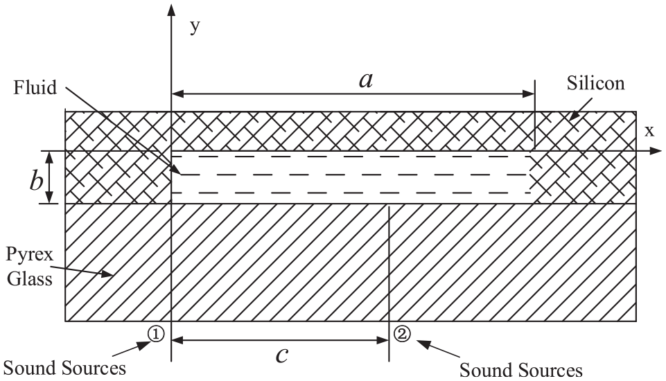
Ultrasonic wave is used as the external field to separate the suspended particles because the acoustic energy in the fluid produces an acoustic radiation force (ARF) on the suspended particles whose sound velocity and density are different from that in the fluid. Under the ultrasonic standing field, the suspended particles will move toward the wave knots or abdomen at the action of the ARF, and the magnitude of ARF will affect the particle migration time and the final position in the acoustic field. 2 As a general rule, solid particles are driven toward node planes of the ultrasonic standing wave sound pressure field. 23 In this paper, yeast is selected as the suspended particles, converge at the standing wave acoustic pressure node. The top view and cross-sectional view of the ultrasonic separator model based on the two-dimensional normal mode is shown in Figure 1. This separator is designed by layered resonance structure model, from bottom to top there are four layers: piezoelectric transducer (PZT), matching layer (silicon), fluid layer, reflection layer (Pyrex). Within the silicon wafer, a fluid channel is etched with a size of 0.2 × 8 × 30.5 mm2 (height × width × length). The height (Y direction) of the fluid channel has been designed to be equivalent to half of the wavelength of the ultrasonic standing wave. The separator is designed to form a two-dimensional ultrasonic standing wave field in the x and y directions in the fluid channel separation cavity to move the suspended particles to the corresponding position of the outflow port, the ultrasonic separation of the microfluid is realized. The smooth training wall near the inlet helps in establishing the laminar flow. The wedge shape training wall near the outlets helps to divide the clean and turbid streams more smoothly. This unique structure near the inlet and outlets effectively cut down the reflection of acoustic wave in Z-direction, and then the acoustic resonance in Z-direction can be avoided. This team uses two anti-phase PZT-transducers (the phases difference between PZT transducers is) on the bottom to excite the (1, 1) normal mode, and the feasibility has been demonstrated in the previous work. 16

Top view and cross-section view of the ultrasonic separator.
Two anti-phase PZT-transducers are attached on the bottom of the separator to excite anti-phase plane wave along x-direction (as shown in Figure 1). If the variation of sound wave after propagating through the matching layer is ignored, the sound source on the plane y = 0 can be written as
Assuming the inner wall of the fluid cavity to be rigid and resonances in the Z direction to be negligible, the wave equation based on two-dimensional normal mode (nx, ny) can be expressed as 24 :

The solution is:

It indicates that when nx is odd number, since the denominator in the coefficient expression will increase with the increase of Anx,ny, so when nx is equal to the minimum value of 1, the value of Anx,ny reaches the maximum, normal mode (1, ny) is the easiest one to be exited (1, 1) is selected in this paper.
In this paper, Ansys finite element software is used to support the working mechanism above and the experimental data behind. Assuming that all boundaries of the fluid cavity are rigid condition, and assuming that the sound pressure is uniformly distributed on each inner surface of the fluid cavity. At the bottom of the silicon wafer corresponding to the lateral width of the fluid cavity (b = 5 mm), two displacements of 1 µm in opposite directions with a distance of 1 mm are set to simulate the excitation of two anti-phase acoustic drivers. When the driving frequency is equal to the resonance frequency of (1, 1) normal mode, the acoustic pressure distribution in the fluid cavity of the separator viewed from the ANSYS analysis results is shown in Figure 2(b) .The x direction is the horizontal direction of the separation chamber, and the z direction is the flow direction of the fluid. The sound pressure icon from left to right indicates that the sound pressure increases from negative to positive. The green in the middle is close to zero, that is, the sound pressure in the center of Figure 2(b) is close to zero, where is the sound pressure nodal plane corresponding to the position of the standing wave sound pressure nodal plane in Figure 2(a), it indicates that the particles will converge on the plane in the center position in the x direction. When the first-order standing wave in the longitudinal direction (y direction) is also excited, the particles will converge into a bunch in the center of the separation chamber and flow out from the middle outlet of the separator. The results are consistent with the theoretical model of the standing acoustic wave formed in the X direction when the (1, 1) normal mode is excited, as shown in Figure 2(a).

Comparison of ANSYS simulation results and theoretical models in the fluid cavity: (a) theoretical model of X direction excited with two anti-phase PZTs and (b) simulation result of acoustic pressure distribution excited with two anti-phase PZTs.
Discussion
Based on the working mechanism of (1, 1) normal mode ultrasonic separation, this article discusses the influencing factors of ultrasonic separation efficiency, and summarizes two aspects: the coexistence of multiple modes of the separation cavity, insufficient absolute ARF.
Coexistence of multiple modes in the cavity
The cross-sectional width and height of the separation cavity of the ultrasonic separator are a = 8 mm and b = 200 µm, respectively, as shown in Figure 1. The resonant frequency of the two-dimensional (m, n) normal-mode may be expressed as 25 :
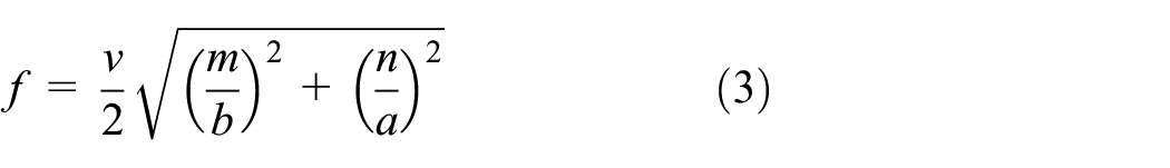
where

Schematic diagram of acoustic radiation force distribution under different excitating frequencies of different modes.
Insufficient acoustic radiation force (ARF)
ARF is a key factor affecting particle aggregation. The easiest way to improve ARF is to increase the sound pressure by increasing the amplitude of the voltage on both sides of the piezoelectric transducer. ARF will increase as the sound pressure increases. However, studies have found that excessively high voltage will cause severe energy loss when passing through the piezoelectric layer. Coupled with the resonance of the separation chamber, the temperature of the separation chamber will rise sharply, which will reduce the separation efficiency instead. In severe cases, the separator will be damaged. Laurell et al. 26 proved through experiments that the method of increasing the voltage does not work and also proved that when the (1, 0) order mode of the separator is excited, the suspended particles cannot converge due to insufficient acoustic radiation. The time average value of the ARF in the plane standing wave field can be expressed as,

where

Combining equation (4), it can be seen that the ARF amplitude of particles in the fluid is proportional to the third power of the particle radius, proportional to the normal frequency, and inversely proportional to the size of the separation cavity. This means that if the sizes a and b of the separator are appropriately reduced, the acoustic radiation force can be increased. The width of the high-throughput separator in this paper a = 8 mm is much larger than the width of the separator in Thomas Laurell’s experiment (width equal to 750 μm). When the mode (1, 1) in this article is excited, the problem of insufficient acoustic radiation force is unavoidable, which is also proved in subsequent experiments.
Influence of machining quality of the cavity
In the working mechanism, the condition of the (1, 1)-order normal mode excited by the double anti-phase PZTs is to assume that the four inner sides of the separation cavity are rigid side walls. The ultrasonic standing wave field in the separating cavity is formed by the superposition of the incident wave and the reflected wave. If the reflection surface of the cavity wall is rough, the incident wave will be diffusely reflected on the wall surface, so that a stable two-dimensional ultrasonic standing wave field cannot be formed; if the inner wall of the separation cavity is smooth and flat, specular reflection can occur, and the stable two-dimensional ultrasonic standing wave field can be formed. High-throughput ultrasonic separation based on the two-dimensional normal mode requires the processing quality of the inner surface of the separation cavity: the high precision of the depth of the separation cavity can ensure that the longitudinal excitation frequency is close to the theoretical value, which is the key factor for exciting the (0, 1) normal mode; The small verticality of the side wall and the bottom surface is conducive to the formation of lateral standing waves; the small flatness of the bottom surface and the side wall is conducive to occur specular reflection.
The ultrasonic separator in this article is composed of silicon and glass. The basic processing technique is to combine the separation cavity etched out of the silicon wafer with glass. Common etching methods include wet etching and dry etching. Common processing methods cannot meet the precision requirements of the separation cavity.
Optimization
Double acoustic sources excitation model
In order to solve the problem of the coexistence of multiple modes in the separated cavity when the (1, 1) mode is excited, this paper proposes a double acoustic sources excitation model, as shown in Figure 4. The position design of the acoustic drivers is a key factor for the (1, 1) mode to be excited successfully. Let us assume that the coordinates of the two acoustic drivers are (0, 0) and (c, 0) respectively. The frequencies of the two acoustic drivers are equal. Assuming that the vibration amplitudes in the y direction are equal, the entire vibration process is undamped, the system response is zero, and the fluid in the model is an ideal fluid with no attenuation of sound wave conduction. According to the sound wave interference theory and the wave equation, the surface wave displacement generated by the excitation of two acoustic drivers can be expressed as 24 :

Double acoustic drivers excitation model.
Where dsf0 is the amplitude of the vibration displacement in the Y direction, φ is the phase difference between the two surface waves, and ω is the excitation frequency of the acoustic driver.
Superimpose the displacement of the two acoustic drivers to get:

If

As shown in Figure 6 set the parameter

This article aims to excite the (1, 1) normal mode in the ultrasonic separation cavity. Combining Figure 3, it can be found that the (40, 0) and (2, 1) modes that are closest to the target mode frequency will be suppressed because M is an even number. And the acoustic displacement of (1, 1) modal excitation is twice that of a single acoustic driver, which means that the acoustic radiation force has also been greatly improved.
Sawtooth-shaped frequency sweep excitation
At fixed frequency excitation, particles are concentrated at the stable locations of the acoustic radiation force. Particle translation is achieved by a periodic sweeping of the frequency of excitation, which generates a slowly moving standing wave. Lipkens et al. 27 has investigated the effect of the sweep period and the sweep frequency range on particle translation speed, and through experiments proved that the particles velocities are inversely proportional to sweep period and proportional to frequency sweep range. According to Newton’s second law, the acoustic radiation force is also proportional to the sweep frequency range and inversely proportional to the sweep period.
The frequency sweep waveform usually has two kinds of sawtooth wave and step wave. Manneberg et al. 28 has proved through experiments that sawtooth scanning excitation is more conducive to improve the stability of the lines formed by particle aggregation than single-frequency excitation. Therefore, in this paper, sawtooth wave scanning is used to excite (1, 1) normal mode in the separation cavity. By appropriately increasing the scanning range and reducing the scanning period, the acoustic radiation of the particles can be improved.
Separator processing method based on micro-nano processing
In the common micro-nano manufacturing process, the easiest way to make a large-scale separator with a longitudinal depth of 200 μm in the cavity is to use a one-time etching molding technology, and the typical etching technology includes wet etching and dry etching. However, due to the shortcomings of isotropic etching in wet etching, it is difficult for these fabricating methods to simultaneously ensure the flatness of the inner wall, the depth accuracy, and the verticality of the cavity in the separator.
The micro-nano fabrication technology proposed in this paper is based on the semiconductor-based multilayer stack generation and high-precision alignment process, which ensures that the alignment error between the epitaxial patterns of each layer is within 0.3 μm. This effectively avoids vertical errors introduced by lateral etching in deep cavity fabrication.
1. Cavity structural generation
Step 1: Firstly, a SiO2 epitaxial layer with a thickness of about 20 μm is grown on a silicon wafer with a <110> crystal orientation, and then CMP (Chemical Mechanical Polishing technology) is used to realize the planarization of the wafer surface;
Step 2: Transfer the cavity pattern on the mask to the surface of the oxide layer by positive photoetching, and then remove all the oxide except the cavity area by a wet etching process.
Step 3: Silicon epitaxial 20 μm is grown by chemical vapor deposition method, then CMP is used to realize the planarization of the wafer surface.
Based on the alignment technique of the semiconductor planar-process, the first to third steps are repeated 10 times, and the three-dimensional structure of the separation cavity is designed through such a multilayer film growth technique. This process is shown in Figure 5(a), the yellow area SiO2 in the middle is the separation cavity, the final separation cavity structure is shown in Figure 5(b).
2. Cavity etching and molding

The fabrication process of the microseparator: (a) cavity structural generation, (b) structural molding, (c) waiting for etch back after etching, and (d) final structure.
All SiO2 in the cavity area are wet-etched with hydrofluoric acid to form a cavity, as shown in Figure 5(c).
3. Etchback cavity surfaces
Wet etching is used to etchback the all surfaces of the cavity, the alignment error between the various layers of the cavity is eliminated by isotropic etching of hydrofluoric acid and nitric acid, thereby the flatness of the sidewall of the cavity is improved, the final structure is shown in Figure 5(d).
In order to improve the processing quality of the inner wall of the separation chamber, micromachining technology is used in the processing of the separator. Observe the microstructure under a microscope, as shown in Figure 6. The image is very clear, the bottom surface of the cavity is very smooth and flat, and the etched lines of inlet and outlets are regular and clear. The surface finish quality is measured by Dektak 150 stylus profiler, as shown in Figure 7. The depth dimension of the cavity reaches 200 ± 0.5 µm, and the verticality of the side wall of the cavity reaches 83.36°. The degree of SFPD (Site Focal Plane Deviation) is less than or equal to 0.25 µm. Compared with the common etching method, the processing accuracy has been significantly improved.

The photomicrograph of the bottom surface of the separation cavity processed by micromachining technology.

The processing accuracy of the separator cavity measured by Dektak 150 stylus profiler.
Experiments
The experimental platform is set up as shown in Figure 8, two ultrasonic transducers are adhered to the left and right ends of the corresponding bottom of the separation cavity through silver conductive adhesive (S05001-AB) with high reflection coefficient, shown in Figure 8(a). Ultrasonic waves passing through the silicon matching layer are transmitted to the channel middle. The transducers are driven by a linear power amplifier (AG1017L, T&C Power Conversion, Inc.) which is connected to a function generator (33250A, Agilent) with resolution of. A syringe pump is used to supply suspended yeast fluid through the inlet. Finally, the behavior of particles is observed by a microscope camera (A101fc series, German BASLER) through the top layer of Preyx glass. And the captured results of camera can be easily transmitted to the computer with data wire IEEE1394.

(a) Photograph of the manufactured separator with two PZTs pasted on the bottom and (b) experimental arrangement with the manufactured separator.
The experiments in this article are all based on the separators processed by micromachining technology. Due to the low precision of common etching separators, they usually cannot capture any particle convergence. The normal mode of (1, 1) normal mode is excited by a single acoustic driver and a single resonance frequency, and the experimental results can be captured in repeated experiments, as shown in Figure 9. The Photo of the resonator is taken at time 3 min and 40 s. The particles in the separation cavity converge into lines in the X direction (i.e. the width direction). After partial magnification, we can calculate that there are exactly 40 lines, which indicates that the (40, 0) mode close to the resonance frequency of the (1, 1) mode is also excited. This experimental phenomenon has also been verified in ANSYS simulation analysis. It is also assumed that all boundaries of the fluid cavity are rigid condition, and assuming that the sound pressure is uniformly distributed on each inner surface of the fluid cavity. At the bottom of the silicon wafer corresponding to the lateral width of the fluid cavity (b = 5 mm), a displacement of 1 μm is distributed to simulate the excitation of a single acoustic driver. When the driving frequency is equal to the resonant frequency (1, 1) in the normal mode, the ANSYS analysis results are shown in Figure 10. To make it clearer, the sound pressure distribution of half the size of the fluid cavity of the separator is shown here. In the Figure 10, the standing wave above is set to help illustrate the position of the wave nodal surface in the simulation result below. There are exactly 20 standing wave sound pressure nodes, which means that the particles will converge on the 40 standing wave nodal planes in the X direction of the separation cavity. This is a good illustration of the experimental results in Figure 9. As analyzed in 2.1, when the separation cavity is excited by a single sound source and a single frequency, there is indeed a problem of multi-mode coexistence in the separation cavity, which is not conducive to the separation of particles.

Experimental phenomenon of the (1, 1) mode excited by a single acoustic driver and a single resonance frequency.

ANSYS simulation of the sound pressure distribution for half the size of the fluid cavity when a single driver is excited.
Combining the above schemes, a sawtooth frequency sweeping method with two anti-phase acoustic drivers is proposed to excite (1, 1) normal mode in the separation cavity. The sweep range is 2 kHz centered at the resonance frequency of (1, 1) mode 3.701 MHz, the sweep period is 1 ms. The PZT-4 transducers are driven by 10 V signals. The top view of the separation cavity taken by the microscope is shown in Figure 11. From the time the suspension was injected into the separation chamber, a large number of particles gathered in the center of the X direction in less than 10 s, and linear convergence was completely formed within 1 min and 39 s. Compared with the single-frequency single-source excitation technology, the particle gathering time of this technology is reduced by 2 min, and the particles converge into lines more clearly and stably. This experiment shows that the sawtooth frequency sweeping technology with two anti-phase acoustic drivers improves the response speed and stability of the concentration of suspended particles.

Experiment of saw-tooth frequency sweep with two anti-phase acoustic drivers: (a) photo of the resonator, taken at time 5 s. Particles are moving from all around to the center in the resonator, (b) photo of the resonator, taken at time 10 s. Particles continues to move to the center and coalesce in the center region of the resonator, and (c) photo of the resonator, taken at time 1 min and 39 s. The particles no longer move and converge to form a linear pattern.
Conclusions
This paper analyzes the excitation technology of (1, 1) mode ultrasonic separation of high-throughput ultrasonic micro-separator. There are two main factors that limit the success of excitation, one is the disorder of the acoustic field caused by the coexistence of multi-modes in the separation cavity, and the other is the lack of absolute acoustic radiation force (ARF), which leads to the inability of the particles to converge. In order to solve these two problems, this paper proposes to use integrated circuit micromachining technology to process the ultrasonic micro-separator, and an excitation method of saw-tooth frequency sweep of two anti-phase acoustic drivers, which can effectively suppress the multi-mode coexistence in the separation cavity and improve the ARF. To excite the (1, 1) mode, the depth dimension of the separator cavity determines the stable excitation of the first-order mode in Y direction, and the vertical rigid surface of the separator sidewall determines the stable excitation of the first-order mode in X direction. Ultrasonic micro-separators based on integrated circuit micromachining technology can reach micro-nano-level processing quality standards. The precise thickness process design of the multilayer film ensures that the depth dimension of the cavity reaches 200 ± 0.5 μm, and the nano-level high-precision plane alignment process ensures that the verticality of the cavity sidewall reaches 83.36°. After the cavity is etched and formed, through the etch-back process of the inner wall of the cavity the surface flatness of the cavity side wall is achieved less than or equal to 0.25 µm of the degree of SFPD (Site Focal Plane Deviation). The excitation method of saw-tooth frequency sweep of two anti-phase acoustic drivers replaces single driver with single frequency, which not only effectively suppresses the multi-mode coexistence in the separation cavity, but also improves the (ARF) and shortens the time for the pattern formation of particle convergence. Based on the interdisciplinary theoretical analysis, this paper proposes the fabrication method of the micro-separator and the excitation method of saw-tooth frequency sweep of two anti-phase acoustic drivers, which provides the research foundation and reference value for the practical applications of acoustic separation.
Footnotes
Handling Editor: Chenhui Liang
Declaration of conflicting interests
The author(s) declared no potential conflicts of interest with respect to the research, authorship, and/or publication of this article.
Funding
The author(s) disclosed receipt of the following financial support for the research, authorship, and/or publication of this article: The authors wish to thank the National Natural Science Foundation of China for financial support under grant number 50675031.