
Abstract
Micro-manufacturing is a fast developing area due to the increasing demand for components and systems of high precision and small dimensions. A number of challenges are yet to be overcome before the full potential of such techniques is realised. Examples of such challenges include limitations in component geometry, material selection and suitability for mass production. Some micro-manufacturing techniques are still at early development stages, while other techniques are at higher stage of manufacturing readiness level but require adaptation in part design or manufacturing procedure to overcome such limitations. This article presents a case study, where the design of a micro-scale, biomedical device is adapted for functionality and manufacturability by a high-volume micro-fabrication technique. Investigations are described towards a disposable three-dimensional, polymer-based device for the separation of blood cells and plasma. The importance of attempting a three-dimensional device design and fabrication route was to take advantage of the high-throughput per unit volume that such systems can, in principle, allow. The importance of a micro-moulding fabrication route was to allow such blood-containing devices to be cheaply manufactured for disposability. Initial device tests showed separation efficiency up to approximately 80% with diluted blood samples. The produced prototype indicated that the process flow was suitable for high-volume fabrication of three-dimensional microfluidics.
Keywords
Introduction
This article presents investigations towards a disposable three-dimensional (3D) polymer-based device for the separation of blood cells and plasma. This article is structured into three main sections. The first is about the design of the blood separator in terms of functionality and manufacturability, showing how to adapt a micro-scale, complex design of a biomedical device into a high-volume manufacturing technique. The second section focuses on fabrication procedure and considerations for micro-injection moulding (µIM). Finally, results from a prototype device are presented and assessed.
To introduce the topic, four areas of research are briefly summarised here: how blood plasma can be separated in microfluidic devices, why consider 3D devices, laminable layers as a method of producing such devices and the production of such layers by µIM.
Blood plasma separation by flow focusing
Blood plasma separation is an important step in several applications related to human health monitoring and disease diagnostics. 1 The presented microfluidic device offers an alternative blood separation approach to conventional plasma extraction techniques such as centrifugation, blood filtration or compact disk (CD)-like platforms. It depends in operation on several biomechanical separation principles that are combined to produce a separation between plasma and whole blood within micro-channels.
Briefly, the three principles of separation are outlined as follows.
Laminar flow. When blood flows at relatively low Reynolds number (0.01–1) in micro-channels of dimension comparable to the cells’ dimension, red blood cells (RBCs) exhibit a number of flow behaviours that cause the cells to concentrate at the centre of a microfluidic channel, creating a plasma-rich layer adjacent to the channel walls.
Flow focusing. The movement of RBCs in the blood flow is dependent on the magnitude of shear forces exerted on the cells. This relation has led to the assumption that the existence of a constriction in the blood flow will create a zone of high shear stress, which pushes the cells to the middle of the flow, creating a flow focusing effect as shown in Figure 1.
Bifurcations. RBCs exhibit a specific behaviour in bifurcations. As shown in Figure 2, at bifurcations, RBCs have the tendency to travel to the high-flow-rate channels, with the largest cross section, while plasma tends to move in low-flow-rate channels. One condition for this effect is that the flow rate ratio is at least 2.5:1.
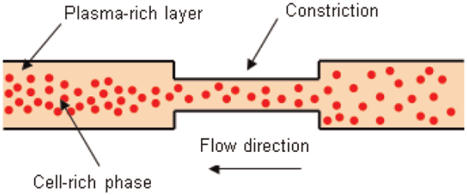
An illustration of the flow focusing effect of microfluidic constriction.
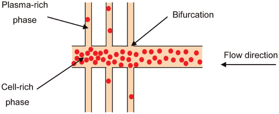
An illustration of the plasma separation effect caused by bifurcations.
More details about the haemodynamic effects involved in the above three principles can be found in the literature.1–3
3D microfluidic devices
A major design limitation in microfluidics is the geometrical constraint, which limits the majority of designed microfluidic devices to ‘flat’, so-called 2½-D, structures. These are usually defined as two-dimensional (2D) structures with a finite depth. 4 Due to the increasing demand for more complex microfluidic devices, there is a need for high-volume techniques to manufacture relatively complex, truly 3D microfluidic systems. Such true 3D structures, also sometimes known as ‘out-of-plane’ or ‘vertical’ architectures, 5 offer the advantages of optimising the use of space to integrate more functionality or increase throughput.
Such advantages are evident in, for example, microfluidics, where transforming conventional 2½-D designs into truly 3D devices could render higher throughput within a constrained volume. 6 In addition, 3D structures have potentially more flexibility in terms of interconnection between the micro-component and the surrounding environment. In a true 3D microfluidic device, for example, interconnection positioning would not be limited to the plane of the microfluidic structure, as the case with conventional 2½-D devices.
Realising these advantages of 3D structures, the blood separator presented in the previous section would be more efficient in blood plasma separation if it was designed as an out-of-plane 3D structure rather than a flat chip. Section ‘Experimental’ will give more details about how separation efficiency and throughput is improved by such a design change.
Laminated microfluidics
Turning the blood separator design into a truly 3D structure would make it difficult to directly fabricate with a state-of-the-art mass-manufacturing method. One method for overcoming this would be to manufacture sub-components of the device with relatively simple geometries and assemble them in post-processing.
An approach to assembling microfluidic components to produce 3D structures is that of lamination. In the literature, a number of attempts have been reported in which 3D microfluidic devices have been fabricated by laminating, for example, paper and tape, 7 laser-cut thin-film plastics, 8 soft-lithographed elastomers 9 and multi-material layered microfluidics.10,11 Common limitations of these approaches include the following. 5
The reported examples implement prototyping techniques that are not particularly intended for high-volume and low-cost production.
Some techniques are not suitable for fabricating layers with high aspect ratio microstructures.
Some techniques are limited to specific types of materials.
In light of such limitations, it would be an important step forward to use the capabilities of a high-volume micro-fabrication technique to produce laminated, polymer 3D microfluidic devices for disposable lab-on-a-chip (LOC) applications. This would combine both the flexibility of laminate microfluidics and the low cost associated with high-volume production. In this article, µIM is assessed as a potential candidate process for such an application due to its advantages, as highlighted in the next section.
µIM of laminable layers
µIM is a micro-replication technique that offers mass-production capabilities of polymeric, metallic and ceramic parts at relatively low cost and short-cycle times (a few seconds up to a few minutes). It has the potential for full automation, accurate replication and dimensional control. 12
In addition to high-volume manufacturing capabilities, µIM was particularly selected for this application because suitable mould design would enable the production of all sub-components in a single shot. This would avoid differences in shrinkage in sub-components. (More details about this are presented in sections ‘Design for µIM’ and ‘Design for micro-assembly’.)
Very few 3D laminate structures have been produced by µIM, where a ‘laminate structure’ in this case refers to a microfluidic multiple-layer structure and not simply a microfluidic substrate and lid. In one example, an LOC device was designed for detecting metabolic parameters,13,14 where three to four layers of micro-moulded thermoplastics were fabricated and joined by thermal fusion.
In spite of the considerable potential of the technique, little has been mentioned in the literature on how to design a microfluidic laminate structure for manufacturing by µIM; specifically, how to adapt the device design for manufacturing limitations, namely, mould making and replication, how to consider design for assembly options and how to deal with possible contradictions between different design constraints.
Experimental
The approach taken to designing a micro-mouldable laminate microfluidic device was to assess the design limitations of each activity in the process flow and then resolve potential conflicts between different design requirements. The approach balanced the functional requirements of the device (dimensions, tolerances, etc.) with the manufacturability limitations of the process (µIM in this case). Figure 3 summarises this approach.
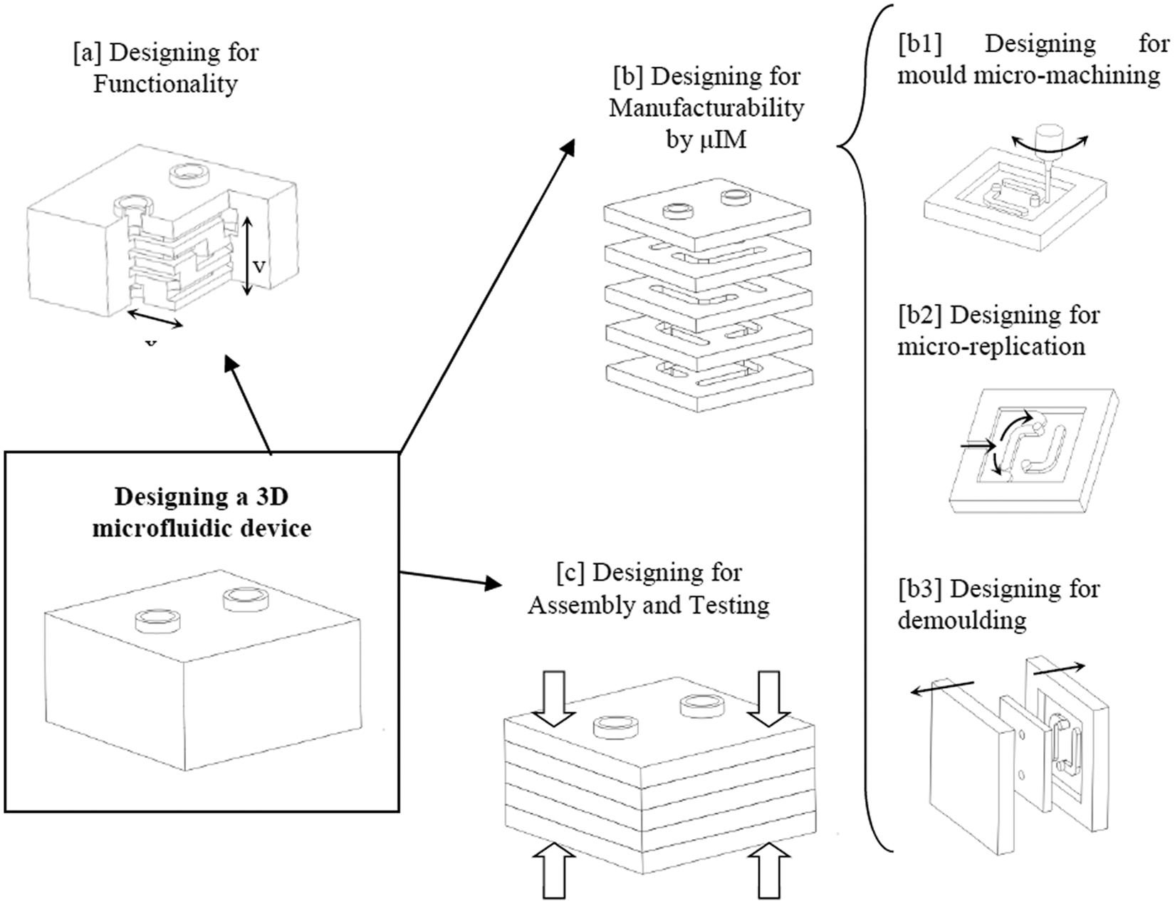
An illustration of the design approach to produce 3D microfluidic devices by µIM.
Designing for functionality was a first priority in the process; fluid channel sizes, tolerances and orientations were determined (step [a]). The device ‘layers’ were designed to be micro-mouldable without compromising the functionality of the device (step [b]).
In µIM, as a net-shape micro-fabrication method, part design must involve assessing the three major steps of the process: mould machining, feature replication and demouldability (denoted in Figure 3 as steps [b1], [b2] and [b3], respectively). Each of the three steps had its design limitations in the micro-scale manufacturing.
The third major design consideration was joining the layers to produce a leak-proof system (step [c]). This involved not only designing for a specific joining technique but also considerations of part separation and handling, alignment techniques and testing. The design stages are considered in more detail below.
Design for functionality requirements
The main functional requirements of the device were categorised into the following main groups.
Dimension-related requirements
1. Laminar flow. Plasma flow is laminar in microfluidic channels with hydraulic diameter ranging from 10 to 500 µm. 1 In addition, after the constriction zone, the blood flow should go into a bifurcation zone, where the plasma separates from the main flow path and is then extracted from a separate output. The flow ratio between the main channel and the side paths should be at least 2.5:1.
2. Flow focusing. A constriction zone is required in the blood flow path to induce a high shear zone for flow focusing. From the literature, there are no specific guidelines on the dimensions of the constriction relative to the main flow path.
Geometry-related requirements
3. High throughput. A 3D structure of the microfluidic device would allow for potentially higher throughput of the device, more flexibility in interconnection design and the possibility of future integration into a total analysis cell. Concerning separation efficiency, increasing the number of sequential bifurcation points will increase the separation yield. However, as the number of bifurcation points increases, the flow rate of plasma in the side channels decreases to the extent that no more plasma is extracted from the last bifurcations. A flexible design would be required to change the number of bifurcation points when desired.
Assembly-related requirements
4. Interconnection. The device should be connectable to surrounding environment.
5. Leak-proof system. The microfluidic device should be designed to minimise possible leakage of fluidic samples, especially in bonding/joining positions.
Material-/manufacturing-related requirements
6. Optical transparency. This is required to observe the flow inside the channels during testing stage, but may also be useful for the device in service so that any channel clogging can be observed.
7. Biocompatibility. The device material should be suitable for blood flow applications.
8. Disposability. The device should be designed such that it is manufacturable by a high-volume technique that allows for low-cost disposable devices.
Conceptual design
Figure 4 presents a design for the blood plasma separator based on the functional requirements outlined in the previous section.
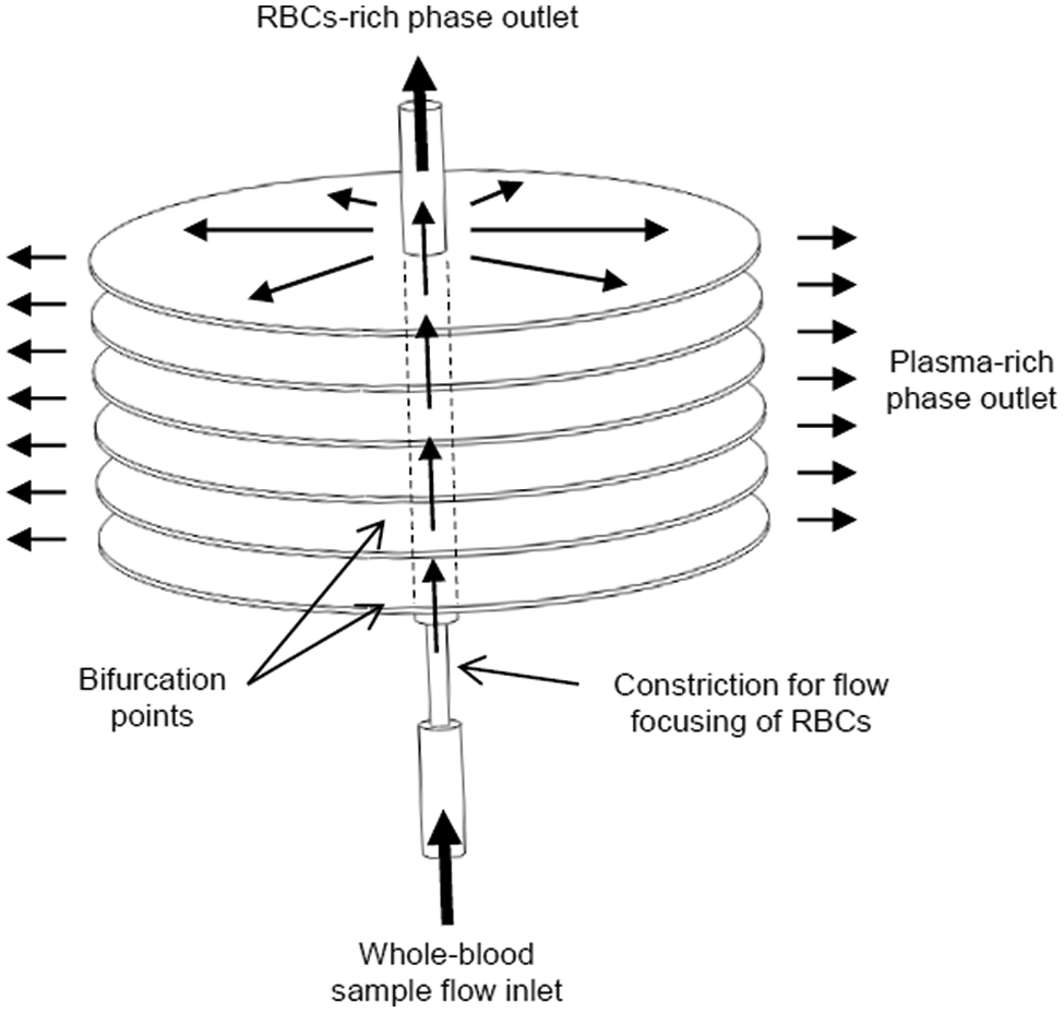
An illustration of the 3D plasma separation microfluidic device.
The device consists of an inlet channel where the continuous flow of a blood sample is induced at a controlled flow rate. The diameter of the microfluidic channel was selected to be 400 µm to ensure continuous laminar conditions as stated in section ‘Dimension-related requirements’.
A constriction is placed after the inlet to induce the flow focusing effect resulting from high shear conditions. Since no recommended dimensions were available in the literature, the dimensions were selected as 100 µm in diameter and 600 µm in length.
After the flow focusing zone, a number of bifurcations were introduced to separate the plasma from the main flow. Instead of conventional 2½-D bifurcations usually presented in literature, the design was based on 3D bifurcations, where microfluidic ‘surfaces’ intersect with the main flow path allowing for a relatively larger amount of plasma separation. The thickness of each separation space was selected to be 50 µm.
Since separation yield is directly related to the number of bifurcations, the design was made to accommodate a number of separation layers across the flow path. In total, 20 bifurcations were suggested as a maximum for a 2½-D design to avoid having excess channels that do not extract any plasma. 1 With the available knowledge, the optimum number of bifurcations is a matter of trial and error, so the 3D structure was designed such that the manufacturing process allows for the flexibility of adding extra separation cavities when needed.
Numerical simulation tests were made to evaluate the effect of the selected dimensions on the separation efficiency of the 3D device and of possible geometry modifications. The simulations were performed using a developed computational fluid dynamics (CFD) code in ANSYS CFX5. The simulations demonstrated that separation throughput for the 3D design is much higher than a 2½-D design, because the cross section of the main channel and the coupled intersection between the main and side channels are largely increased in the 3D separator, leading to a much higher throughput and separated flow rates than the 2D separator.15,16
Design for µIM
Designing for demouldability
Similar to conventional ‘macro-scale’ injection moulding, µIM poses a number of limitations on mouldable part geometries. The major limitations are related to the demouldability of the part, that is, separating the moulded component from the mould at the end of the injection process. Design considerations include, 17 for example, the location of the parting line (separation surface between the two mould halves), introduction of draft angles (tapering of vertical surfaces aligned with the opening direction of the mould) and elimination of undercuts (elements that prevent either the core mould-half from being extracted after the component has been formed or the component from being ejected out of the cavity). 18
The latter design consideration, that of undercuts, is the main design concern in this case study since this is what prevents the direct fabrication of 3D microfluidic components by injection moulding. As a result, the design shown in Figure 4 would not be producible by µIM as a single part due to geometrical complexity that prevented it from being directly demouldable. It was, therefore, necessary to adapt the design to the geometry limitation of the process, and the approach followed in this case was to produce the device as a number of parts that could be assembled in a subsequent assembly process.
The device was designed as a laminate of mouldable layers. Figure 5 illustrates how the microfluidic device in Figure 4 was adapted to µIM by transforming it into a laminate structure. The dotted lines highlight suggested separation levels, which would eventually render a set of demouldable 2½-D layers.
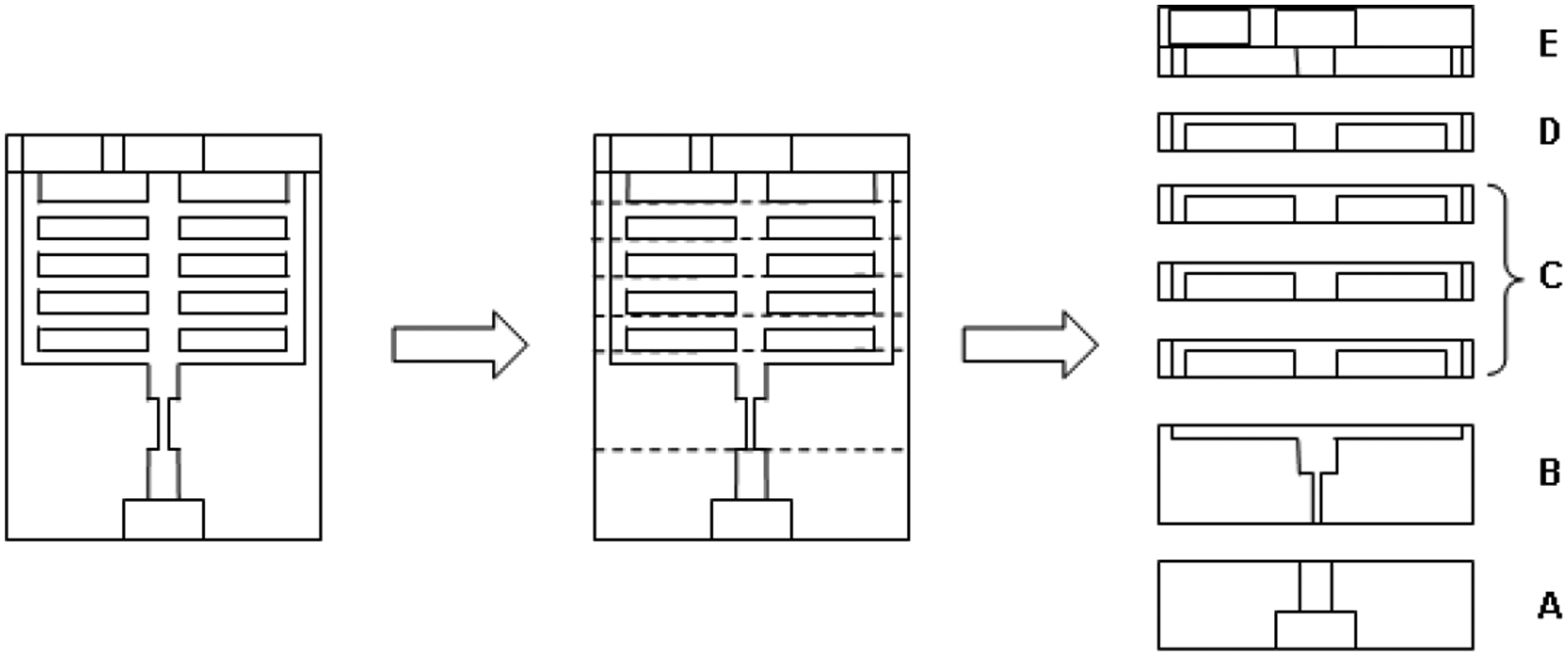
Transferring a 3D structure into a laminable structure. All individual layers are 2½-D in structure. Extra layers of C correspond to extra separation bifurcations.
The design in Figure 5 features five layers, denoted by A–E, where each layer performs a specific function or functions. Although not obligatory to the design process, this meant that repeats of functionality would be achievable simply by adding more layers of a particular type. All the layers are effectively demouldable in the sense that they all feature undercut-free, 2½-D geometries that could be ejected from basic two-half moulds. Layer functionality was as follows.
Layer A. An input port for tube interconnection and sample delivery.
Layer B. A multi-functional layer, which contains both a constriction for flow focusing and a separation depression.
Layer C. A stackable separation surface (bifurcation junction). Theoretically speaking, this layer could have been omitted from the design since separation is already performed in Layer B. However, it was designed as a repeatable unit to meet the requirement for expandable bifurcations.
Layer D. A plasma collection channel.
Layer E. Output port for tube interconnection and extraction of both RBC- and plasma-rich phases.
Designing for micro-replication
A major challenge in µIM is the ability to fill micro-size cavities in the mould. Filling quality is a factor of several interdependent parameters, including mould geometry (e.g. feature sizes, aspect ratios 19 ), mould surface properties,20,21 polymer thermal and viscoelastic properties 22 and processing conditions.23–26
For the blood separator, the critical replication challenge was to accurately create the through-hole micro-features located at each of the five layers. Each layer was designed with thickness of 1 mm to allow for stable material flow inside the cavity during moulding. In addition, the runner and gate system was designed to supply enough volume of filling material inside the mould cavity to avoid premature freezing. Process conditions were also optimised for complete part filling.
Designing for mould micro-machining
The mould was designed to be manufactured as a set of five interchangeable elements that produced the features of the five layers of the device. Five microstructured aluminium inserts, the carrying steel holder and the mould housing all fit together within an H7 transitional fit. This reconfigurable structure was selected to allow for the flexibility of changing the design and/or re-machining the features when deemed necessary. The time and cost involved in machining moulds, especially with micro-features, make it a high risk to machine the whole mould as a single piece. This manufacturing path was selected as an alternative approach for prototyping purposes.
When designing the parts, micro-machining limitations were taken into consideration. The main concern was the aspect ratio of the micro-features, which is limited by the dimensions of the micro-milling cutting tools used. Considering that the overall thickness of each layer was 1 mm, the maximum aspect ratio in all the parts was 5, which was safely below the reported maximum aspect ratio of micro-milling, which is approximately 10–15.27,28
It should be noted that micro-milling poses other limitations in terms of, for example, surface finish (Ra = 0.3 µm), feature accuracy (3–10 µm) and burr generation. In this particular case study, these aspects were not critical to the part design, given the functional dimensions noted in section ‘Design for functionality requirements’.
Design for micro-assembly
Designing for assembling micro-moulded parts requires the consideration of a number of issues including, 29 for example, the use of the runner system as a handling tool, the effect of parting line marks, draft angles and gate location. In addition, it is advisable to avoid bonding microfluidic laminates directly over voids created by, for example, channels or reservoirs. 30
The blood separator was designed such that the separator layers could be stacked and bonded between flat mating surfaces using a suitable polymer-joining method. Several design elements were incorporated to aid post-moulding assembly.
All the layers were designed with axially symmetric features, such that no specific axial orientation was required between adjacent layers. This limited the requirements of assembling to alignment rather than both alignment and orientation.
The layers were all designed in circular shapes of equal diameters. When the parts would be stacked for welding, the outer diameter of the layers would be selected as the alignment edge. This registration approach, also known as ‘edge-alignment’, 5 relies on using a jig to align laminated layers using edges or corners. The jig was designed to align the parts without interference from side-gate marks that might result from separating the parts from the runner system.
The outer diameter of the layers was set to 10 mm with the separation features located in the centre of the parts. This allowed for a peripheral area, usable for the joining process, that was away from the microfluidic features, to minimise feature deformation that might compromise the functionality of the device.
It should be noted that when joining laminates, the flatness of the mating surfaces was critical for ensuring leak-proof joints. In the case study presented in this article, the flatness of the joining surfaces was minimised during the micro-moulding process using statistical quality control. 31
Micro-mould manufacture
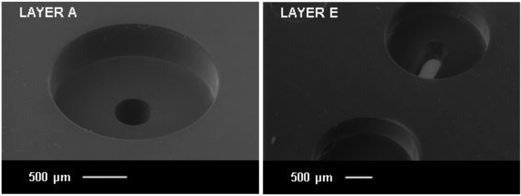
The mould inserts shown in Figure 6 were manufactured by micro-milling using a KERN micro-milling centre. The surface finish of the micro-features of two of the aluminium mould inserts is shown in the micrographs of Figure 6. It should be noted that due to its full axial symmetry requirement, Layer A was finished with diamond turning for a better surface finish.
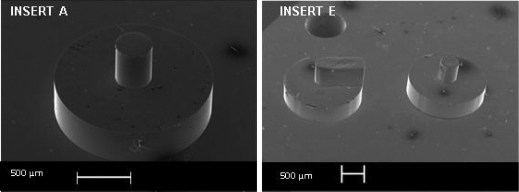
SEM micrographs of the Layer A and Layer E microstructured mould inserts.
Micro-replication of component parts
The polymer layers were moulded with a Battenfeld Microsystems 50 µIM machine. The material used was polymethylmethacrylate (PMMA) of the grade Altuglas® VS-UVT. The grade was selected for its ease of flow (melt flow index (MFI) = 24 g/10 min), optical transparency (light transmittance = 92%) and compatibility with medical applications involving blood. It was also compatible with ultrasonic welding.
A design-of-experiment approach was implemented to optimise processing conditions for complete filling of the features.32–34 The optimised process conditions were selected as shown in Table 1. The cycle time for the one moulding operation was approximately 5 s.
Processing parameters for a five-part micro-moulded component.
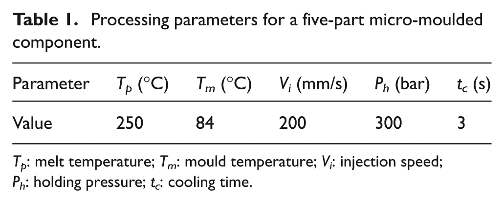
Tp: melt temperature; Tm: mould temperature; Vi: injection speed; Ph: holding pressure; tc: cooling time.
Results and discussion
Figure 7 shows a photograph of the moulded parts, while Figure 8 shows scanning electron microscopy (SEM) micrographs of plastic Layers A and E.
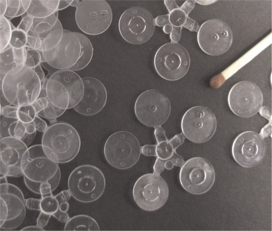
Micro-injection moulded plastic components.
SEM micrographs of PMMA micro-moulded components: Layers A and E.
Defibrinated horse blood was used to test the functionality of the device. In order to achieve higher separation efficiency, several separation layers (C-type layers) were added to the tested device. A preliminary assembly was created using a commercial PMMA-compatible adhesive using a pre-designed fixture system. The layers were aligned based on their external edges, and the assembled prototypes were inspected under the microscope, where observed misalignments were in the order of 10 µm. Some deformations related to the flatness of the mating surfaces of the layers were observed. They were found to be due to the ejection forces of the ejector pins. These deformations were detected and minimised using a design-of-experiment approach, where further details are available in the literature. 31
The assembled device was then immersed in a resin to enable cross sectioning and polishing for optical inspection. Figure 9 presents an image of an assembled device, with the fitted tubes, while being proof-tested with water.
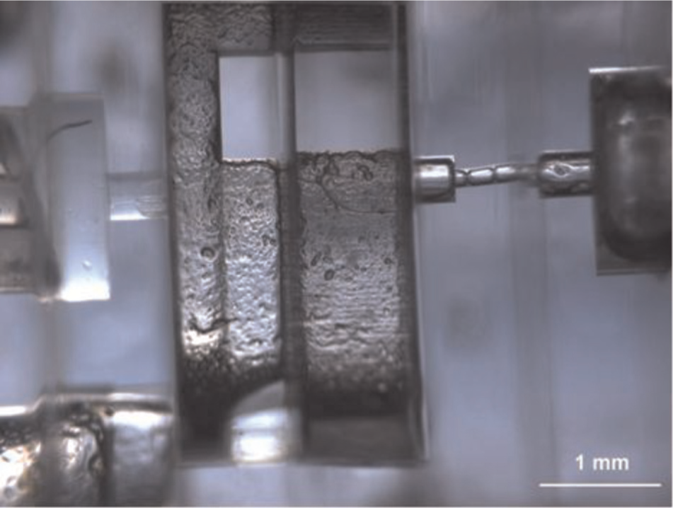
An assembled device being tested with water. The five layers, A–E, run from left to right across the optical micrograph, with the flow focus constriction in Layer B. An inlet tube is inserted into the device, centre left.
Figure 10 shows a recording of the test, taken using a digital video camera.
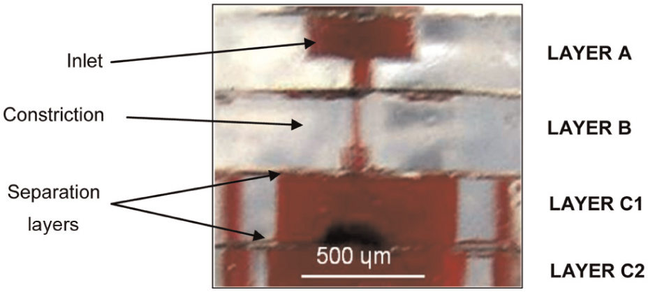
Blood flow through an assembled separator.
Diluted samples (1:20) of horse blood were pumped into the device at a rate of 0.35 mL/min. Separation was assessed for a device model, which contained three separation layers (one B-layer and two C-layers). Separation efficiency was characterised by plasma selectivity (σ) defined as
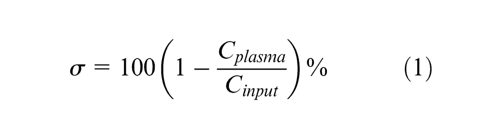
In equation (1), Cplasma and Cinput are the concentrations of RBCs in the sample collected at the plasma outlet and in the whole blood sample, respectively. A plasma selectivity of 100% implies that the plasma is completely free of RBCs. The selectivity measured for this particular experiment was 79.9%.
It should be noted that there are a number of limitations that need to be addressed with regard to the presented design. One limitation is the complexity of the design. Increasing the complexity of the geometry results in increased processing steps, such as alignment and joining. This potentially increases the fabrication cost and time, in addition to increasing risk of leakage. Automation of the process is key to achieve controlled process of manufacturing and joining. Another limitation is the sample dilution, which was selected deliberately high for testing purposes. Using the device for separating concentrated blood samples requires better control of feature dimensions and surface properties. Mould making should be done with a manufacturing technique that offers better control over dimensions and surface properties, such as micro–electric discharge machining (EDM).
Conclusion
This article described a case study of adapting high-volume micro-fabrication technique to realise a complex 3D component. This was illustrated through designing and fabricating a prototype disposable 3D polymer-based device for the separation of blood cells and plasma. The design goal of a 3D structure was to investigate the potential for 3D maximisation of throughput and separation efficiency.
This article indicated the design stages required in such an approach: design for functionality, design for manufacturability and design for assembly and testing. It showed how the micro-moulding of individual micro-parts with different functionalities followed by their lamination could be used to achieve the goal of a 3D blood separation device.
The designed structure was replicated by µIM of PMMA, as five different laminable layers. The required micro-features were successfully replicated. Layers were successfully edge-registered and assembled. Separation tests of diluted animal blood samples in manually assembled devices showed successful separation of RBCs and plasma to a 79.9% efficiency.
Footnotes
Declaration of conflicting interests
The authors declare that there is no conflict of interest.
Funding
This work was supported by the UK Engineering and Physical Sciences Research Council (EPSRC) through the Grand Challenge Project ‘3D-Mintegration’, ref. EP/C534212/1.