
Abstract
In the electro-hydraulic servo control system, there are some problems, such as low position control accuracy, uncontrollable speed, speed impact, and asymmetric control due to the asymmetry of hydraulic cylinder. To solve the above problems, this paper proposes a Fuzzy PID control algorithm with load force compensation based on improved PSO optimization. This improved particle swarm optimization algorithm introduces crossover and mutation operations in genetic algorithm to improve the optimization performance of traditional particle swarm optimization algorithm. The mathematical model of valve controlled asymmetric cylinder is established, and the Amesim linearization analysis function is used to identify the system, establish the transfer function, and build the control system. The joint simulation and test results of Amesim and MATLAB show that the proposed control strategy can realize the simultaneous control of speed and position. Under different loads, different speeds, and different input follow signals, it does not need to adjust any parameters. Regardless of forward or reverse operation, the optimal dynamic performance and minimum steady-state error are obtained, which greatly improves the response speed of the system. The effectiveness and superiority of the improved PSO compound control strategy are verified.
Preface
There are many research reports on electro-hydraulic position servo system and speed servo system at home and abroad. The application of control theory and various control strategies can improve the steady-state control accuracy and dynamic performance of the system1–7. However, there is still a problem that the symmetrical valve controlled asymmetric hydraulic cylinder has the problem of asymmetric control, especially in the control occasions with large load and high precision, and when the load changes in a wide range, this phenomenon is more prominent.
This paper takes the system with hydraulic cylinder symmetry control and large-scale variation of load force as the research object, and studies the corresponding control strategy. At present, the high-performance control of this asymmetric hydraulic servo system has attracted more and more attention. In order to compensate the asymmetry of asymmetric hydraulic cylinder, reference 8 adopts multi-stage sliding mode robust adaptive control method to accurately track the piston displacement. In reference, 9 aiming at the non-linearity, time-varying internal parameters, and external load disturbance of electro-hydraulic position control system, an active disturbance rejection composite control method based on load force compensation is adopted. Reference 10 studies the application of predictive iterative learning control with forgetting factor in valve controlled asymmetric cylinder system. Reference 11 proposed a double fuzzy control algorithm with compensation factor to solve the asymmetric problem of electro-hydraulic servo valve controlled asymmetric cylinder. In reference, 12 active disturbance rejection control technology is applied to electro-hydraulic speed servo system. The solutions proposed in the above literature have achieved good control results in compensating the asymmetry of asymmetric cylinder, but the algorithm design is complex. There are some difficulties in the application of real-time control system.
Particle swarm optimization algorithm has the advantages of simple operation, strong robustness, and fast convergence. It is used to optimize nonlinear systems in literature.13–18 However, the traditional particle swarm optimization algorithm is easy to fall into the local optimal solution. At present, the improved particle swarm optimization algorithm introduces other control methods or intelligent algorithms to deal with complex objects. Literature 19 applies the classified learning particle swarm optimization algorithm to the control of hydraulic straightener. Reference 20 combines particle swarm optimization algorithm with simulated annealing algorithm to deal with nonlinear problems, which improves the efficiency and search quality of the algorithm. Reference 21 used the improved particle swarm optimization algorithm to optimize the parameters of PID controller for position control system of nonlinear hydraulic system. Reference 22 presents a novel PSO with adaptive inertia weight to rationally balance the global exploration, the inertia weight is dynamically adapted for every particle by considering a measure called adjacency index (AI), it can simulate a more precise biological model, the inertia weight is variable with the number of particles. Every particle dynamically adjusts inertia weight according to feedback taken from particles’ best memories. The main advantages of the novel PSO are to achieve faster convergence speed and better solution accuracy with minimum incremental computational burden.
At present, there is little research on particle swarm optimization algorithm in hydraulic servo control. Based on the analysis of the working principle of the valve controlled asymmetric cylinder, considering that the force area of the non rod cavity is greater than that of the rod cavity when the hydraulic cylinder is extended, resulting in the problem that the retraction tracking error is greater than the extension tracking error when the position servo tracking of the asymmetric cylinder, the crossover and mutation operations in the genetic algorithm are introduced into the PSO algorithm, an electro-hydraulic servo Fuzzy PID compound control strategy with load force compensation based on improved PSO algorithm is proposed to eliminate the influence of external load change on speed, effectively solve the asymmetric problem of electro-hydraulic servo valve controlled asymmetric cylinder, and has good control effect. The purpose of this paper is to use a relatively simple and easy to implement method to solve the control problem of asymmetric electro-hydraulic servo system with low operation cost. This study is meaningful from the perspective of engineering application, it is hoped that it can be popularized and applied in the field of electro-hydraulic servo control.
System description and modeling
The composition principle of valve controlled asymmetric cylinder speed/position composite control system is shown in Figure 1, including electro-hydraulic servo system and force loading system. It is mainly composed of active hydraulic cylinder, loading hydraulic cylinder, servo valve, hydraulic pump, pressure sensor, displacement / speed sensor, data acquisition, and computer control system. The diameter of the hydraulic cylinder is 63 mm, the diameter of the piston rod is 36 mm, and the stroke is 300 mm; The servo valve is WDPFA10-acb-s-65 of WANDFLUH company, its response time is less than 20 ms, and the rated flow is 65 L/min when the differential pressure is 3.5 MPa.
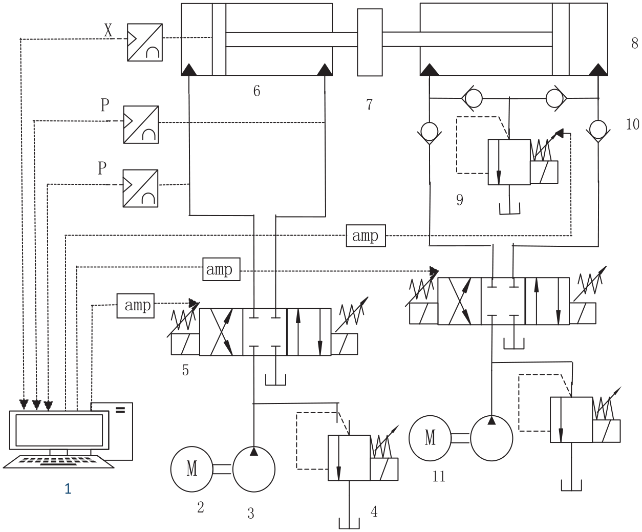
Schematic diagram of system composition.
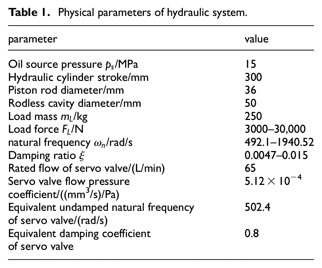
The hydraulic cylinder parameters used in the experimental platform are shown in Table 1.
Physical parameters of hydraulic system.
Linearized flow equation of hydraulic servo valve
In the valve controlled cylinder electro-hydraulic servo system, the flow of the electro-hydraulic servo valve can usually be approximately expressed by the following linearization equation 21

Where,
In most servo systems, the dynamic response of servo valve is often higher than that of power components. In order to simplify the analysis and design of dynamic characteristics of the system, the transfer function of servo valve displacement to input current can be approximately expressed by proportional link.

Transfer function of servo amplifier and displacement sensor
The servo amplifier is a voltage current converter with high output impedance. The frequency band is much higher than the hydraulic natural frequency, which can be simplified as a proportional link.

The transfer function of displacement sensor can be regarded as a proportional link, and the transfer number is

Flow continuity equation of hydraulic cylinder
The connecting pipeline between the valve and the hydraulic cylinder is symmetrical, and the pressure loss and pipeline dynamics in the pipeline can be ignored. The pressure in each working chamber of the hydraulic cylinder is equal, and the oil temperature and bulk elastic modulus are constant. Both internal and external leakage of hydraulic cylinder are laminar flow, and the load flow equation of asymmetric hydraulic cylinder is 14

Where,
Balance equation between hydraulic cylinder and load force
In this system, inertial load is the main load, viscous and elastic load are ignored, according to Newton’s second law. The balance equation between output force and load force of hydraulic cylinder is

Where,
After Laplace transformation of equations (1), (5) and (6), the following equations are obtained


By eliminating the intermediate variable, the output displacement of the piston is

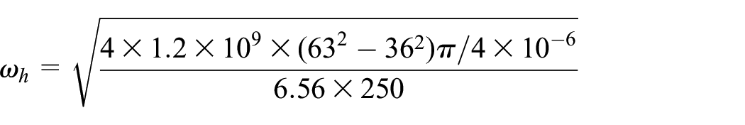
Where, the hydraulic natural frequency is

Hydraulic damping ratio is

Total flow pressure coefficient is

The transfer function for instruction input

The transfer function models of each link are given above, which together constitute the mathematical model of electro-hydraulic servo valve controlled asymmetric cylinder.
Valve controlled asymmetric cylinder model identification
The hydraulic valve controlled cylinder system is a strong nonlinear system, which is mainly reflected in the pressure flow nonlinear characteristics of the valve, the change of the volume of the two chambers of the hydraulic cylinder caused by the piston movement, the compressibility of the oil, the nonlinear friction of the hydraulic cylinder, the saturation characteristics of the valve, and the change of the leakage flow of the valve and cylinder with the oil supply pressure. Working point linearization is a common method for nonlinear system analysis. The hydraulic valve controlled cylinder system is a third-order system composed of an integral link and a second-order oscillation link. Because the theoretical calculation is complex, the workload is large, and some assumptions and simplification are made in the derivation of the linear model, which affects the accuracy of the results. The system identification method needs strong theoretical basis, a large number of experimental data, and complex processing process.
Based on the above reasons, this paper uses Amesim linearization tool 23 to analyze and obtain the transfer function of hydraulic valve controlled cylinder system, and compares it with theoretical calculation.
Firstly, a valve controlled asymmetric cylinder electro-hydraulic servo system composed of hydraulic cylinder, servo valve/proportional valve, oil source, displacement sensor, and controller shall be established. A simple proportional controller shall be used to form a closed-loop control system to make the system enter the steady state. The Amesim model of the system is shown in Figure 2.

Amesim model of electro-hydraulic positionclosed-loop control system.
Firstly, set the system variables, and then set the parameters of each component and oil source of the hydraulic system in the Figure 2. Take the hydraulic cylinder used in the test platform in this paper as an example, see Table 1.
Set the given displacement value to 0.2 m, and conduct linearization analysis after the system enters the steady state. The eigenvalue analysis results are shown in Figure 3.

Eigenvalue analysis results of valve controlled asymmetric cylinder.
Figure 3 eigenvalue analysis results of valve controlled asymmetric cylinder. Around 80 Hz frequency and 0.8 damping ratio are the characteristics of servo valve. The other two complex roots and one real root are the dynamic link eigenvalues from servo valve spool displacement to hydraulic cylinder piston speed. The servo valve spool displacement to hydraulic cylinder piston speed is the second-order oscillation link, and the natural frequency and damping ratio are 78.36 Hz and 0.0047 respectively. In MATLAB, the “ameloadj. M” tool is used to read the four matrices of the state space model obtained by linearization analysis. The command format is: >>[a, B, C, D] = ameloadj. Further, the state space model is transformed into a transfer function in the form of zeros and poles by the command >>[Z, P, k] = ss2zp (a, B, C, D). The dynamic characteristics of the servo valve control input to the piston speed of the hydraulic cylinder have one zero point and five poles, the zero point is −0.5506, and the poles are exactly the same as those shown in Figure 5. There is a real pole which is the same as the zero point and offsets each other, because the pressure in the two chambers of the hydraulic cylinder is related, not independent.
The transfer function of valve controlled cylinder system from servo valve spool displacement to hydraulic cylinder piston displacement can be expressed as:

The damping ratio

The natural frequency of the second-order oscillation link is deduced theoretically


The theoretical calculation results are almost consistent with the Amesim linearization analysis results, so the identification model of valve controlled asymmetric cylinder is more accurate.
System control strategy design
Controller design
For the large-scale variation of load force and symmetrical electro-hydraulic servo valve controlled asymmetric cylinder system, the parameter adaptive Fuzzy PID can adapt to the situation of large-scale variation of load. However, because the symmetrical valve controlled asymmetric cylinder will cause the problem of control asymmetry, only the parameter adaptive Fuzzy PID can reduce the problem of asymmetry to a certain extent, but the effect is limited, it can not meet some high-precision control occasions. If it can be combined with intelligent optimization algorithm and compensation control strategy, it can compensate the asymmetry of hydraulic cylinder and improve the control accuracy of the system. Therefore, Fuzzy PID and load force compensation control strategy based on improved particle swarm optimization is proposed in this paper. The system control block diagram is shown in Figure 4.

System control block diagram.
Particle swarm optimization
Particle swarm optimization (PSO) is a population optimization algorithm based on the study of bird predation behavior. Firstly, particle swarm optimization algorithm will randomly generate a particle swarm in the feasible solution space, and each particle represents a feasible solution. Particle characteristics are represented by position, velocity, and fitness. During the operation of the algorithm, the particles continue to move to the optimal position, that is, the optimal position of fitness value. The position and velocity of the particle itself are updated by individual extremum and group extremum. The formula is as follows 20


Where,
Improved particle swarm optimization algorithm
The traditional particle swarm optimization algorithm updates the position of particles by tracking extreme values, which has the advantages of simple operation, fast convergence, and good robustness. However, in the process of continuous iteration, the particles tend to be similar and are easy to fall into local optimization. In order to improve the traditional particle swarm optimization algorithm, the crossover and mutation operations of genetic algorithm are introduced into particle swarm optimization algorithm. In this improved particle swarm optimization algorithm, firstly, the fitness values of all particles are calculated, and all particles are sorted according to the fitness values. After sorting, discard the particles whose fitness value is worse than the average fitness value of particles. Then perform cross operation. The particles with better residual fitness are randomly crossed with individual extreme value or group extreme value to obtain new particles until the particle swarm size returns to the original number. The position of the new particle can be obtained by the following two formulas 24


Where,
The mutation operation mutates the particle itself. The better the particle fitness, the smaller the mutation probability. Assign a random number between [0, 1] to each dimensional position of all particles. When the random number corresponding to the

Where,
In this paper, the improved particle swarm optimization algorithm is used to determine the increment

Design of fuzzy adaptive PID controller
For complex systems with time-varying, nonlinear and multi disturbance, the conventional PID control can not adjust the parameters in real time, and the control effect often can not reach the ideal state. The fuzzy control module is introduced to realize the on-line self-tuning of PID parameters, so that the control effect has better robustness and control accuracy.
The Figure 5 shows

Structural block diagram of fuzzy adaptive PID control system.
The controller is two-dimensional input and three-dimensional output. The fuzzy language variables of hydraulic cylinder displacement deviation, deviation change rate, and control quantity are divided into {NB, NM, NS, ZO, PS, PM, PB}, which respectively represent negative large, negative medium, negative small, zero, positive small, positive medium, and positive large. The discrete universe of system input and output is {−3, −2, −1, 0, 1, 2, 3}. The input and output membership function is determined after many field investigations and practical operation experience, as shown in Figure 6.
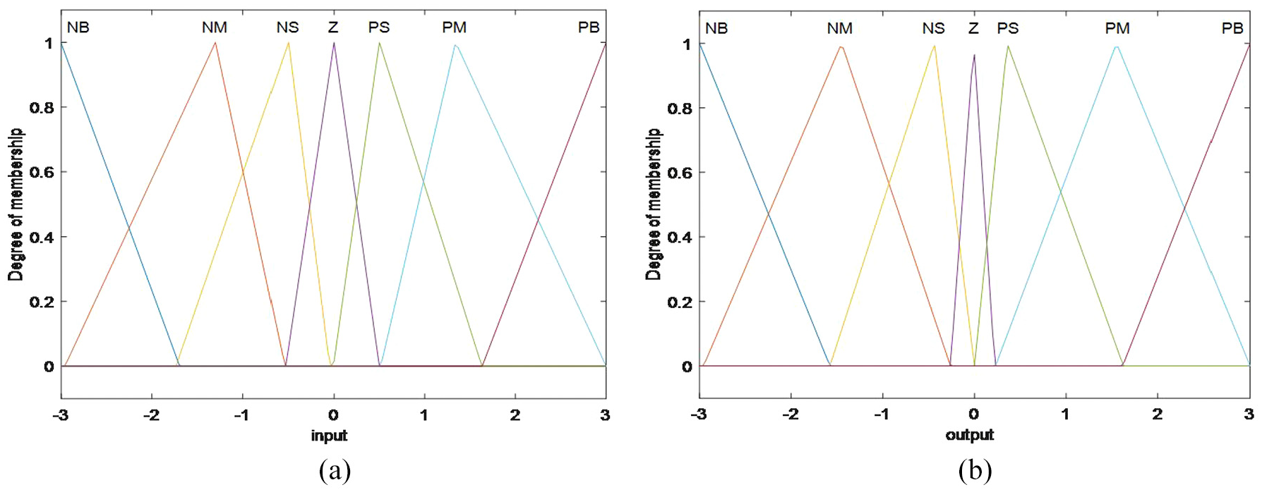
Fuzzy PID controller input and output membership function: (a) input membership function and (b) output membership function.
The membership function is characterized by sparse at both ends and dense in the middle, which is the characteristic of high-precision control. It can be adjusted quickly in case of large error and fine adjustment in case of small error.
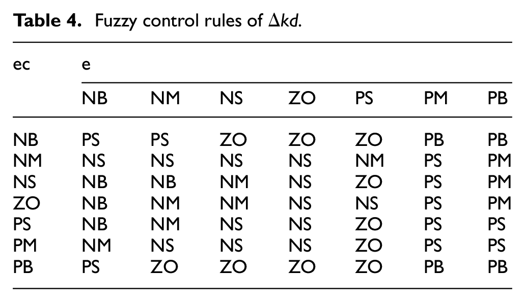
According to the analysis of the basic experience and skills of operators, the fuzzy control rule tables of
Fuzzy control rules of

Fuzzy control rules of
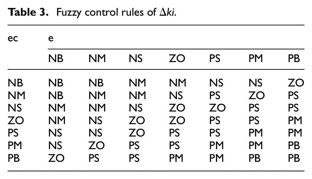
Fuzzy control rules of
Load force compensation model
The equivalent structure transfer function block diagram of electro-hydraulic position servo control system is shown in Figure 7.
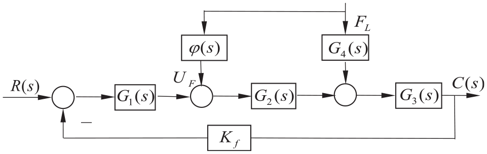
Transfer function block diagram of electro-hydraulic position servo system.
In the Figure 7,

Relationship curve between load force
It can be seen from Figure 8 that the relationship between the load force and the control quantity is approximately linear, and the relationship expression between the control quantity and the load force is obtained through curve fitting, that is, the calculation formula of the load force compensation is

Simulation results and analysis
In order to verify the effectiveness of the control method proposed in this paper, the basic principle block diagram of the control algorithm is built by using the Simulink toolbox of MATLAB, and then the joint simulation of MATLAB and Amesim is carried out. The selection of simulation parameters is consistent with Table 1. The simulation platform is used to compare the improved particle swarm compound control strategy proposed in this paper with ordinary particle swarm compound control and Fuzzy PID control.
The particle swarm algorithm first calls the Simulink model in Matlab, assigns the parameters of the three dimensions of the particle to
Parameters of improved particle swarm optimization algorithm.

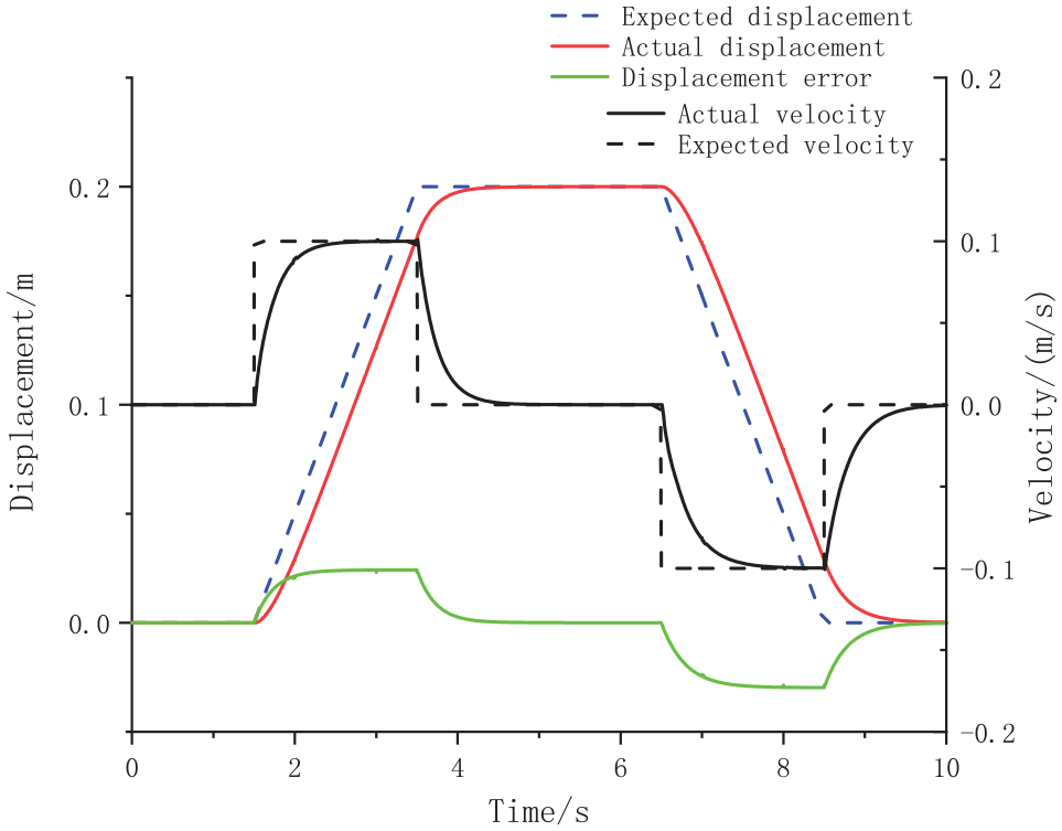
Figure 9 shows the simulation results of improved PSO compound control. The expected displacement is the slope signal. The piston rod extends according to the slope rising law, reaches 0.2 m, stops for 3 s, and retracts according to the slope law. From the simulation results in Figure 9, it can be seen that using the improved PSO compound control strategy proposed in this paper, the piston extension and retraction speeds are close to the expected speed of 0.1 m/s, and the adjustment time is 0.3 s. The displacement response curve basically coincides with the expected displacement curve. The dynamic error during forward and reverse motion is about 0.01 m, the steady-state error is zero, and the symmetry of forward and reverse motion is good.

Slope response simulation curve of improved PSO compound control.
On the premise of not changing the controller parameters, Figure 10 shows the ordinary PSO compound control. It can be seen that the deviation between the actual running speed and the expected speed is large, the actual displacement curve also lags behind the expected displacement, and there is obvious asymmetry in the forward and reverse motion. For comparison, Figure 11 shows the simulation results when the position is given as step signal and Fuzzy PID control is adopted. When only fuzzy PID control is adopted, and the given position signal is a step signal, there is a speed instantaneous impact, the running speed in the positive and negative directions is different, and its size cannot be controlled, and large pressure changes of the hydraulic system will be caused. The simulation results show that compared with ordinary PSO compound control and Fuzzy PID control, the hydraulic cylinder position control and speed control can obtain good control effects by using the control strategy proposed in this paper, which reflects the compensation effect of this control strategy in asymmetric hydraulic cylinder system.
Slope response simulation curve of ordinary PSO compound control.

Step response simulation curve of fuzzy PID control.
Fuzzy PID control
Experimental result
Finally, the improved PSO compound control strategy is verified on the platform of valve controlled asymmetric hydraulic cylinder system. The test system is mainly composed of active hydraulic cylinder, loading hydraulic cylinder, servo valve, hydraulic pump, pressure sensor, displacement/speed sensor, data acquisition, and computer control system. The upper computer adopts LabVIEW programming software. The experimental platform is shown in Figure 12.
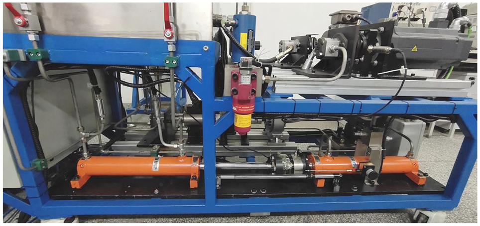
Experimental platform.
Figures 13 to 19 show the system responses with different control strategies under different input signals in the test. Compared with Figures 11 and 14, under the condition of no-load operation of the system, whether in the forward or reverse direction, the improved PSO compound control can obtain better control of speed and position without changing the controller parameters.

Slope response experimental curve of ordinary PSO compound control.

Slope response experimental curve of improved PSO compound control.

Ramp response at different speeds experimental curve of improved PSO compound control.

Experimental curve of system response under sinusoidal signal input (0.25 Hz).

Experimental curve of sinusoidal signal tracking error (0.25 Hz).

Experimental curve of system response under sinusoidal signal input (0.16 Hz).

Experimental curve of sinusoidal signal tracking error (0.1 Hz).
When the input is a ramp signal, the expected speed is 0.1 m/s. When the ordinary PSO compound control strategy is adopted, the steady-state error of speed is about 0.003 m/s, the system adjustment time is 1.2 seconds, the dynamic error of displacement is 0.03 m, and the steady-state error of displacement is 0.01 mm, as shown in Figure 13. When the improved PSO compound control strategy is adopted, the steady-state error of speed is 0.001 m/s, the system adjustment time is 0.5 s, the displacement dynamic error is 0.01 m, and the displacement steady-state error is zero, as shown in Figure 14.
As shown in Figure 15, when the expected speed becomes 0.08 m/s, it can be seen from the experimental results that the actual operating speed almost coincides with the expected speed in the steady state, and the system adjustment time is only 0.5 s, the actual displacement response curve basically coincides with the expected displacement curve, and the steady-state deviation is zero.
From the above experimental results, it can be seen that the improved PSO compound control proposed in this paper has excellent dynamic and static characteristics.
Figures 16 to 19 show the comparison of tracking sinusoidal signal between ordinary PSO composite control algorithm and improved PSO composite control algorithm.
It shows the compensation effect of the two algorithms in the asymmetric hydraulic cylinder system at different frequencies. If the input signal frequency is lower, the system will follow better and the error will be smaller. Under the same frequency, the improved PSO compound control has better follow-up and less error. The improved PSO compound controller proposed in this paper inherits the adaptability of Fuzzy PID controller to input changes, and has better tracking and compensation performance.
Figure 20 shows that the given speed is 100 mm/s, and the loading test is carried out at 4.5 s. The loads are 5, 8, and 12 MPa respectively. The piston speed of the hydraulic cylinder oscillates slightly with the load fluctuation, but soon recovers to stability. The displacement response curves under different loads basically coincide, and the steady-state position deviation is within 0.02 mm. Figure 21 is a partial enlarged view of system loading at 4.5 s. The speed fluctuates slightly with the load, but the adjustment time is only 0.02 s. Figure 22 shows the step loading force of the system, and the loading time is 1 s. It can be seen from Figures 20 and 21 that the improved PSO compound control has good control performance.

System response curve under loading.
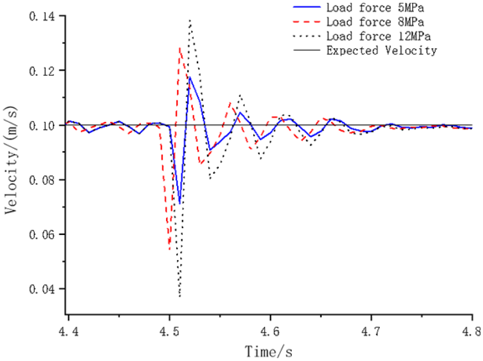
Partial enlarged view of system loading at 4.5 s.

Loading force curve.
Conclusion
In this paper, the asymmetric hydraulic servo system with large-scale load change is modeled and analyzed, and the specific transfer function is obtained. The crossover and mutation operations in genetic algorithm are introduced into particle swarm optimization algorithm. Aiming at the asymmetry caused by valve controlled asymmetric hydraulic cylinder, an improved PSO compound control strategy is proposed, which can adapt to large-scale changing load. At the same time, the control asymmetry of asymmetric hydraulic cylinder is compensated.
Using the proposed control strategy, the simultaneous control of speed and position is realized. Under different loads and different input follow signals, there is no need to adjust any parameters. Regardless of forward or reverse operation, the optimal dynamic performance and minimum steady-state error are obtained. The actual operation speed is basically the expected speed, and the position control accuracy is high. The effectiveness and superiority of the improved PSO algorithm are verified.
Footnotes
Handling Editor: Chenhui Liang
Declaration of conflicting interests
The author(s) declared no potential conflicts of interest with respect to the research, authorship, and/or publication of this article.
Funding
The author(s) disclosed receipt of the following financial support for the research, authorship, and/or publication of this article: The work of this paper is supported by the National Natural Science Foundation of China (No. 51675399).