
Abstract
The vehicle front-end module (FEM) is an integrated system in which major modules are assembled in the front of the vehicle. Among the FEM components, a carrier occupies the largest volume and weight. In recent years, the requirements of a carrier are increasing due to the diversification of vehicle size, enlargement of headlight, and so on. So, recent requirements are difficult to satisfy with the existing design. Therefore, this study was attempted to solve the current problems by applying only plastic, not the existing hybrid type, to the most important Member-radiator Support Upper (MRSU) of the carrier. As a process, topology optimization was performed using Altair’s Optistruct, thereby implementing a new concept of MRSU. In addition, the strength analysis was conducted using ABAQUS of Simulia. An initial model and an optimized model were compared and verified to determine the validity of optimization. After that, a prototype of carrier was manufactured and the final verification was conducted through HLR test. As a result, the strength and weight of the carrier were improved by about 24% and 15% respectively. In addition, the waste-generating process was improved, resulting in a development time reduction of approximately 32%.
Introduction
Major technology trends in the automotive industry have been dominated by electronics, battery development, and modularity research. In particular, a lot of research, time, and money are invested in modularization and many parts are modularized and applied to mass-produced cars. For example, there are suspension modules, door modules, driver modules, seat modules, and chassis modules.1–3
The FEM is an integrated system that contains various major vehicle modules, such as the cooling module, hood-latch (HL), head lamp, bumper beam (B/Beam), horn, and so on, which are assembled around a carrier, as shown in Figure 1.4,5 And, it can be modularized easily, and it has great advantages in terms of manufacturing, ease of maintenance, cost, and weight reduction. Because of these advantages, it has been applied to many vehicles.6,7

Structure of a front-end module (FEM).
The carrier is a major component of the FEM and is located at the front of the vehicle, as shown in Figure 2.

Carrier position for vehicles.
A few years ago, a carrier was designed by using only steel. But now a hybrid-type carrier with steel and plastic was developed according to the technology development of engineering plastic. Figure 3 shows a hybrid-type carrier that is being made in recent years, and presents the structure in which engineering plastic is injected on steel. According to the study of Fourcade et al., 8 this hybrid-type carrier has excellent in terms of NVH performance because it is possible to design robustness as well as weight loss and cost reduction.

Structure of a hybrid type carrier.
However, the importance of performances such as strength, weight, and cost reduction is increasing as requirements become more stricter due to diversification of vehicles and the enlargement of headlamp. For the reason, problems have been occurred continously. In particular, there were many performance failures on a member-radiator support upper (MRSU) during the hood-latch retention (HLR) test, as shown in Figure 4.

Photo of the damaged MRSU area.
The HLR test is a test to confirm the stiffness strength performance of the carrier by pulling the hood latch mounted on the carrier. The HLR test confirms the stiffness strength of the carrier by pulling the hood latch mounted on the carrier. It is a very important performance because it can lead to safety problems in which the hood of the vehicle opens while driving. It can lead to safety problems, as the hood of the vehicle opens while driving. Since, the hood-latch (HL) is made of a material with high strength, so its stiffness and strength depend on the carrier-MRSU part.
The requirements for the HLR test are as follows. A displacement should be lower than

Requirement of HLR test.
Because the result of the HLR test is dependent on the structure of the MRSU. Thus, iterative design process has been required to find a structure of MRSU that satisfies the requirements as shown in Figure 6. This design process creates a lot of waste.

Carrier design process.
If structural standardization of the MRSU were possible, these problems could be solved, but it cannot be standardized because there are many different factors, such as the stiffness, strength, location, design layout, and so on.
Therefore, this study was conducted to develop excellent carrier with price competitiveness in this situations where it is difficult to meet the requirements only with the existing empirical design. In other words, we dealt with a new concept MRSU design applied only with plastic, away from the conventional hybrid-type carrier.
A Research has been conducted to develop a new concept of MRSU that removes steel parts and uses only all plastics, rather than increasing steel parts in hybrid carriers to improve strength performance. So, topology optimization using Altair’s Optistruct (version 2017) was applied in the carrier. And then, the non-linear static analysis was conducted between an initial model and an optimal model by using a commercial structural analysis software ABAQUS from Simulia. Finally, the actual product of the optimized model was produced and the HLR test was implemented to verify. Also, a methodology to improve the time-consuming iterative design process is proposed throughout the study.
Topology optimization
The HLR test conditions have the highest failure rate among tests, and it is difficult to satisfy the requirements. Therefore, in order to satisfy the HLR test requirements, an analysis condition was implemented as a test condition. The specifications of the analysis condition are shown in Figure 7, and the design area is specified to proceed with topology optimization for the MRSU.

Analysis conditions for the optimization.
The formulation of stress-based topology optimization using Optistruct is shown in equation (1).9–13

where
MRSU is made up of PA6 + GF30% engineering plastic. The basic mechanical properties are shown in Table 1. The Stress-Strain curve of PA6 + GF30% by Lanxess is shown in Figure 8.16,17
Mechanical properties of PA6 + GF30%.


Norminal stress-norminal strain of PA6 + GF30%.
Stress failure criterion (

Non-linear static analysis conditions.
The applied load
For the analysis, Abaqus software (version 2018) was used. As a result of the analysis, failure occurs at a

Result of an original model.
In addition, by utilizing the load value of 80.0% ×

Stress contour of elastic model (
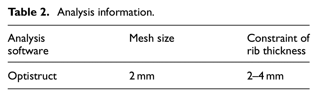
After then, topology optimization was conducted while considering rib conditions, spacing, and mold orientation with an option provided by Optistruct.18–20 Table 2 shows basic information about the topology optimization.
Analysis information.
Topology optimization refers to the process of utilizing density-based methods to determine the optimal layout of shapes, materials, and connectivity within a design domain. Density-based methods are used for determining whether to fill a volume within a given design area on the condition that the objective function is minimized.
After establishing the design region as shown in Figure 12(a), the low-density region is identified as shown in Figure 12(b) through a density-based method. The low-density regions are generated with voids to derive optimal solutions, as in Figure 12(c).21–25

Topology optimization: (a) design area and analysis conditions, (b) density-based method, and (c) optimization results.
The results of the optimization are shown in Figure 13 with the initial model, the optimization model, and the final model.

Comparison of initial model and topology optimization model.
In the case of the initial model, a truss structure was used to secure the stiffness and the strength. However, the optimization results show that ribs were produced in a continuous form with an arch-and-curve truss structure centered on the HL rather than straight-line ribs. Based on the results of the optimization, most of the derived positions and angles of the ribs were applied to the final model as shown in Figure 14. The model was made while considering the injection mold ability and life of the mold.

Final model with topology optimization.
Optimization design validation process
Computer aided engineering-based verification
In order to validate the topology optimization, the initial design and optimal design were validated. The comparison results of each model are shown in Figure 15.

Stiffness and strength analysis results: (a) comparison of force versus displacement, (b) original model, and (c) optimized model.
Figure 15(a) shows the displacements, and Figure 15(b) indicates the damaged area of the original model at about 80% of the requirements. Figure 15(c) shows that the result derived from the optimal model satisfies the requirements.
The weight and stiffness were improved by about 15.0% and 35.0% respectively, which are insignificant. In terms of the strength, MRSU fracture occurred in the initial design, while the strength derived from the optimal design satisfied the requirements, and we found that a sufficient strength reinforcement effect of approximately 60.0% was obtained over the initial design.
Test-based verification
To validate the performance, the optimized MRSU was created. The actual test is shown in Figure 16. First, it was fastened to a fixture that was assumed to be mounted on a vehicle. Then, after fastening a jig of a hood strike to the HL, the stiffness performance was verified by tensioning it to the required load as shown in Figure 17.

Optimized MRSU product.

Hood latch retention test.
Four test samples were used for this test, and the HLR test results are summarized in Table 3. As a result of the test, the displacement was lower than the required
HLR test results.

Conclusions
There have been many issues when designing carrier parts of a vehicle, which are major components of the FEM. Major issues are listed below:
The design is strongly dependent on the designer’s experience.
There have been wasted time and efforts during product development due to the repeated design procedures and analysis processes.
Because of these problems, it is not easy to design a lightweight carrier with sufficient strength performance. Therefore, in this study, topology optimization was applied to improve these problems, and the following conclusions and effectiveness were found.
(A) Through topology optimization, a shape in which arch shapes and X shapes are mixed was derived.
(B) It was found that the product weight was reduced by 15%, and the strength performance was improved by more than about 24% under the requirements.
(C) The design process time was improved by over 32.0% as shown in Table 4. A collaborative development process without repetitive work was constructed as shown in Figure 18.
Development-time comparison results.


Improved design process.
If the topology optimization is actively used in the initial concept stage of a product, it is judged that the initial design time can be shortened.
Footnotes
Appendix
Handling Editor: Chenhui Liang
Declaration of conflicting interests
The author(s) declared no potential conflicts of interest with respect to the research, authorship, and/or publication of this article.
Funding
The author(s) disclosed receipt of the following financial support for the research, authorship, and/or publication of this article: This research was supported by Yeungnam University Research Grant in 2021.