
Abstract
As for lightweight design of components, the multi-body dynamics analysis was conducted on the hydraulic power steering system with double front axles, and the load spectrum of the Steering Power Cylinder Bracket (SPCB) under typical working conditions was worked out. Then, the nonlinear strength calculation and topology optimization analysis of the bracket were carried out. According to the optimization results, the eight schemes were designed and the optimal one was selected according to the results of static strength calculation. Then the optimal scheme was subject to the analysis on fatigue strength. Finally, it was verified that the optimized structure was effective by means of the vehicle durability test. The results show that the weight of the SPCB is reduced by about 2.53 kg (the lightweight ratio of 43.2%) when such performance as stiffness and strength are greatly improved compared with that of original scheme. The lightweight effect is obvious and the optimization process can guide the lightweight design of similar parts.
Keywords
Introduction
Studies have shown that every 10% reduction in vehicle mass, fuel consumption can be reduced by 6%–8%, and exhaust emissions will be reduced by 5%–6%, which achieves the effect of energy saving and emission reduction and promotes the development of automobile lightweight to some extent. 1 At present, the main ways to achieve lightweight usually include structural optimization,2–9 new materials, 10 and new processes. 11 Among them, Liang et al. 2 optimized the structure of a gearbox under multiple load conditions, and the results showed that the mass of optimized gearbox was reduced by 7.6% compared with the initial model, the strength and stiffness were not weakened, and the first and second-order natural frequencies increased about 4.1% and 5.0%, respectively. Chang and Lee 3 optimized a compressor bracket, the mass of the optimized bracket was almost unchanged, the first-order frequency was raised above 29 Hz, and the averaged stress was decreased to 40% lower under the static load. Xiao et al. 4 designed a novel steel wheel with a 4.57% reduction in mass based on multi-objective topology optimization. Structural optimization is beneficial to save materials, and reduces the product cost to a certain extent, so it has been more widely used. However, the lightweight of components usually causes a decline in stiffness and strength, so it is necessary to use advanced optimization methods (such as topology, morphology, free size) and rigorous tests (virtual tests, bench tests, vehicle road tests) to ensure the quality of the optimization schemes, especially for some systems closely related to vehicle safety. The steering system realizes the function of changing the driving direction of the vehicle, and the design quality of its components directly affects the driving safety and lightweight level of the vehicle, which is concerned by the majority of scholars. Merkel and Schumacher 12 parameterized the key structural dimensions of a steering knuckle, and optimized the structure according to analysis results of CAE model automatically, which realized the goal of driving the initial design with finite element analysis results, and improved the speed and flexibility of structural optimization to a certain extent. Based on a vehicle, Krishna 13 took the minimum mass of steering knuckle as the optimization objective, took 36 shape parameters that had a great influence on the performance of the steering knuckle as variables, and took the stress value under different working conditions as constraint to carry out shape optimization, achieving a weight reduction of 12.7%. In order to increase the first-order natural frequency of a steering knuckle, Cheng et al. 14 adopted the compromise programming method to carry out topological optimization, and obtained the steering knuckle with lighter weight, higher natural frequency, and stronger stiffness. Nohara et al. 15 analyzed different finite element modeling methods of a steering knuckle, optimized the structure and shape of the steering knuckle according to the results of finite element analysis, and reduced the weight by about 9% successfully.
For heavy trucks with double front axles, the axle load is large, and the hydraulic power steering system is usually used. As an important part of the steering transmission mechanism, the Steering Power Cylinder Bracket (SPCB) assists the steering power cylinder to transfer its power to steering knuckles, so that the steering wheels can overcome the resistance moment of ground to achieve steering. It plays an equally important role as the other components of the steering system. Due to the large alternating load generated by the steering power cylinder, the SPCB is usually designed to be relatively heavy. Therefore, the continuous optimization of the bracket, so that it can meet the requirements of durability with a small mass, is conducive to the improvement of the lightweight level of components.
As for lightweight design of components, a SPCB was optimized by topological optimization technology, and according to the optimization results, the design and strength analysis of the eight schemes were carried out. Finally, the fatigue calculation and test of the selected scheme were carried out to verify the feasibility of the scheme.
Load calculation of the SPCB
Introduction of hydraulic power steering system
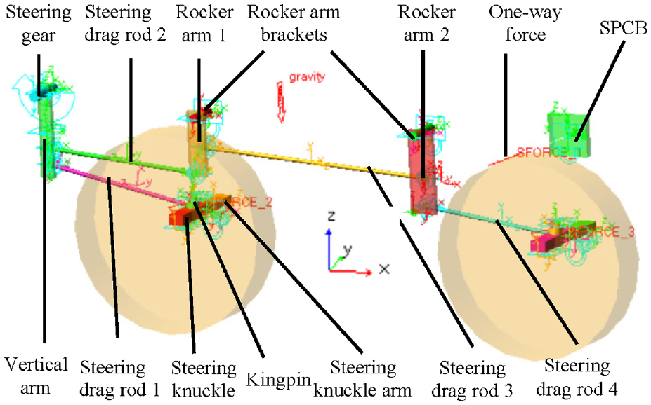
The hydraulic power cylinder is an important part of the hydraulic power steering system with double front axles, which helps the mechanical steering system to realize the steering of vehicle by hydraulic pressure. The hydraulic pressure comes from the hydraulic pump driven by the engine, and the assembly diagram of the transmission mechanism is shown in Figure 1. Among them, the steering drag rod 1 and the steering drag rod 4 are connected with the steering knuckle arms of the front axle 1 and the front axle 2 respectively through the ball hinges. The rocker arm brackets and the SPCB are fixed on the longitudinal beam of the frame. The upper end of the vertical arm is connected with the steering gear by spline. The rocker arm brackets are connected with the rocker arms through pins. The other parts are connected with ball hinges, such as the steering drag rods and the rocker arms, the steering power cylinder and the SPCB.

Steering transmission mechanism: (a) assembly drawing of the mechanism, (b) assembly diagram of the SPCB, and (c) A-direction view.
Calculation of loads
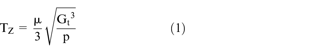
The force acting on each part of the steering system depends on the steering resistance moment of the wheel, which is composed of tire static steering resistance moment, return moment (gravity return moment, automatic return moment, lateral force return moment, longitudinal force return moment). When turning in place, it is necessary to overcome the friction torque between the ground and the tire, which is affected by many factors, such as tire pressure, front axle load, road friction characteristics, and so on. It is difficult to calculate accurately by the existing vehicle dynamic model, and it is usually calculated according to the empirical formula (1). When turning while driving, the friction between the tire and the ground changes from static to dynamic, the friction coefficient decreases and the steering resistance moment decreases. However, the return torque increases in a certain range with the increase of vehicle speed and wheel angle, and gradually becomes the main part of the resistance torque. Usually, the steering resistance moment of the wheel when driving is 1/2 to 1/3 of that when steering in place. Based on the common steering conditions of the vehicle and design specifications of the enterprise, the value of 1/3 is selected.
Where
In order to obtain the load curves of the SPCB in the steering process, the multi-body dynamics model was conducted on the hydraulic power steering system with double front axles by ADAMS software, as shown in Figure 2. When turning in place, the frame and I-beams of front axles don’t move relative to ground. So these parts are equivalent to the ground in the software. Therefore, the components fixed on the frame, such as steering gear, rocker arm brackets, and SPCB, were connected with the ground by fixed pairs. The kingpins fixed on the I-beams were connected with the ground by fixed pairs. The steering drag rods were connected with the vertical arm, rocker arms, and steering knuckle arms by ball hinges. Rotating pairs were established between rocker arms and rocker arm brackets, vertical arm and steering gear, steering knuckles and kingpins, wheels and steering knuckles, and a fixed pair was established between steering knuckle arm and steering knuckle. Then, a rotational motion of speed type was established on the rotating pair between the vertical arm and the steering gear, and the function IF (mod (time, 96) −32: −1 d, 0, 1−d) was used to drive the rotational motion. The function implements the following actions: (1) within the interval of (0, 32) seconds, the vertical arm rotates counterclockwise at the speed of 1 d/s to realize the right turning of the vehicle. (2) Within the interval of (32, 96) seconds, the vertical arm rotates clockwise at the angular speed of 1 d/s to realize the turning of steering wheels from the right limit position to the left limit position. (3) After 96 s, start again. A rotating pair was established between the steering knuckle and the kingpin, and the steering resistance moment was applied to the rotating pair, whose control function was IF (time-32: Tz, 0, IF (time-96: −Tz, 0, Tz)). The function implements the following actions: (1) In the interval of (0, 32) seconds, the steering resistance moment is Tz. (2) In the interval of (32, 96) seconds, the direction of steering resistance moment changes. (3) After more than 96 s, the direction of the steering resistance moment changes again. These ensure that the direction of the steering resistance moment is always opposite to the direction of steering. Because the steering power cylinder is equivalent to a two-force bar in this system, and its force is proportional to the output torque of the steering gear, the one-way force between the rocker arm 2 and the SPCB was used to simulate the power cylinder, and the output torque value (Ts) of the steering gear was constantly extracted to determine the force of the power cylinder. The control function of the one-way force was IF (time-32: Ts/334, 0, IF (time-96: Ts/270, 0, Ts/334)).
Multi-body dynamics model.
When the simulation time was set to 128 s, the whole steering process was realized and the load of each moving pair was output. The steering process was that the steering wheels started from the middle position, turned to the right limit position, then turned to the left limit position, and finally returned to the middle position. The load on the center of the ball hinge connected to the SPCB is shown in Figure 3. The load when driving is one third of that when parking, which is not listed here.

Load curves of the SPCB when parking: (a) X direction, (b) Y direction, (c) Z direction, and (d) force-Mag.
As can be seen from Figure 3, when the steering wheels turn to the right limit position, the load of the SPCB is the maximum, because the angle between the steering drag rods and the vertical arm is the smallest at this time, and the steering gear needs to output greater torque to overcome the steering resistance moment of the steering wheels.
Nonlinear strength calculation
Pretreatment
Because the load of the SPCB comes from the ball pin connected to it, and the mounting plane of the bracket is in contact with the longitudinal beam of the frame. The length of the ball pin and the stiffness of the longitudinal beam have a great influence on the stress distribution of the SPCB, so the calculation model should include the longitudinal beam, the SPCB, the ball pin, and their contact relations. Therefore nonlinear strength calculation is performed.
The geometric models of the longitudinal beam, the SPCB, and the ball pin were imported into the software. The longitudinal beam was meshed with 8 mm shell elements, 5 mm first-order tetrahedral elements were used to mesh the ball pin, and 3 mm hexahedral elements were used to mesh the SPCB. The number of elements was 23,170. After assigning attributes to the components above, the bolted connection was simulated by rigid and beam elements. The contact relationship between the bracket and the longitudinal beam was established, and the friction coefficient was 0.15. The “tie” type contact relationship was established between the ball pin and the hole of the SPCB.
Definition of working conditions
In order to obtain the performance of the SPCB in the steering process and facilitate multi-condition optimization, the steering process was discrete into multiple steering positions including the left limit, the middle position, the right limit and their uniform distribution, and the working conditions were defined respectively as shown in Figure 4: all the degrees of freedom of all nodes at the longitudinal beam section were restricted, and the loads were applied at the center of the ball pin. “STATIC” analysis method was used, and the “CONTROLS” keyword was defined in the analysis step to improve the convergence performance.

Finite element model of the SPCB.
Calculation result
The ABAQUS solver was used to obtain the stress nephograms of the SPCB under different working conditions. The stress value is the maximum at the right limit position of steering wheels, as shown in Figure 5.

Stress nephogram of the SPCB.
As can be seen from Figure 5, except for the high stress at the contact boundary, the maximum stress of the SPCB is 215 MPa, which is located at the inner rounded corner and the stress value is less than the yield strength of the material (ZG310-570). The stress value in most areas is small, and there is room for optimization.
Topology optimization
Principle and process of topology optimization
Topology optimization is usually used to optimize the material distribution of specific parts on the basis of the same assembly method. In other words, within a given load, constraint, performance index, and space, the optimal material distribution is found based on the mathematical optimal theory, so as to improve the material utilization rate. It has been viewed as one promising methodology. 16
The optimization took the minimum weighted compliance under multiple working conditions as the objective function, the relative density of each element in the optimized space as the design variable, and the upper volume fraction of the SPCB (0.2) and the structural symmetry as the constraint. The mathematical model can be expressed as follow:


Where m is the number of load conditions;
According to the principles above, the optimization work of the SPCB was carried out in accordance with the process shown in Figure 6.

Process of topology optimization.
Among them, the preparations before topology optimization calculation are as follows:
(1) Define optimized space: the space used for installing bolts and pins on the SPCB was defined as non-optimized space, and the remaining available space was defined as optimized space. The digital model is shown in Figure 7.
(2) Establish finite element model (FEM): imported the above digital model into HYPERMESH software to complete geometric cleaning, meshing, attribute, and working condition definition, in which the attributes of optimized space and non-optimized space should be defined respectively.
(3) Establish topology optimization model: on the basis of the above FEM, in the “topology” interface, the information such as optimized object, draft direction, and structural symmetry were defined. Then the “weighted comp” response was established, the weight coefficient was set in the response according to the frequency and harm degree of each working condition (in this paper, the weight coefficient of each working condition was equal), and set the minimum response (weighted comp) as the optimization goal by the “objective” button. Finally, the “volumefrac” response was established, and its upper limit (0.2) was set as the constraint by the “dconstraints” button.
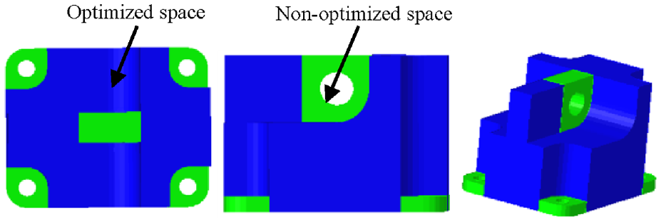
Optimized space definition model.
Topology optimization results
Submit the optimization model for calculation, and the optimization result when the threshold of relative density is 0.5 is shown in Figure 8.

Distribution of material density from different perspectives.
Structural reconstruction and schemes acceptance
Structural reconstruction
According to the optimization results, the designs of multi-round and multi-scheme were carried out, and the typical schemes are shown in Figures 9 to 11.

Design schemes of the first round: (a) scheme 1, (b) scheme 2, and (c) scheme 3.
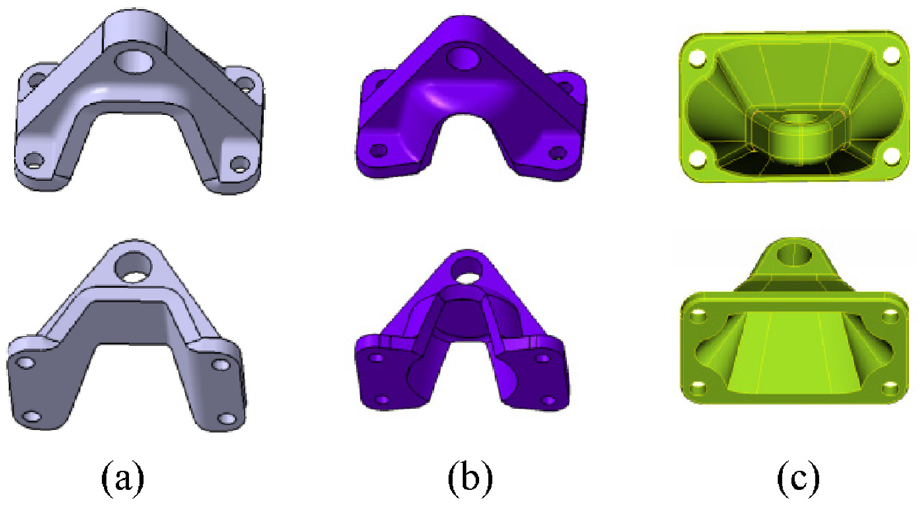
Design schemes of the second round: (a) scheme 4, (b) scheme 5, and (c) scheme 6.

Design schemes of the third round: (a) scheme 7 and (b) scheme 8.
Static strength calculation
The structural nonlinear calculation of the eight schemes above was carried out. When the steering wheels are located at the right limit position, the maximum stress of the SPCB and the displacement of the force loading position (ball pin center) are shown in Table 1.
Comparison of CAE calculation results between the optimized schemes and the original scheme.
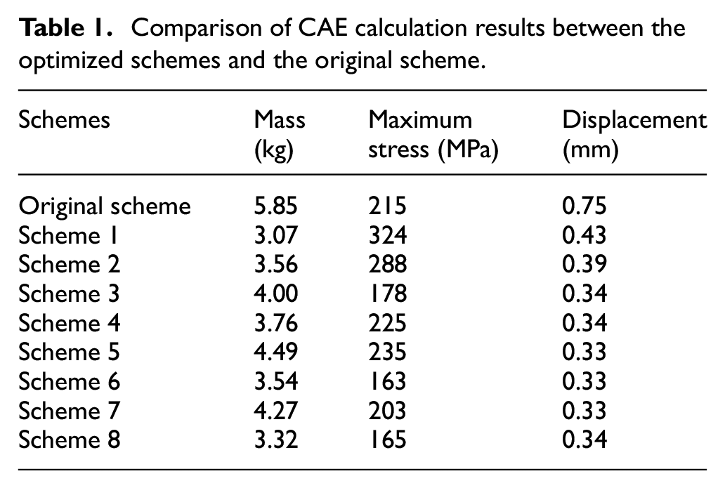
As can be seen from Table 1, the displacement of loading points of the new schemes is greatly reduced compared with the original scheme, because the new schemes increase the installation space of the four bolts, so that the supporting role of the longitudinal beam can be fully utilized. Among all schemes, the weight of scheme 8 is reduced by about 2.53 kg (the lightweight ratio of 43.2%) when such performance as stiffness and strength are greatly improved compared with that of original scheme. When the steering wheels are located at the right limit position, the stress and displacement nephograms of scheme 8 are shown in Figure 12.
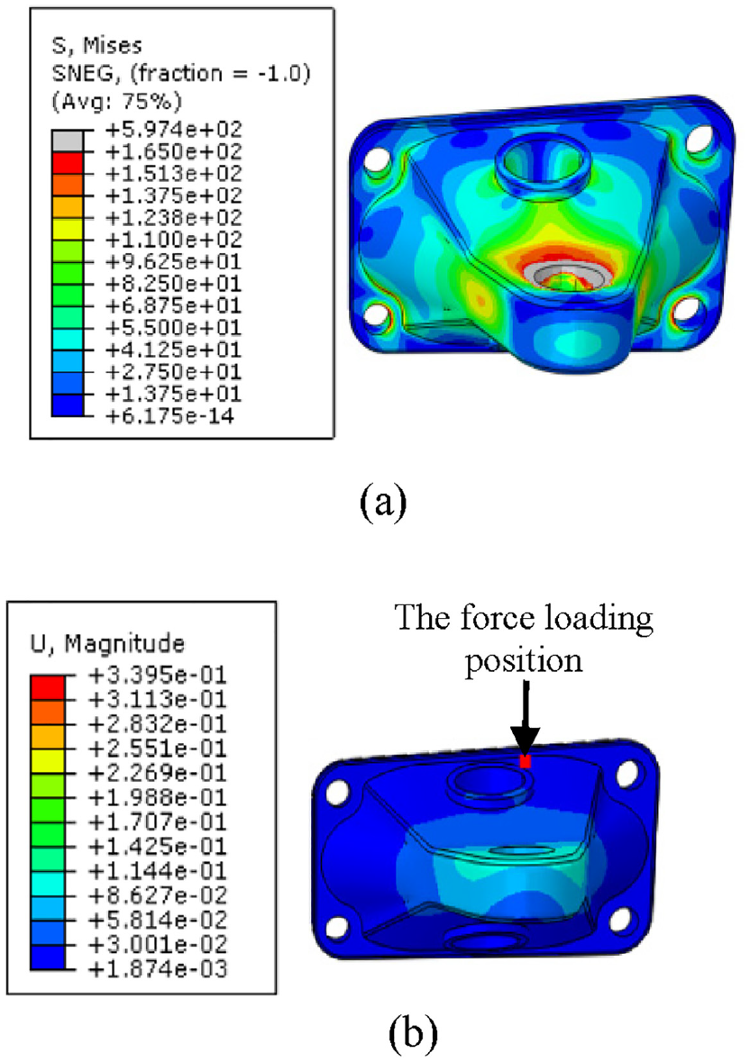
Stress and displacement nephograms of scheme 8: (a) stress nephogram and (b) displacement nephogram.
Fatigue strength calculation
The SPCB is usually subjected to alternating load, and fatigue failure is easy to occur under the condition that the stress is less than the yield strength of the material. Therefore, it is necessary to investigate its fatigue strength properties.
The components of steering system usually require a high fatigue life, and the fatigue failure belongs to high cycle fatigue, so the nominal stress method was used for calculation. In order to improve the accuracy of fatigue life prediction, fatigue samples were prepared according to GB/T 3075-2008 (as shown in Figure 13), and the fatigue life of the material (ZG310-570) was tested by lifting method. The S-N fitting curve at 50% survival rate is shown in Figure 14.
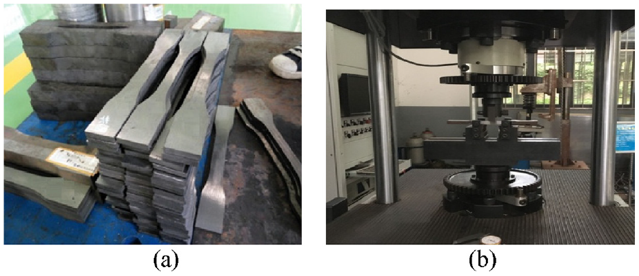
S-N curve test: (a) fatigue samples and (b) high-frequency fatigue testing machine.
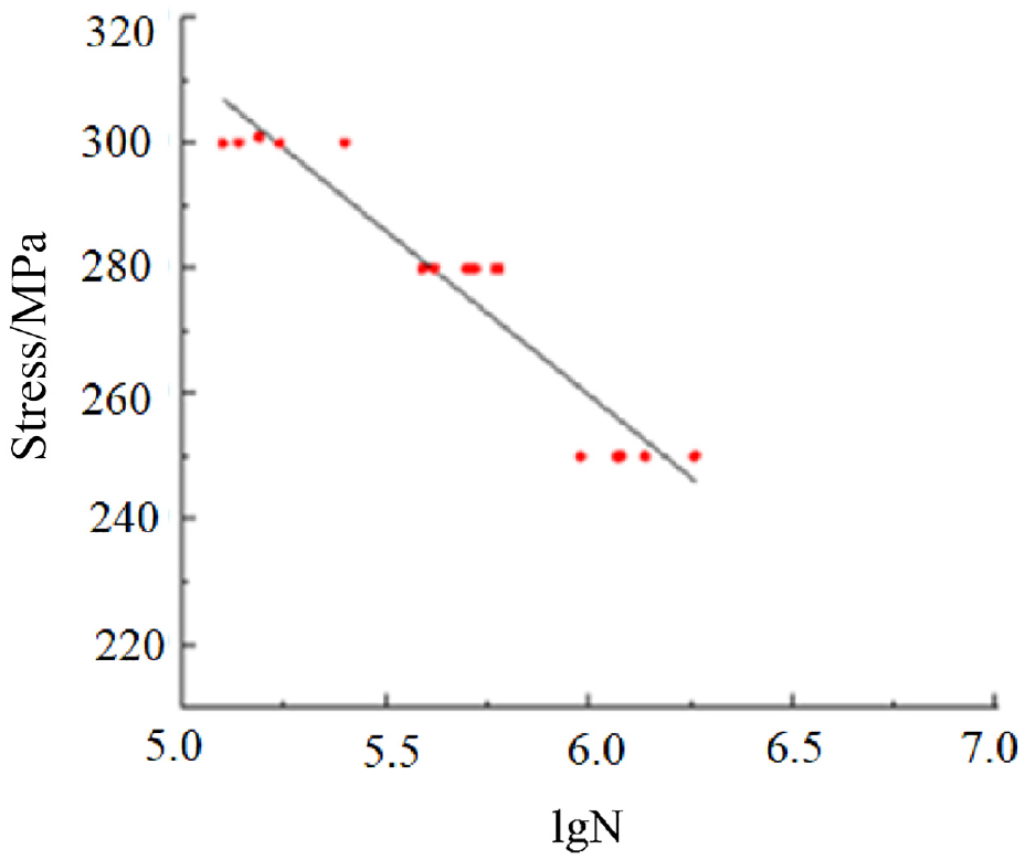
Test result of fatigue life.
N-Code software was used to establish the analysis model as shown in Figure 15, and the fatigue life of the bracket was calculated.

Fatigue analysis model.
The specific modeling process is as follows:
(1) In the static strength analysis model, the stress distribution results under the action of unit forces in X, Y, and Z directions were obtained respectively.
(2) The steering conditions of different vehicles are quite different. Considering the harsh working conditions such as steering while braking or going downhill and the importance of the components for safe driving, the parking and driving load spectrums were combined 1:1 as the load spectrum of the SPCB, as shown in Figure 16.
(3) The S-N curve of the material obtained by the test was given to the bracket, and the fatigue life was calculated by “Goodman” average stress correction and the calculation method combining the “CriticalPlane” and “Dirlik” methods.

The load spectrum of the SPCB.
The fatigue life nephograms of scheme 8 and original scheme are shown in Figure 17.

Fatigue life nephograms of the SPCB: (a) scheme 8 and (b) original scheme.
As can be seen from Figure 17, the minimum fatigue life of scheme 8 is 39,850, which is higher than that of the original scheme (10,782). And the original scheme is not destroyed during actual use.
Reliability and durability test
In order to test the reliability and durability of the SPCB under actual working conditions, it was assembled on the vehicle (as shown in Figure 18), the accelerated running test (40,000 km) and general reliability running test (1 million km) on vehicles were carried out according to GB/T12678-2021 (vehicle reliability running test method). The mileage distribution of various roads in the accelerated reliability test is shown in Table 2.
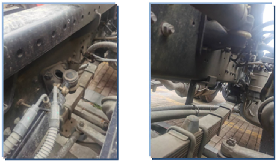
Scheme 8 assembly on the vehicle.
The mileage distribution of various roads in the accelerated reliability test.

The test results show that the SPCB is not damaged, and the failure information of the part is not found in the after-sales service information of the sold vehicles, which meets the operational requirements.
Conclusion
This article has completed the lightweight design of the SPCB under the guidance of topology optimization, and the project is summarized as follows:
(1) The dynamic analysis was carried out by the ADAMS model of the hydraulic power steering system with double front axles, and the load curves of the SPCB during parking and driving steering were obtained, which provided load for the analysis of dynamic and static strength.
(2) The nonlinear strength of the original SPCB was calculated by finite element method, and the stress distribution was obtained. Combined with the mechanical properties of its material, it was concluded that it was possible to reduce weight by optimizing the structure.
(3) The variable density topology optimization technology was used to optimize the SPCB, and eight typical schemes were designed according to the topology optimization results. According to the static strength calculation results of each scheme, the optimal scheme was selected, and the fatigue strength calculation of the SPCB, the accelerated and general reliability running tests of the vehicles equipped with the SPCB were carried out to verify the feasibility of the optimal scheme.
(4) By means of load calculation, topology optimization, structural reconstruction, performance calculation and test, a new type of SPCB with light weight and high durability was obtained: the weight was reduced by about 2.53 kg when such performance as stiffness and strength were greatly improved compared with that of original scheme, and the lightweight ratio reached 43.2%.
Footnotes
Handling Editor: Chenhui Liang
Declaration of conflicting interests
The authors declared no potential conflicts of interest with respect to the research, authorship, and/or publication of this article.
Funding
The author disclosed receipt of the following financial support for the research, authorship, and/or publication of this article: The research is supported by: “Qinglan Project” funding project of Jiangsu Colleges and universities; Research Project of professor or doctor in Wuxi Institute of Technology (10493121018).