
Abstract
Considering small diameter pipes, special pipes conveying corrosive, and flammable medium, a two-mass impact pipeline robot driven by a non-circular gear is proposed to study the walking dynamics of the robot in a dry piping environment. The mechanism principle of the two-mass impact pipeline robot is given to illustrate the walking mechanism of the robot under the combined action of the internal force and the external isotropic coulomb friction force. A dynamic model of a two-mass impact pipeline robot driven by non-circular gear is established. The dynamic response of the robot calculated by the numerical method reveals the walking characteristics of the pipe-impact robot under nonharmonic inertial force. The results show that the moving speed of the robot fluctuating rises with the increase of the input speed. The moving speed of the robot can be effectively improved by increasing the eccentricity of the non-circular gear or setting a certain amount of compression of the spring which is between the internal oscillator and the housing.
Introduction
The pipeline network is a significant infrastructure for water transmission, heating, communications, natural gas, petrochemical industry, and nuclear industry. 1 Pipeline robots play an important role in accurately performing a given task and ensuring human health and safety. 2 There are crawlers, legged, and wheeled robots with simple manipulation and high reliability in conventional pipeline systems. 3 But for special pipeline systems that convey corrosive, flammable media, or small diameter, more stringent requirements are imposed on the size, sealing, and corrosion resistance of the robots. Therefore, a smaller inertial pipeline robot with a fully sealed power system and no moving wheels/legs is more adaptable.
The inertial pipeline robot interacts with environmental friction through internal inertial force to produce unidirectional movement. Provatidis studied the mechanisms with two eccentrics that rotate in opposite directions and has proved the possibility of a linear motion driven by periodic inertial forces. 4 Furthermore, he installed the eccentric block driven by the motor on the floating object and reveals that the maximum distance of the floating object is proportional to the square root of motor speed. 5 Connecting two single-mass robots through elastic elements, etc. can form a two-unit single-mass robot. Zimmermann et al. 6 studied the linear motion of a two-element system connected by a spring on a rough plane and found that the average velocity could be controlled by changing the phase of the eccentric block. They used the averaging method to find an expression for the average velocity of a two-element system in a viscous damped medium. It is found that the average velocity of the robot depends on the asymmetry of the viscosity coefficient. 7 Akbarimajd and Sotoudeh 8 designed a small vibration-driven robot, the motion principle of the robot is analyzed and the corresponding mechanical parameters are given. Electronic derives are designed and the structure of the robot is optimized. Besides, Muscia 9 studied inertially driven underwater ships and found that the speed of the ship could be increased by using an elliptical gear shift to variable drive a mass that rotated against the center. As can be seen from the above research, the rotational speed law of the eccentric block has a significant influence on the mobile performance of the inertial robot. It is very beneficial not only to reduce the cost and volume of the inertial robot, but also to improve the moving speed of robot by using the non-circular gear to change the eccentric block speed without the servo sensor system.
The inertia force can also be excited by the reciprocating vibration of the mass block. Two single-mass with relative motion will form the simple two-mass movement system. Chernous’ko optimized the kinematic parameters of the two-mass movement system in the dry10–12 and viscous damping13,14 environments. Bolotnik and Figurina 15 proposed a three-mass system by installing two reciprocating internal masses in a rigid body. The movement speed of the system is improved through the coordination of two internal masses. Yegorov and Zakharova 16 optimized the motion parameters of the system in the damped medium, which can ensure the minimum energy loss during the system movement. Fang and Xu investigated the creep dynamics of a vibration-driven system from the perspective of sliding bifurcation. They obtained the approximate expression of the mean steady-state velocity by using the average method and improved the maximum mean steady-state velocity by parameter optimization.17–19 Also, they applied the averaging method and modal superposition to study the steady-state motion of the three-mass vibration-driven system. It is found that besides changing the friction coefficient, the efficiency of the system can be improved by changing the initial phase between the internal motions. 20 Chen and Xu 21 studied the dynamics of a new vibration-driven system with two-mass connected by a mechanical position limiter under isotropic dry friction. By connecting the elastic element, it can be driven by impact. Liu et al. studied a capsule system whose internal mass was driven by harmonic forces. He used four different friction models to describe the movement of the capsule system in different environments and obtain the maximum speed of the capsule robot.22,23 Liu et al. 24 designed an in-tube mobile robot that transforms inertial shock into displacement through the deformation of the piezoelectric double-layer membrane and simulated the dynamic response of the whole system. Liu and Liu 25 studied an asymmetric inertially driven robot, and carried out dynamic simulation and solution for the robot in horizontal and inclined pipes. These studies show that the two-mass system has more flexible speed control, which is conducive to improving the moving speed of the inertial robot. However, the reciprocating mass in the system needs to be controlled by a servo to achieve a specific motion law, which increases the system complexity.
In conclusion, using non-circular gear to modify the harmonic inertia force, using two-mass(multiple-mass), or using the impact force of the collision to drive can improve the mobility performance of the robot. The organic integration of these three methods will hopefully maximize the speed of the robot. Therefore, this paper proposes a two-mass impact pipeline robot driven by non-circular gear to construct a multi-mass nonlinear dynamics model of the robot. We analyzed the movement characteristics of the impact robot under the action of asymmetrical inertial force and the correlation law between the main parameters and the average movement speed. It provides the basis for designing the fast-moving impact pipeline robot.
Mechanism composition and traveling principle of two-mass impact pipeline robot
The two-mass impact robot consists of an internal oscillator, an impact plate, and a housing. Its three-dimensional diagram is shown in Figure 1. The vibration excitation mode of the internal oscillator is the key to the mobile performance of the robot. The characteristics of the two-mass impact robot proposed in this paper are as follows: the internal oscillator variable speed drives the eccentric block to generate anharmonic vibration through a non-circular gear. Thus, the mobile performance of the robot can be improved by using the special vibration mode and the impact between the internal oscillator and the impact plate.
Mechanism diagram of two-mass impact pipeline robot.
The mechanism principle of the two-mass pipeline robot is shown in Figure 1. The internal oscillator consists of the motor, non-circular gears, synchronous gears, and eccentric block. The motor drives the active non-circular gear 1, and the driven non-circular gear 2 is rigidly secured to synchronous gear 3. The centerline of the non-circular gear is parallel to the direction of the robot movement. The two synchronous circular gears 3 and 4 are the same geometric dimension, with the connecting line between their rotating center is perpendicular to the direction that the robot moves. Two identical eccentric blocks are respectively secured to the synchronous circular gear. The angle between the eccentric block and the non-circular gear is Δφ (i.e. the angle between the largest diameter of the driven non-circular gear and the eccentric block). The impact plate and internal oscillator are attached to the housing by a spring and damping. There are multiple rows of elastic supporting feet installed on the housing, which can cause pressure on the pipeline. Adjusting the pressure value can control the friction between the robot and the pipeline. Each row of supporting feet is evenly arranged along the circumferential direction of the pipeline to ensure the stable support of the robot, with generally no less than 3.
In the internal oscillator, the transmission ratio of the non-circular gear and the Angle Δφ between the eccentric block and the non-circular gear determines the vibration mode of the internal oscillator. When the motor rotates, the two eccentrics counterrotate under the drive of a synchronous circular gear, which generates the abnormal inertia force that changes periodically along the walking direction of the pipeline robot, and then stimulates the internal vibrator to produce non-harmonic vibration. The backlash between the internal oscillator and the impacting plate can be controlled to ensure impact. In the process of vibration, the impact force between the internal oscillator and the housing is far greater than the combined force of the spring and damping between them. Therefore, the internal oscillator has an opposite force on the housing, which interacts with the friction force of the pipeline inwall to make the robot move in one direction.
Mechanical model of two-mass impact pipeline robot
Transmission ratio of non-circular gear
The effect of the transmission ratio of non-circular gears on the mobile performance of the robot is important. The nonlinear angle relation between two non-circular-gears can gain by integrating the transmission ratio. However, for the commonly used closed non-circular gear, it is impossible to obtain the analytical expression of the rotation Angle relation between the driving and driven gears, such as elliptical, cochlear, and eccentric circular gears. What brings great inconvenience to the dynamics modeling and solving of the robot in this paper. Therefore, the method of constructing the transmission ratio of non-circular gear based on the Fourier series is adopted to obtain the analytical expression of the Angle relation. It is easy to satisfy the closure condition of the pitch curve of non-circular gear.
The polar Angle of the active non-circular gear is taken as the independent variable, the equations of the non-circular gear ratio function are constructed in the following form:
where i21 is the angular velocity ratio of the driven non-circular gear to the driving one. ω1 and ω2 are the angular velocities of the driving and driven non-circular gear. n1 and n2 are the orders of the driving and driven non-circular gear. φ1 is the polar angle of the driving non-circular gear. ij is the ratio of the order of the driven non-circular gear to that of the driving non-circular gear, with ij = n2/n1, in which n is the number of terms of the Fourier series. an and bn are the coefficients of each item. According to equation (1), the expressions of the rotation angle and radius vector of non-circular gears can be derived:
where r1 and r2 are the radius vector of the driving and driven non-circular gears, φ2 is the polar angle of driven non-circular gear, A is the center distance of two non-circular gears. When the non-circular gear rotates from a position where the polar Angle is zero, the rotation Angle of the non-circular gear is equal to the polar Angle. In the following descriptions, it is considered that the rotation angle and the polar angle of the non-circular gear are equal.
According to the definition of the intersecting angle Δφ between the driven non-circular gear and the eccentric, the expression of the phase angle of the eccentric can be obtained as follows:

As for inertial robots, the input angular velocity of the system is known, so the angle φ1 of the driving non-circular gear can be expressed as a linear function of time t. Through the expression of φ2 in equation (2), the expression of φ0 can be deduced with independent variable t. Then the kinematic model of eccentric can be expressed by analytical function, which is the basis of dynamical modeling for the inertial robot. That is the reason why the Fourier series is used to construct the transmission ratio of non-circular gear.
Dynamic equation
The robot moves horizontally, tilt, or even vertically in the pipeline. Let the Angle between the centerline of the pipeline and the ground be α, and the x-axis is parallel to the centerline of the pipeline, as shown in Figure 2. The eccentric block is simplified into a particle of m0/2 and a massless connecting rod of length R. In the x-axis direction, the displacements of the centroids of the eccentric block, the internal vibrator, and the housing are x0,x1, and x2 respectively. Let us represent the relationship between x0 and x1 are as follows:


Force analysis diagram of pipeline robot.
Taking the second derivative of x0 concerning t could resulting in the acceleration of eccentric block in x-direction as the following equation:

The force analysis of the eccentric block, the internal oscillator, and the housing is shown in Figure 2. Where F10(F01) is the force of the internal oscillator (eccentric block) on the eccentric block (internal oscillator) in the x-direction, F12(F21) is the force of the internal oscillator (housing) on the housing (internal oscillator) in the x-direction. Ff is the friction force between the pipeline and the robot. The force analysis of each component is shown in Figure 3.

Displacement curve of robot.
The two eccentric blocks rotate against each other, with the inertial forces in the y-direction balance. Then the differential equations of motion of the two eccentric blocks in the x-direction are as follows:

where g is the acceleration of gravity. According to the force analysis of the internal oscillator in Figure 2, the differential equation of motion of the internal oscillator in the x-direction can be obtained:

where F01 satisfy the equation as follows:

When x1 − x2 ≤ b, the internal mass will not impact the impacting plate, but when x1 − x2 > b, it will. Therefore, it can be represented that:
where, k1(k2) and c1(c2) are the spring stiffness and damping between the internal oscillator (impact plate) and the housing respectively. b is the gap between m1 and the impact plate when the spring is free. By combining equations (5)–(9), the dynamic equation of the internal oscillator can be obtained as follows:
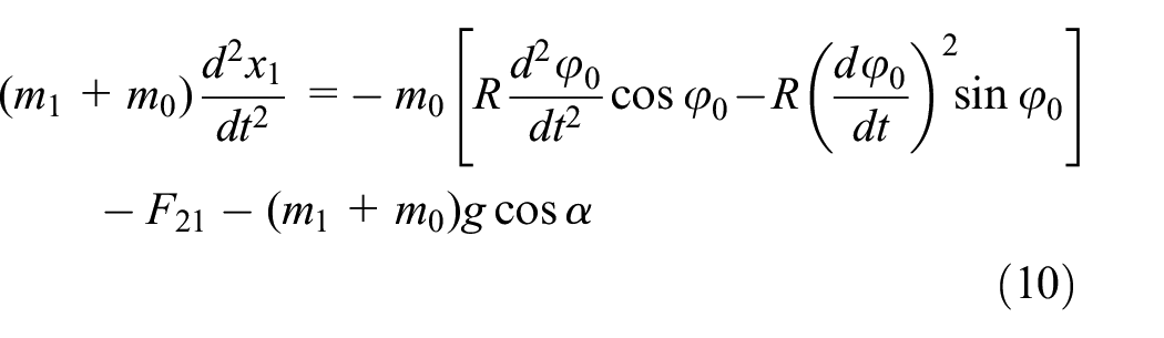
where φ0 is a function of time t.
According to the force analysis of the housing in Figure 2, the differential equation of motion of the housing can be obtained:

where F12 = F21 and Ff satisfies the following equation:

where μ and N are the sliding friction coefficient and supporting force between the elastic support foot and the pipeline inwall in Figure 3. All supporting feet remain in contact with the pipeline when the robot is moving. Therefore, the supporting force N is only controlled by the deformation of the elastic foot and is independent of the weight of the robot. Substituting equation (9) in equations (10) and (11), equations (10) and (11) are the two degrees-freedom dynamic models of the two-mass impact pipeline robot in Figure 1, in which the generalized coordinates are the displacement of the internal oscillator x1 and the displacement of the housing x2.
Simulation results and discussion
Based on the proposed dynamic model, the moving performance of the two-mass pipeline robot is simulated. The influence mechanism of the main parameters of the system on the mobile performance of the robot is revealed, which provides a theoretical basis for designing a fast-moving two-mass pipeline robot. Since the velocity of the pipeline robot changes periodically in the process of movement, the average velocity va in one cycle is used to evaluate the robot’s moving performance.
System parameters
The design parameters of the robot in the simulation analysis are shown in Table 1. The orders of the non-circular gears are 1. Let the transmission ratio function take only the first term of Fourier series, with b1 = 0, so the pitch curve of non-circular gear concerning polar axis symmetry can be obtained. When connected with the eccentric block, the centroid radius vector of the eccentric block is perpendicular to the axis of symmetry of the driven non-circular gear 2. This can make the eccentric block in the direction of the forward movement of the robot to stimulate the maximum inertia force. When the angle between the pipeline and the ground is greater than zero, it is thought to add a constant load caused by gravity to the robot, whose function is similar to that of wall friction. We make that α = 0 for discussing expediently.
System parameters of pipeline robot.

The dynamic equations (10) and (11) are solved by using MATLAB and numerical methods to obtain the dynamics response of the pipeline robot in Table 1. Figure 3 is the displacement curve of the pipeline robot. As you can see that the robot can realize one-way step movement, and there is a small amount of pauses phenomenon in each movement cycle. It can be seen from the velocity curve in Figure 4 that the robot’s velocity changes periodically. There is a zero value for velocity, so the robot pauses during each movement cycle. At this point, the average moving speed of the robot is 0.0456 m/s.

Velocity curve of robot.
Influence of system parameters on average speed
Moving speed is the key index to measure the performance of robots. For the impact pipeline robot, the average velocity va is used to evaluate its mobility performance because of its time-varying speed. Considering the limitations of the diameter of the pipe and the test equipment carried, the weight of the robot is generally immutable. According to the dynamic model of the two-mass pipeline impact robot, the parameters that affect the dynamic performance of the robot are mainly research speed n1, non-circular gear eccentricity a1, and impact clearance b. Therefore, this paper is devoted to the influence of motor speed n1, non-circular gear eccentricity a1, and impact clearance b on the robot’s moving speed through the control variable method.
Influence of motor speed on average speed of robot
Motor speed n1 increases from 100 to 3000 r/min and the average velocity va curve of the robot’s average velocity is obtained, as shown in Figure 5. When the motor speed is lower than 150 r/min, the average velocity va is 0, and the robot is stationary. When the motor speed increases from 150 to 690 r/min, the average speed of the robot increases first and then decreases. As the motor speed continues to increase, the moving speed of the robot increases first and then decreases in the range of the motor speed from 690 to 1329 r/min, 1329 to 1968 r/min, and 1968 to 2565 r/min, but the maximum average velocity va in each interval increases with the motor speed n1.
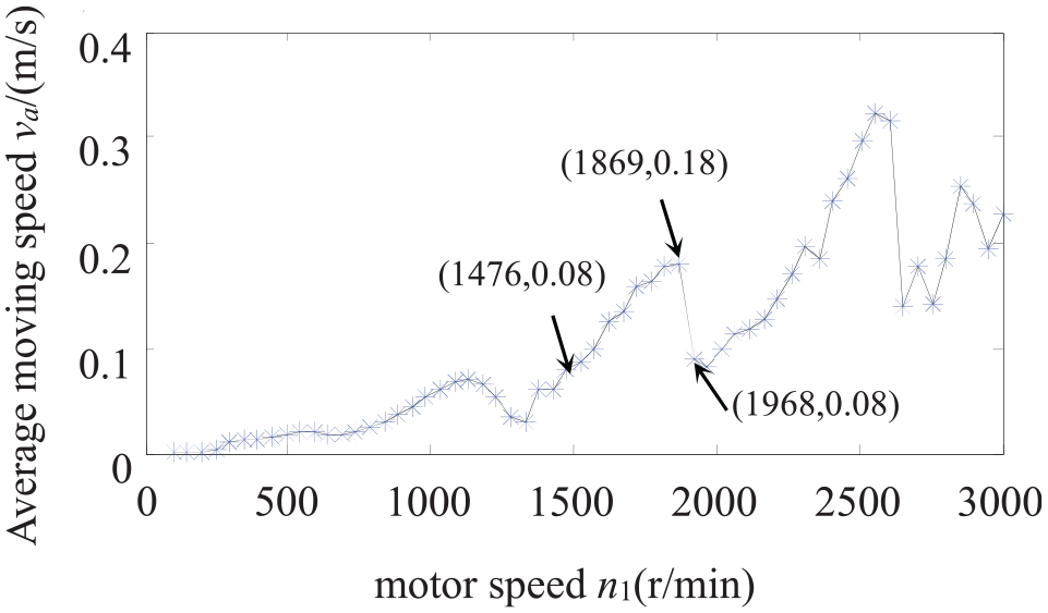
The influence of motor speed on average moving speed of robot.
In the interval 1329–1968 r/min, the three special values indicated by the arrow in Figure 5 are taken. When the motor speed n1 is 1476, 1869, and 1968 r/min, the relative motion phase diagrams of the internal oscillator and the housing and the forces between them are calculated respectively, as shown in Figures 6 and 7. Figure 6 shows the relative motion phase diagram of the internal oscillator and the housing at different rotating speeds. When the relative displacement is positive, they are in contact. Otherwise, it means that the two are separated. At different rotational speeds, the internal oscillator will impact with the housing. The relative motions of the two vibrators are approximately periodic when the motor speed n1 is 1476 and 1869 r/min, while the relative motions of the two vibrators are aperiodic when the motor speed n1 is 1968 r/min.

Phase diagram of relative motion at different n1: (a) n1 = 1476 r/min, (b) n1 = 1869 r/min, and (c) n1 = 1968 r/min.

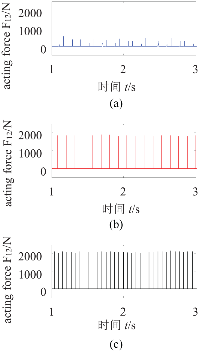
Relative forces at different n1: (a) n1 = 1476 r/min, (b) n1 = 1869 r/min, and (c) n1 = 1968 r/min.
Figure 7 shows the force of the internal oscillator on the housing. Because the impact time is short and the impact force is far greater than the force of spring and damping between the internal oscillator and the housing, the F12 curve presents pulsation characteristics. In approximately periodic motion, both the impact force and frequency (the number of impacts per unit time) of the internal oscillator to the housing increase as the motor speed increases from 1476 to 1869 r/min. Since the impact force is the driving force generated by the robot housing to overcome the external friction, the average moving velocity va of the robot increases with the increase of the motor speed n1. When the motor speed n1 increases to 1968 r/min, the internal oscillator vibrates aperiodicity relative to the housing. At this time, both the impact force and the number of impacts decrease to different degrees. As a result, the moving speed of the robot decreases. It can be concluded that some particular rotating speeds cause the internal oscillator to vibrate aperiodic relative to the housing, which leads to the reduction of the impact force and the number of collisions, and the robot speed decreases further.
Figure 8 shows the displacement curves of the robot at three rotational speeds. When the relative motion of the internal oscillator and the housing is approximately periodic. The local fluctuation of the displacement curve is ignored, and the displacement of the robot has linear characteristics on the whole. The displacement of the robot is nonlinear in general when the relative movement between the internal oscillator and housing is aperiodic. At this point, the calculated average velocity va of the robot is related to the integral time. Therefore, in Figure 5, when the input speed exceeds 2565 r/min, there are big fluctuations of the average speed of the robot, which is caused by the nonlinear displacement of the robot.

Displacement curve at different n1.
As can be seen from the above analysis, the average velocity va of the impact pipeline robot rises in a fluctuating manner with the increase of the motor speed. In a determined velocity range, the average velocity va increases first and then decreases with the increase of the motor speed n1. This indicates that a larger motor speed can improve the average moving speed of the robot on the whole. But a continuous increase in motor speed may lead to a decrease in the impact force and the number of collisions due to aperiodic vibration, thus leading to a decrease in the mobile performance of the robot. Therefore, the motor speed should be appropriately increased in a reasonable range when the robot moving speed is increased.
Influence of eccentricity on average speed of robot
Eccentricity a1 controls the range of transmission ratio variation of non-circular gear. When the eccentricity a1 is 0, the non-circular gear becomes a circular gear. With the increase of the eccentricity a1, the range of transmission ratio of non-circular gear increases. With the increase of the eccentricity a1, the range of transmission ratio of non-circular gear increases. At the same time, the local radius of curvature of the non-circular gear pitch curve decreases, which leads to undercutting or machining difficulties. Considering the actual machining of non-circular gears, the eccentricity a1 changes from 0 to 0.7. Other parameters in Table 1 remain unchanged, and the variation curve of the average moving speed of the robot with the eccentricity a1 is obtained, as shown in Figure 9.

Influence of non-circular gear eccentricity on average moving speed of robot.
When a1 increases from 0 to 0.7, the average velocity va of the robot increases from 0.045 to 0.084 m/s, and the average velocity va is nearly doubled. As can be seen that the non-circular gear variable speed is beneficial to improve the moving speed of the robot. We take the eccentricity a1 of the non-circular gear as 0 and 0.3, calculate the force between the internal oscillator and the housing. As shown in Figure 10, with the increase of a1, the impact frequency between the internal oscillator and the housing does not change, but the mean impact force increases from 1684 to 1892 N. Because of the variable speed rotation of the eccentric increases the inertia force, which strengthens the vibration of the internal oscillator. The impact force between the internal oscillator and the housing is improved, thus increasing the moving speed of the robot.

Relative forces under different a1 conditions:(a) a1 = 0 and (b) a1 = 0.3.
Figure 11 shows the displacement curves of the robot under two eccentricities. The displacement of the robot is linear on the whole. When the eccentricity a1 is 0.3, the mobile performance of the robot is better. As can be seen from Figure 10, this is due to the improvement of impact force. The non-circular gears can improve the mobility of the robot better than circular gears. Therefore, in the design of non-circular gear eccentricity ratio should be as large as possible.

Robot displacement curves under different a1 conditions.
Influence of clearance on average speed of robot
The clearance between the internal oscillator and the housing has a significant influence on the impact force. When b is positive, it represents the clearance between the internal oscillator and the housing at the initial position (the internal oscillator is in static equilibrium). When b is negative, it represents the compression of the connecting spring between the internal oscillator and the housing at the initial position. b increases from −20 to 10 mm, the average moving speed of the robot is shown in Figure 12. When the initial position clearance increases from 0 to 4 mm, the movement speed of the robot decreases from 0.05 to 0 m/s. As we can see that with the increase of the clearance, the moving speed of the robot decreases. When the clearance exceeds a definite value, the robot cannot move. By comparing the change curves of F12 when b = 0 and b = 3 mm in Figure 13, it can be seen that the increase of clearance will reduce the amplitude and frequency of impact force at the same time. The impact force is the driving force for the robot to move, so the movement speed of the robot is reduced. When the clearance continues to increase until the maximum amplitude of the internal oscillator is exceeded, there will be no more impact inside the robots. The external friction force cannot be overcome only by the spring and damping force between the housing and the internal oscillator, which causes the robot to be unable to move.

Influence of clearance on the average moving speed of the robot.
Relative forces at different b: (a) b = 3 mm, (b) b = 0, and (c) b = −6 mm.
It can also be seen from Figure 13 that when b decreases from 0 to −9 mm, the average moving speed of the robot decreases slightly from 0.053 m/s, and then increases substantially to 0.152 m/s, and the speed increases by nearly three times. As can be seen by comparing the change curve of F12 when b = 0 and b = −6 mm in Figure 13, when we give a certain amount of compression to the connecting spring between the internal oscillator and the housing, the impact force does not change significantly. But it will dramatically increase the frequency of impact, which improves the moving speed of the robot. When the b further decreases from −6 to −20 mm, av fluctuates several times, but they are all less than the value at b = −6 mm. When the compression of the connecting spring is large, the vibration excited by the internal oscillator has a certain inhibition.
Figure 14 shows the displacement curves of the robot under three kinds of clearance. The displacement of the robot is linear on the whole. It can be seen from the figure that when the connecting spring is compressed, it can effectively improve the mobile performance of the robot. When the spring clearance is −6 mm, the speed of the robot’s forward frequency is improved. Therefore, making the connecting spring between the internal oscillator and the housing keeps a certain amount of compression in the initial position, which can make the two-mass impact robot obtain the maximum impact force.

Robot displacement curves under different b conditions.
Walking test of two-mass impact pipeline robot
Robot design parameters
Based on the design principle of the fastest running speed at α=0 and the comprehensive consideration of the manufacturing difficulty of the physical system. The design parameters of the robot are selected according to the analysis results of dynamic characteristics, as shown in Table 2. Figure 15 shows an elliptical gear solid model, Figure 16 is the three-dimensional diagram of the internal mechanism of the pipeline robot, Figure 17 shows the experimental prototype manufactured.
Experimental parameters of pipeline robot.


Solid model of elliptical gear pair.

Three-dimensional diagram of internal mechanism of pipeline robot: (a) robot assembly main view, (b) robot assembly top view, (c) upward view of robot assembly, (d) side view of robot assembly shaft, (e) robot assembly left view, and (f) robot assembly left view.

Pipeline robot prototype.
Test results and analysis
The robot walks in a test tube made of plexiglass. The friction coefficient between the robot and pipeline inwall is 0.15. The pipe length is 1 m, and the test walking length is 0.8 m. The walking time of the robot can be obtained after the test process is shot by a high-speed camera. Then the average walking speed of the robot is calculated, as shown in Figure 18.
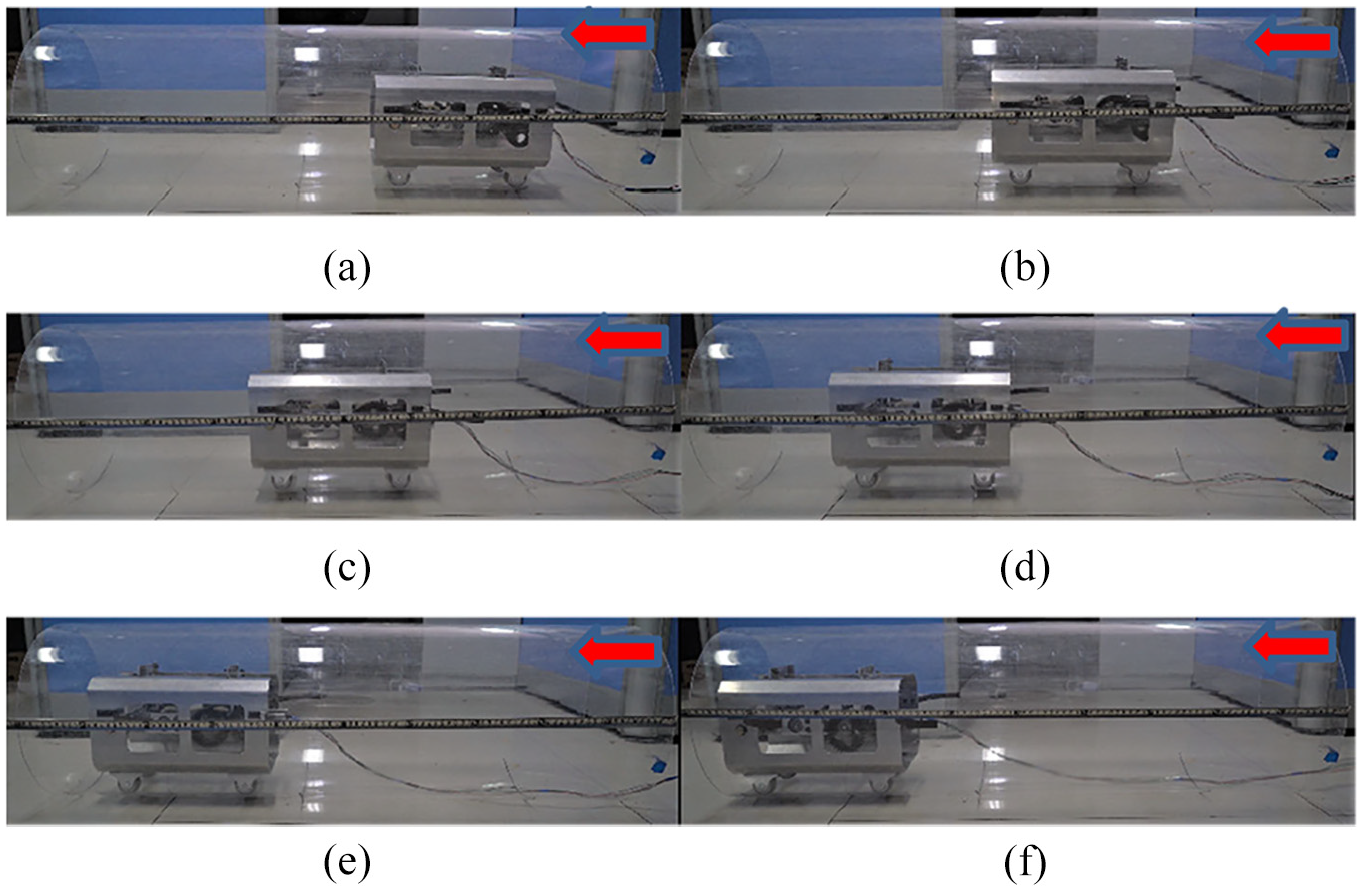
Pipeline robot walking test: (a) t = 0 s, (b) t = 2.85 s, (c) t = 5.71 s, (d) t = 11.42 s, (e) t = 14.28 s, and (f) t = 17.14 s.
By observing the walking process of the robot, it is found that the robot moves forward by stepping. The eccentric block collides with the impact plate once every rotation, and the robot takes a step forward without backward movement. The progressive characteristics are basically consistent with the theoretical displacement curve in Figure 19. The feasibility and the rationality of dynamic analysis of two-mass inertial pipeline robots excited by non-circular gear are verified.

Robot displacement curve at 160 r/min motor speed.
The average walking speed of robot the is further analyzed. The average walking speed of six groups of robots at different speeds was tested through speed regulation, and compared with the theoretical calculation results, as shown in Table 3.
Walking test of two-mass impact pipeline robot driven by non-circular gear.

As shown in Figure 20. “*” represents the theoretical average speed, and “+” represents the experimental average speed. As can be seen from Figure 18, both the theoretical average velocity and the experimental average velocity increase with the increase of the rotational speed in the range of 100–150 r/min. The overall change trend of the two is consistent, but the experimental value fluctuates up and down the theoretical value. The main reasons for this problem are as follows:
There are some errors in the manufacturing process and prototype assembly process;
There are some errors in the selection of friction coefficient between elastic support and tube wall.

Comparison of theoretical and experimental average velocities.
Conclusion
A two-mass impact pipeline robot driven by non-circular gears is proposed. It moves in one direction by internal asymmetric inertial excitation system and impact effects.
A two-degree of freedom dynamics model of the two-mass pipeline impact robot in a dry pipeline environment is established. In order to study the moving law of the robot, the dynamic characteristics of the robot are analyzed.
With the increase of the motor input speed n1, the robot’s moving speed rises in a fluctuation pattern on the whole. The moving speed of the robot increases with the increase of the eccentricity of the non-circular gear a1, while decreases with the increase of the clearance b. Therefore, in order to improve the mobile performance of the robot, it is necessary to properly value it.
The two-mass impact pipeline robot can be used to transport corrosion, flammable medium, or small diameter of the pipeline system. Inertial drive robot has the characteristics of completely closed power system, simple movement principle, and high structural reliability. It is more suitable for narrow, corrosive, inflammable, and explosive pipe environment.
Footnotes
Handling Editor: Chenhui Liang
Declaration of conflicting interests
The author(s) declared no potential conflicts of interest with respect to the research, authorship, and/or publication of this article.
Funding
The author(s) disclosed receipt of the following financial support for the research, authorship, and/or publication of this article: This research has been supported by the Hebei Province Graduate Innovation Funding (item number: CXZZSS2021057).