
Abstract
Higher than anticipated supersonic starting loads in the VTI T-38 wind tunnel were a consequence of higher than designed minimum start pressures. Initially, high starting loads limited the usefulness of the facility at high supersonic Mach numbers. Over time, it was established that several procedures and techniques had to be used cooperatively to diminish the problem. One of the techniques is the establishment of additional points of contact of the model and the support sting for the duration of the starting loads, so that a part of the aerodynamic loads is transferred to the sting through the added path, relieving the sensitive force balance. Some applications of this technique require dedicated mechanisms to operate, which was impractical for the VTI T-38 wind tunnel. To the contrary, the implementation of the idea in the VTI T-38 wind tunnel relies on using suitable inserts to make the clearance between the model and the sting such that model-sting contact is forced to occur during the start and stop phenomena, but not during the measurement phase of the test. For typical model configurations, transient starting and stopping loads can be reduced by more than 50%.
Introduction
Appearance of transient starting and stopping loads is one of the major problems in supersonic and hypersonic wind tunnels, and it can be particularly pronounced in blowdown wind tunnels with high operating pressures. During the start and the breakdown of the supersonic flow in a wind tunnel, randomly formed shock waves pass through the test section, and cause large local variations of pressure and flow direction. During these periods, the model, the measurement devices and the model support mechanism are subjected to transient aerodynamic loads that may be several times greater than loads in the established supersonic flow. Nature of the supersonic starting loads is dynamic, oscillatory, with varying amplitude and direction.
Supersonic starting loads can cause very high stresses in the tested model, the internal force balance and the support sting. If the balance is designed to withstand large transient loads, the actual, usually much smaller, steady-state aerodynamic forces and moments are measured with degraded sensitivity and accuracy. To tackle this problem, different methodologies and techniques have been devised and applied with more or less success.
The first group of techniques involves attempts to reduce transient loads acting on the model. In order to achieve that goal, some early designs of high speed wind tunnels incorporated mechanisms such as proximity plates, clamshells or rapid-insertion supports. 1 For example, a pair of proximity plates is placed by a suitable mechanism near the opposite sides of the model during the flow startup, thereafter retracted into test section walls and brought back into position during the flow unstart. 2 These designs are still in use in some facilities. However, such bulky mechanisms inevitably bring irregularities on test section walls, resulting in degraded flow quality due to generated undesirable shock waves. 3
Transient starting loads can also be reduced by reducing the minimum flow-start pressure of a wind tunnel, because the starting loads are usually proportional to it. This can be achieved to some degree by using a second throat or ejectors in the diffuser of the wind tunnel.
Another technique of reducing transient loads acting on the model has been attempted more recently, and it incorporates modifications of the wind tunnel start and unstart procedures. 4 As the transient loads typically increase with Mach number and stagnation pressure, the problem is alleviated by gradually increasing, when starting a wind tunnel, the supersonic Mach number and stagnation pressure of the flow in the test section. At the end of the wind tunnel test, Mach number and stagnation pressure are gradually decreased. The technique involves continuous change of the nozzle contour synchronously with increasing/decreasing stagnation pressure during the wind tunnel start/unstart. However, this methodology has never been applied in a blowdown wind tunnel due to predicted tendencies of stagnation pressure building-up during transition 5 and appears to be more suitable for a continuous supersonic wind tunnel.
The second group of techniques implies accepting the transient phenomena as they are and applying different solutions to protect the force balance, while the model and the support structure are still exposed to excessive starting and stopping loads. Since the balance is usually the most fragile part of the test setup, significant improvements in test safety and feasibility are expected to be achieved. The main idea is to fix the model on the support sting during the flow starting and stopping process, so that at least a part of the transient aerodynamic loads is transferred from the model to the support system by an alternate path, and not through the balance. Several designs appeared to implement this idea.
A patented design 6 proposes an inflatable jacket between the rear part of the wind tunnel model and the support sting. During the flow starting or stopping process, the jacket is inflated and fixes the model on the sting, relieving the force balance. However, this solution does not appear feasible in wind tunnels with high dynamic pressure, where the load capacity of the inflatable jacket would have to be up to several thousand Newtons, requiring a driving pressure of at least 50–100 bar applied through a small-diameter manifold within a sting – and yet, the device would have to be able to extend and retract in a fraction of a second.
Another patented design 7 proposes a conical insert moved along a sting by a pair of hydraulic cylinders mounted on the rear part of the sting. During the transient phenomena, the insert is located at the base of the model, while it is retracted downstream of the model during the steady-flow part of the test. The main drawback of this design is a bulky assembly of hydraulic actuators which would be difficult to streamline and install sufficiently downstream of the model in order not to affect the base flow. In addition, the operation in the conditions of significant sting and model deflections may be questionable and, in the case of changed clearance between the model and the sting, the sliding insert may hit the model and impart undesired axial overload on the force balance.
A design similar to Zilberman et al. 7 is the grounding mechanism 8 that comprises a taper lock which is driven into a matching taper at the base of the model by rods connected to a motor located in a protective housing on the downstream end of the support sting. When the flow starts, the mechanism is locked into the model in order to transfer the transient loads directly to the sting. The taper lock is then retracted for the duration of the steady-state part of the run and locked again before the flow stops.
The common drawback of most designs is that they would need a controller to monitor the flow conditions in the test section and rapidly deploy the devices not only during the controlled start or stop of a wind tunnel run, but also in the case of a flow breakdown, which could occur unexpectedly at any time because of some emergency situation. This is probably the reason why some of them do not seem to have been actually implemented in wind tunnel installations.
When the T-38 trisonic blowdown wind tunnel 9 of the Military Technical Institute (VTI) was built, it was noted that supersonic starting loads were unexpectedly high, which was caused by the minimum operating pressures being above the design values, probably because of an oversized silencer in the exhaust of the wind tunnel (although similar design under-estimates of minimum operating pressure were noted in other wind tunnels, too 10 ). Investigation of this problem began during the commissioning of the facility. It was gradually established that the starting loads problem could not be resolved by a single solution and that several procedures and techniques had to be used cooperatively. This paper presents a technique of forced model-sting contact, that was devised for partially relieving the balance during the wind tunnel start and unstart in supersonic tests. Contrary to previously mentioned implementations of the same concept, the application of the technique in the VTI T-38 wind tunnel does not require complicated controlled mechanisms to operate. Although the presented solution cannot be used in all test configurations, it has proved very useful for typical slender models.
Prediction of transient loads
Flow in the test section of a supersonic wind tunnel during the flow starting or stopping processes is very different from the established supersonic flow at test Mach number, which is demonstrated in Figure 1 showing flow patterns in the test section around a model, recorded using the schlieren visualization technique during the flow start process (a) and during the established supersonic flow at Mach 4 (b). The snapshot of the flow patterns during the established supersonic flow shows a uniform flow field in the test section, with a typical symmetric pattern of attached conical shock waves originating from model nose. The snapshot of the flow patterns during the flow start process shows strong oblique shock waves passing through the test section above the model. Attached conical shock wave can be observed on the lower side of model nose only, indicating asymmetric establishment of the supersonic flow and large changes of flow direction. Large pressure difference, and hence high loads, caused by these phenomena, resulted in a large angular deflection of the model-balance-sting assembly, which is visible in the pitch plane.
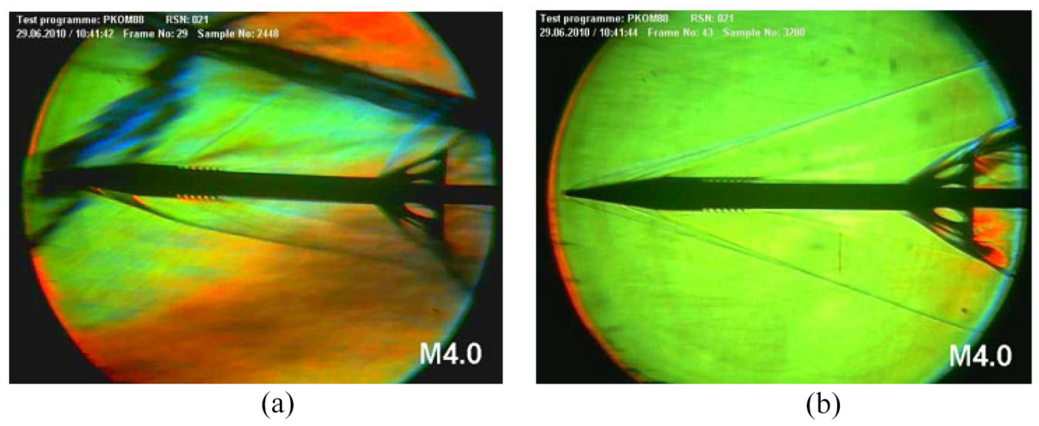
Three-color schlieren visualization: (a) transient shock waves in the test section of the VTI T-38 wind tunnel around a test model 11 during the starting of the flow at Mach 4 and (b) steady flow at Mach 4.
On the basis of the testing experience in the VTI T-38 wind tunnel, the amplitudes of aerodynamic forces on wind tunnel models during the starting of a supersonic flow are similar to steady-flow loads for the same models at angles of attack of about 30°–40°, but starting pitching, yawing and rolling moments can be several times larger than moments at steady supersonic flow conditions. Starting pitching and yawing moments also depend on the model form factor and can be very large for slender models. Moreover, because of their stochastic nature, starting loads can differ between identical wind tunnel runs, even as much as a factor of two.
It is obviously of interest to be able to predict the magnitude and character of the seemingly random supersonic transient loads before an actual wind tunnel test, in order to ensure model safety and select a proper force balance. Several theoretical models were developed over the years in an attempt to solve this problem, either assuming a normal shock wave passing over one side of the wind tunnel model1,12 or assuming that the model is at high angles of attack in the deflected flow behind an oblique or a conical shock wave located in the test section. 13 Some other load-prediction models rely on empirical estimates valid only for a particular wind tunnel installation.14–16
The magnitude of supersonic starting loads in a wind tunnel depends mostly on Mach number and stagnation pressure during the establishment or breakdown of the supersonic flow. The normal shock theory 1 and the modified normal shock theory 12 compute the starting normal-force loads FZT as a function of the wind tunnel flow-starting stagnation pressure P0start, projected area SZ of model contour in the direction of the load, and the starting-loads coefficient CS, as :

Pope and Goin 1 and Maydew 12 theories predict different values for CS. Pope and Goin 1 theory assumes a normal shock followed by subsonic flow existing on one side of the model only. Maydew 12 theory modifies this approach by taking into account the ratio of the area of lifting surfaces to total projected area SZ, so that models with smaller lifting or control surfaces should experience smaller starting loads. From VTI experience,14,15 Pope and Goin 1 theory estimates well the axial loads but overestimates the normal and side loads, for which Maydew 12 gives better results. Both theories neglect the occurrence of large pitching and yawing starting moments, which, in VTI practice, pose the main problem for an internal wind tunnel balance in the tested model. Therefore, a slight modification of a different approach devised by Boeing 16 was adopted in VTI as more convenient. P0start and CS are combined into “starting-loads pressure differentials”kX…kN pertaining to six force and moment components FXT…MZT of starting loads. Starting moments are related to model length L and wingspan B in the relations used to estimate the starting loads on typical models:

These loads are assumed to be dynamic (oscillatory) forces and moments acting at the centroids of model contour areas SX, SY, and SZ projected in the directions of the respective load components.
Magnitude of supersonic starting loads in the VTI T-38 wind tunnel
The dependence of starting loads on the stagnation pressure at the time of establishing or breakdown of the supersonic flow is very relevant for blowdown wind tunnels in which the supersonic flow is started at high stagnation pressures. The magnitude of starting loads in the VTI T-38 wind tunnel initially seemed unexpectedly high, but, when normalized by the experimentally determined flow-starting and flow-stopping pressures, which were higher than theoretical, it showed to be similar to other wind tunnels. The experiments also showed that the minimum stagnation pressure required to start the supersonic flow in the VTI T-38 wind tunnel was significantly higher than the pressure at which the supersonic flow broke down at the end of a wind tunnel run. At that time, an attempt was made to reduce the starting pressure by the application of a second throat, 14 which was not a part of the initial wind tunnel design. Second throat proved to be moderately effective (e.g. minimum-start pressure at Mach 4 was reduced from 14.2 to 12.4 bar, with a proportional decrease of starting loads, while minimum-stop pressure was not affected) and its use became a standard procedure for supersonic tests in this wind tunnel.
Over time, data on starting loads were collected from a number of supersonic wind tunnel tests in the VTI T-38. It was established that simple load-predictiontheories1,12,13 were not adequate, at least in the T-38 environment, and that the pressure-differential approach based on the method 16 used by Boeing provided better load prediction. Suitable values of pressure differentials kX…kN (2) were determined empirically (Figure 2) as upper envelopes of starting-loads recorded mostly on rocket and missile models which were the configurations most often tested at high Mach numbers in the VTI T-38.
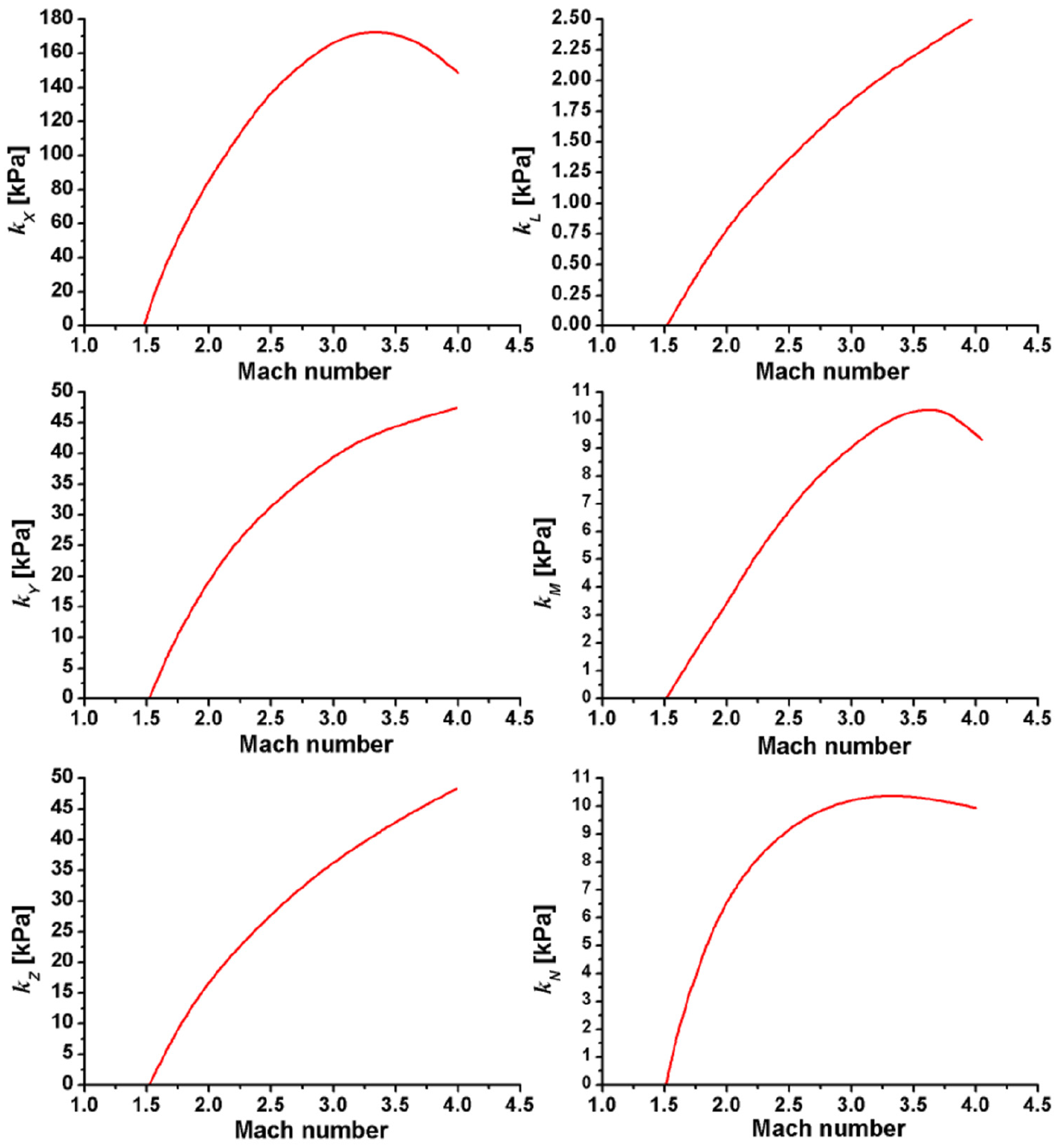
Empirically determined pressure differentials for the prediction of starting loads in the VTI T-38 wind tunnel.
The collected data showed that transient loads during the stopping of the supersonic flow were typically larger and longer-lasting than transients during the starting of the flow, which agrees with observations from other wind tunnels. However, loads in the lateral plane were typically larger than loads in the vertical plane, contrary to observances in another wind tunnel. 3
From the ratios of the values of kM versus kZ and kN versus kY in Figure 2 it can be deduced that the maximum starting pitching and yawing moments correspond to longitudinal shifts of acting points of the starting normal and side forces within approximately ±L/4 from the areas centroids, which is significantly more than the shift of the center of pressure of a typical supersonic model during moderate changes of the angle of attack. Therefore, the pitching and yawing moments can be the dominant and most critical components of supersonic starting loads, especially on long models.
As an illustration, a plot of a typical unfiltered output from the normal-force component of an internal wind tunnel balance recorded in a Mach 2.25 wind tunnel run is given in Figure 3. It can be observed that transient loads exceed maximum test loads by more than a factor of 2.

Plot of a typical unfiltered output from the normal-force component of an internal wind tunnel balance in a Mach 2.25 supersonic wind tunnel run.
Technique of forced model-sting contact
Contrary to other model-sting-locking proposals like Bryan 6 , Zilberman et al., 7 and Dionisio and Stockenstrom, 8 a simple technique, used in the VTI T-38 wind tunnel for relieving the internal wind tunnel balances of large pitching and yawing starting moments in supersonic runs, does not contain any controlling mechanisms that can act too slowly or fail. Also, it requires very little additional effort in the preparation of a test. The technique relies on the fact that, in the high-dynamic-pressure environment of the VTI T-38 wind tunnel, deflections of the force balance and the support sting under aerodynamic loads are relatively large. Assuming that the starting loads significantly exceed the steady-flow test loads and cause correspondingly larger deflections of the balance and the sting, the technique is based on deliberately allowing model-sting contact during the starting loads (which may seem counter-intuitive). When contact occurs, part of the aerodynamic load is transferred from the model directly to the sting, bypassing the sensitive wind tunnel balance. Whenever it is practical, test setup is arranged so that model-sting clearance at model base is sufficient (with some reserve) to allow for balance/sting deflections in a steady-flow supersonic test, but small enough for model-sting contact to occur when large starting moments cause larger deflections. The clearance is set by a cylindrical ring or jacket around the sting inside the base of the model (Figure 4). The ring is placed as far as possible from the balance center which, if permitted by other constraints, should be positioned in the model slightly forward of the centroids of projected areas SY and SZ. Besides, provisions are made for electric detection of model-sting contact on the inset ring, to check that it does not occur during the wind-on measurements but that it does occur during the starting and stopping of the supersonic flow.

Schematics of two variants of inserts used to adjust model-sting clearances (proportions not to scale).
The difficulty with this technique lies in the correct estimation of the optimum model-sting clearance so that an appropriate contact ring can be produced. Maximum loads expected in supersonic flow, increased by a certain safety factor (about 20%), but not exceeding permitted wind tunnel balance loads, are the basis for estimating the necessary clearance. If a monolithic wind tunnel balance is to be used, the deflections of the balance-sting assembly can be determined using finite-element analysis, but that approach may not be practical for assembled balances of unknown internal design. In such cases a calibration of the model-balance-sting assembly with respect to model-sting clearance versus expected aerodynamic loads may be needed before a test. The calibration is performed by applying dead-weights loads to a simulated or actual rear end of the model mounted on the balance-sting assembly. Also, to obtain the desired effects, it may sometimes be necessary to adjust the model-sting clearance during a test by changing the diameter of the contact ring. Therefore, it is convenient to design the contact ring so that it can be easily installed and removed, if possible without dismantling a model already mounted on a sting (Figure 5). Another drawback is that the technique relieves the balance only of the pitching and yawing starting moments, but not of the starting rolling moment loads and force loads. It should be noted that only the balance is unloaded in this way, but not the model and the sting. Besides, the technique cannot be applied in tests at high angles of attack (more than approximately 20°) because the aerodynamic loads and sting deflections at high angles of attack are similar to those during the starting and stopping transients. However, in high-angle-of-attack tests the load range of the force balance must be high as well, so that the possibility of starting loads exceeding balance capacity is diminished.

Model-sting-contact ring on the base of a HB-2 reference model.
The technique of forced model-sting contact was verified in wind tunnel tests of a missile with wrap-around fins (Figure 6). Length of the missile model was 1270 mm and the diameter of the model was 70 mm. It was mounted on a 48 mm dia. tail sting using a 2-in Able MkXXI six component balance, with the normal force load range of 31,150 N (at zero pitching moment), side force load range of 13,344 N (at zero yawing moment), axial force load range of 1780 N, pitching moment load range of 2875 Nm (at zero normal force), yawing moment load range of 1020 Nm (at zero side force) and rolling moment load range of 450 Nm. Tests showed that, by using the forced model sting contact, transient pitching and yawing moments on a balance could be reduced by more than 50%. Force loads on the balance were somewhat increased, which was far less important than the large reduction of moments. Results of the technique-verification tests are presented in Figure 6, normalized by relevant model areas and lengths, according to equation (2) and shown as equivalent starting-loads pressure differentials.
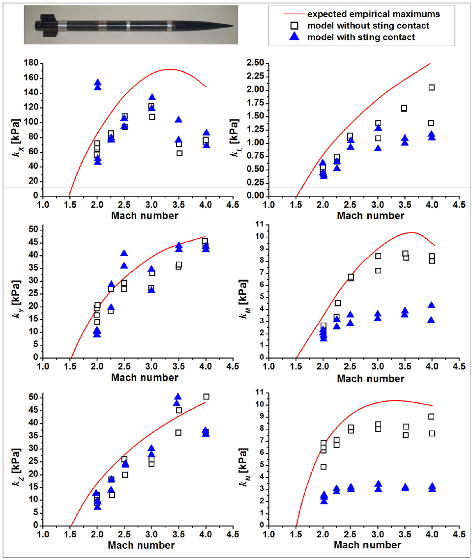
Reduction of the normalized starting loads, expressed as pressure differentials, on a six-component balance in a missile model by means of forced model-sting contact. Curves represent empirically estimated upper envelopes of starting-loads pressure differential. Symbols represent experimentally determined values.
The presented technique is used, whenever possible, in supersonic tests in the VTI T-38 wind tunnel. However, it should be emphasized that this is not a universal remedy for the starting loads, and the sting-contact technique is applied in VTI cooperatively with a number of other measures 15 in order to alleviate the starting-loads problem as much as possible.
Application of the forced model-sting contact technique
Wind tunnel test of a supersonic projectile model with a length slightly over 1500 mm and a diameter of about 56 mm was performed at Mach numbers up to 2.5. Preliminary analysis of test feasibility was done on the basis of prediction of aerodynamic characteristics. Also, transient loads expected in the supersonic test of this model in the T-38 wind tunnel were estimated according to equation (2) and Figure 2.
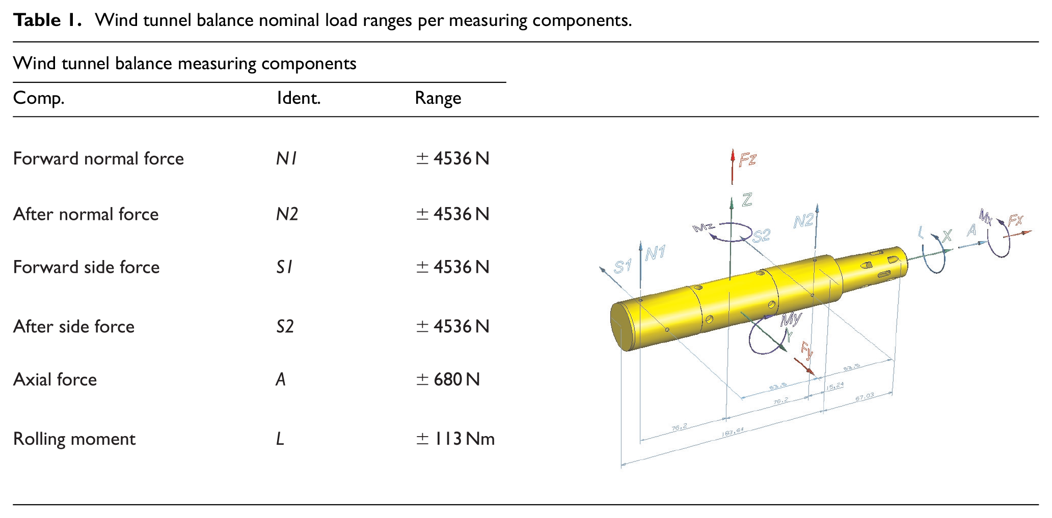
Analysis showed that, with respect to overall dimensions and load capacity, the six-component Able MkXV balance of 38.1 mm (1.5 in) diameter was adequate to be used in measurements of forces and moments for this model. Able MkXV is an assembled balance (i.e. consisting of several assembled pieces), of the design known as the force balance. 17 A balance of this type has two components measuring the normal forces, two components measuring the side forces, one component measuring the axial force and one component measuring the rolling moment. Nominal load range of the balance was 9072 N for the total normal and side forces at zero pitching and yawing moments, 678 Nm for the total pitching moment at zero normal force, 565 Nm for the total yawing moment at zero side force, 680 N for the axial force and 113 Nm for the rolling moment.
The balance nominal designed load ranges per measuring components are given in Table 1. The maximum permitted loads from the so-called loads rhombus, that is for maximum normal and side forces moments have to be zero and vice versa. Maximum simultaneous loads of measuring components are approximately 50% of the maximum design loads, when the four normal- and side-force measuring elements in the balance are actually loaded to 100% of their designed load capacity, Table 2. Calibration of the balance showed that it was operational within the expected accuracy margins; the accuracy obtained in the calibration was about 0.1% for all components.
Wind tunnel balance nominal load ranges per measuring components.

Wind tunnel balance nominal load ranges per components of total aerodynamic load.

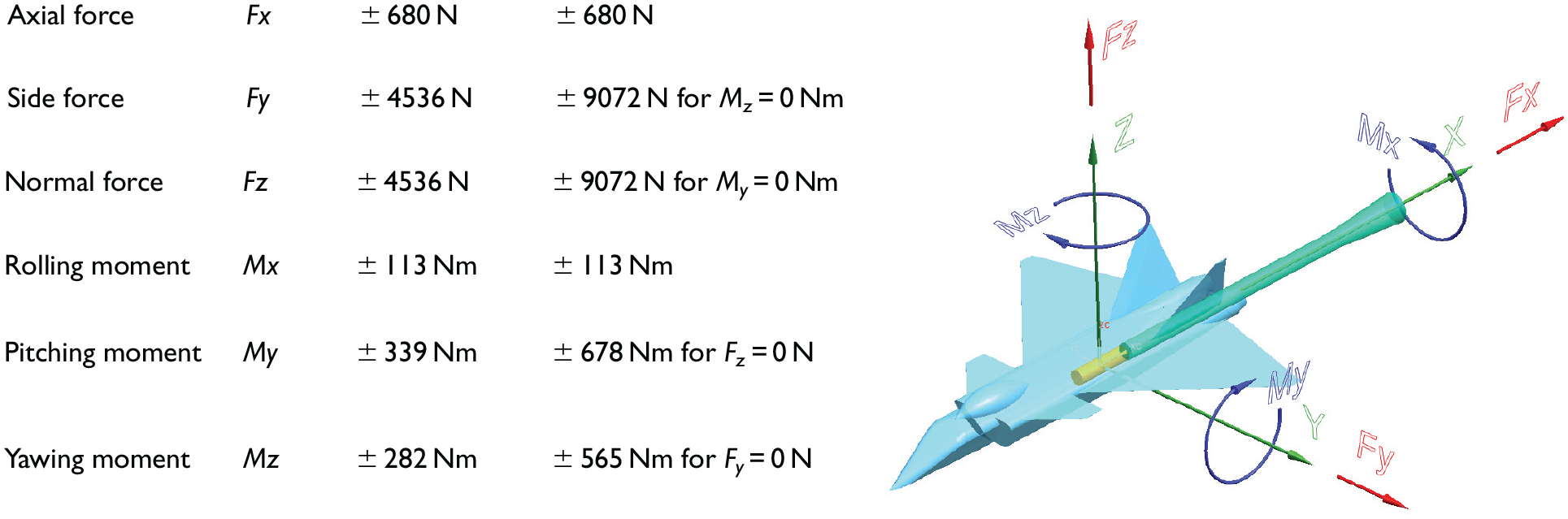
The analysis also showed that the possibility of testing at Mach numbers higher then 2 for the projectile model could be questionable as the predicted transient loads were somewhat higher than nominal load ranges of the selected balance. Applied prediction method was not precise enough to define with confidence whether starting loads would overload the balance. It was suggested to start the test while carefully monitoring the loads during transient phenomena. In order to better utilize the available load range of the balance with respect to transient loads which were expected to be higher in the yaw plane, it was rotated for −90° in roll as the balance load range with respect to moment loads was higher in the normal forces measuring plane (Figure 7). Therefore, the balance was applied so that its normal force components measured side loads and vice versa.

Able MkXV wind tunnel balance rotated for −90°; Measuring components are designated.
In order to be able to monitor the occurrence of contact of the rear part of the model and the sting at conditions of high aerodynamic loads, a simple sensor was installed on the sting inside the rear part of the model, at the location where the clearance between the model and the sting was smallest (about 4 mm). The sting that was used had a 42 mm diameter at the front end with a conical transition to a 32 mm diameter. From model geometry it was determined that model-sting contact was most likely to occur near this conical transition. The sensor consisted of a ring of adhesive copper foil wrapped around the sting, but electrically insulated from it (Figure 8). A wire was conducted from the ring to the data acquisition system, where it was connected to an input channel, and the ring was put to an electrical potential about 3 V above that of the mass of the model support. Thus, any contact occurring between the model and the insulated ring, reduced its electric potential to zero, which was recorded by the data acquisition system. It was expected that this setup would provide and detect model-sting contact during the transient loads phases of wind tunnel runs.

Initially installed metal foil and additionally placed metal ring around the sting.
Wind tunnel supersonic test at Mach numbers higher then 2 was carefully started with attention on transient loads during the start and stop of runs (Table 3). In the case 1 the tested model configuration was without control surfaces at Mach 2.5. Transient loads were on the margins of the loads rhombus of the Able MkXV wind tunnel balance, so it was decided to decrease Mach number. Stochastic nature of the transient phenomena was shown in Mach 2.25 of case 2 with identical model configuration. Transient loads that were acting on the wind tunnel balance were higher than ones in case 1. Case 3 was performed at the same Mach 2.25 and tested configuration was bared to model body only (no lifting and control surfaces). The magnitude of transient loads in the N1N2 plane of the wind tunnel balance showed no reduction. Cases 4 and 5 were performed with model configuration that comprised control surfaces (but no tail fins). Transient loads were reduced, but still stayed high in N1N2 plane. Case 6 was decisive; the complete model configuration was tested and recorded transient loads were unacceptably high, so the test could not be continued with the initial setup. Therefore, it was decided to apply the technique of forced model-sting contact by mounting an additional contact ring on the 32 mm dia. part of the sting. The ring was in the form of two aluminum-alloy half-cylinders with 32 mm internal diameter and 40 mm external diameter which were put over the sting (but electrically insulated from it) and held together in place by several wraps of adhesive copper foil to form a cylindrical jacket around the sting (Figure 8). A wire was lead from the added ring to the initially installed contact-detection ring, so that any of the two could detect model-sting contact. Clearance between the model and the sting at the location of the added contact ring was thus reduced from 6 to 2 mm.
Performed wind tunnel runs.

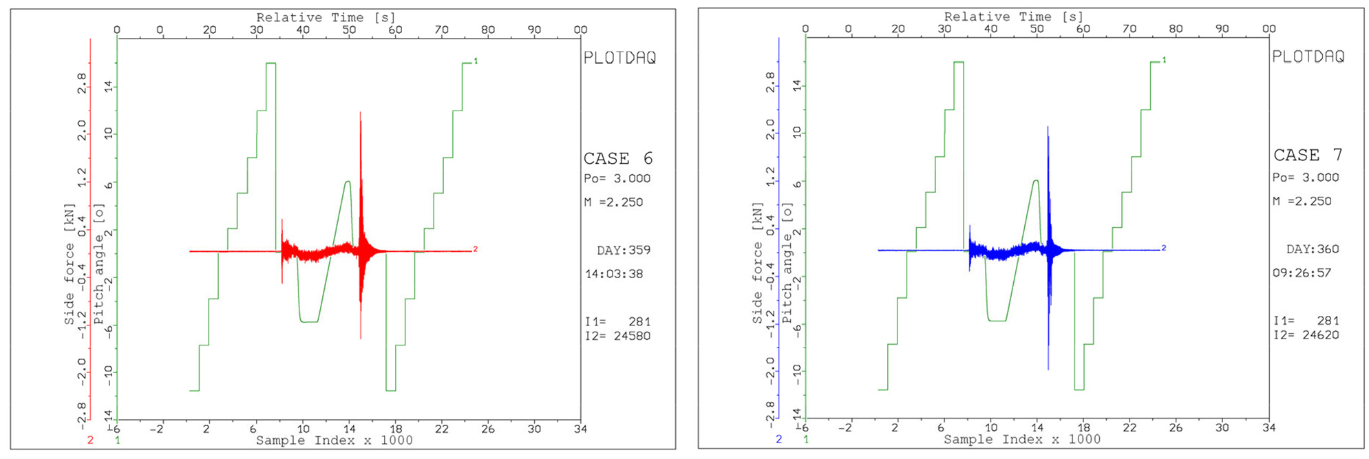
A relief of the internal wind tunnel balance by producing forced contacts during transient phases of the run was successfully confirmed in case 7. There were no model-sting contacts during the steady-flow part of the wind-on phase of wind tunnel runs and numerous contacts were recorded during the transient phases. Transient pitching and yawing moments were significantly reduced.
Locally produced PlotDAQ software was used for monitoring of raw sensors outputs that were used in the wind tunnel tests. Outputs from pitch encoder during model movement and from the sensor of the model/sting contact, recorded during data acquisition in the cases 6 and 7, are given in Figure 9. Plot labeled Pitch angle (line 1 in Figure 9) presents outputs from pitch encoder during model movement in engineering units. Plot labeled Contact (line 2 in Figure 9) presents outputs from the model/sting contact sensor in Volts.

Plot of channels outputs recorded during wind tunnel run sequences of the cases 6 and 7; Plot labeled Pitch angle (line 1) presents outputs from pitch encoder during model movement; Plot labeled Contact (line 2) presents outputs from the model/sting contact sensor; Pitch angle data are in engineering units; Contact data are in Volts.
During wind tunnel runs the level of the transient loads were monitored by the data acquisition system. Analog input signals from the wind tunnel balances are low-pass filtered in order to reduce electrical and mechanical noise and “smooth” the data. 15 This tends to filter-out the dynamic starting loads. So, whenever a high-Mach test is prepared for the VTI T-38 wind tunnel, the data acquisition system always have to be arranged in a way to monitor and parallelly record the unfiltered data with the filtered data from the wind tunnel balance components. The data acquisition system is always set to record the data taken during starting and stopping phases of the wind tunnel runs. During a wind tunnel run, the unfiltered recorded signals from the balance are checked against preset safety limits and the data acquisition software can automatically stop the run if transients exceeded permissible values.
After each wind tunnel run the magnitude and character of recorded starting loads are checked on the basis of the unfiltered balance data. Plots in Figures 10 to 13 present the balance component outputs recorded during wind tunnel run sequences of the cases 6 and 7. Pitch angle plot (line 1 in Figures 10 and 13) presents outputs from pitch encoder during model movement. Plot labeled Side force (line 2 in Figure 10) presents total side force Fy calculated on the basis of unfiltered outputs from N1 and N2 channels recorded in the balance measurement. Plot labeled Yawing moment (line 2 in Figure 11) presents total yawing moment Mz calculated on the basis of unfiltered outputs from N1 and N2 channels recorded in the balance measurement. Plot labeled Normal force (line 2 in Figure 12) presents total normal force Fz calculated on the basis of unfiltered outputs from S1 and S2 channels recorded in the balance measurement. Plot labeled Pitching moment (line 2 in Figure 13) presents total pitching moment My calculated on the basis of unfiltered outputs from S1 and S2 channels recorded in the balance measurement.
Plot of channels outputs recorded during wind tunnel run sequences of the cases 6 and 7; Plot labeled Pitch angle (line 1) presents outputs from pitch encoder during model movement; Plot labeled Side force (line 2) presents total side force Fy on the basis of unfiltered outputs recorded in the balance measurement; All data are given in engineering units.

Plot of channels outputs recorded during wind tunnel run sequences of the cases 6 and 7; Plot labeled Pitch angle (line 1) presents outputs from pitch encoder during model movement; Plot labeled Yawing moment (line 2) presents total yawing moment Mz on the basis of unfiltered outputs recorded in the balance measurement; All data are given in engineering units.

Plot of channels outputs recorded during wind tunnel run sequences of the cases 6 and 7; Plot labeled Pitch angle (line 1) presents outputs from pitch encoder during model movement; Plot labeled Normal force (line 2) presents total normal force Fz on the basis of unfiltered outputs recorded in the balance measurement; All data are given in engineering units.

Plot of channels outputs recorded during wind tunnel run sequences of the cases 6 and 7; Plot labeled Pitch angle (line 1) presents outputs from pitch encoder during model movement; Plot labeled Pitching moment (line 2) presents total pitching moment My on the basis of unfiltered outputs recorded in the balance measurement; All data are given in engineering units.
Table 4 shows maximum transient loads during start or stop of wind tunnel runs monitored and collected from plots in Figures 10 to 13. Loads were checked with respect to the nominal loads rhombus of the balance and given in Figures 14 and 15 for both balance planes. For clarity, maximum transient loads during start/stop of wind tunnel phases were shown only in the first quadrants of the graphs.
Maximum transient loads during start or stop of wind tunnel runs monitored in PlotDAQ.


Loads rhombus of the Able MkXV wind tunnel balance in the N1N2 plane for −90° rotated balance; Maximum transient loads during start/stop of wind-on phases were added only in the first quadrant.

Loads rhombus of the Able MkXV wind tunnel balance in the S1S2 plane for −90° rotated balance; Maximum transient loads during start/stop of wind-on phases were added only in the first quadrant.
Transient pitching and yawing moments on the balance were reduced by about 50% as expected, but transient force loads were not, which, too, was expected. 15 Both the decrease of moments and the increase of forces are understandable: the model on a force-type balance can be thought of as a beam on two slightly elastic supports (i.e. the fore and aft sensing elements in the balance) placed some distance apart. When a third support (the point of model-sting contact), acting as a lever fulcrum, is added at a relatively large distance from the two supports, the distance between the outermost supports is significantly increased and the force couple of support reactions (i.e. the physically measured load components) to the applied moments is reduced. However, with respect the force loads, the support reaction that is nearer to the added fulcrum than the center of pressure, may increase, and the total measured force may increase.
Although the moment loads acting on the balance were significantly reduced in the presented test, both the model and the sting were still exposed to high transient loads. However, as the transient moments threatening to endanger the balance were significantly reduced, the complete supersonic test program was realized with no fear of balance damage.
It should be noted that, while force measurements with internal wind tunnel balances are typically performed with low-pass filtering on the measurement channels from the components of the internal balances, unfiltered signals must be acquired in order to properly assess the dynamic nature of the starting loads. However, the use of unfiltered signals generally increases noise and reduces the accuracy of the force measurements. In the performed tests, this problem was solved by using two measurement channels for each balance component: one channel with low-pass filters for the computation of the forces and moments relevant for the purpose of the executed test, and another, unfiltered, channel, for the assessment of transient loads. Data were processed twice, using, alternatively, either the unfiltered channels (to determine the transient loads) or the filtered channels (to determine the aerodynamic coefficients required from the test). While the uncertainty of force measurements with internal wind tunnel balances is typically slightly better than 0.1%FS, the use of unfiltered channels degraded the uncertainty to about 0.5%FS.
Conclusions
By using several techniques, the initially existing problems related to high supersonic starting loads in the VTI T-38 wind tunnel were overcome to a large degree. Among the applied techniques is a simple method for the reduction of the supersonic starting loads on internal wind tunnel balances, based on forced model-sting contact, which requires very little additional effort in the preparation of or during the wind tunnel test, and can be used in most test setups. Experience showed that the applied technique, on the basis of the forced model-sting contact, can reduce the starting loads by more than 50%, which has been shown using, as an example, a recent test of a supersonic projectile.
The applied technique has limitations in that it relieves only the wind tunnel balance of excessive loads, but not the model and the sting. Also, the technique is not convenient for tests at high angles of attack because it cannot differentiate between dynamic transient loads and high steady-state loads at high incidence. However, though it is not a complete remedy for starting loads, the technique of forced model-sting contact can contribute significantly to the reduction of the critical starting moments loads on the internal balance in tests of typical slender models at angles of attack up to approximately 20°. The forced model-sting contact technique can be applied in all wind tunnel as a means of alleviating the problem of high transient loads, particularly in the facilities which do not have mechanical provisions for protection of models during the starting/stopping phenomena.
Footnotes
Appendix
Handling Editor: Chenhui Liang
Declaration of conflicting interests
The author(s) declared no potential conflicts of interest with respect to the research, authorship, and/or publication of this article.
Funding
The author(s) received no financial support for the research, authorship, and/or publication of this article.