
Abstract
To reveal the influence of pit units on the friction and wear performance of multi-rollers-sliding-rolling tribo-pairs (MRSRTs), the tribological behavior of pits textured MRSRTs with 18 rollers under periodic varied load and dry wear were researched. The texture parameters include: diameter of pits (DAOP, 200, 250, and 300 μm), depth of pits (DPOP, 10, 20, and 30 μm). The wear losses and worn surfaces of samples were obtained. The influence mechanism of pits on the tribological performance of MRSRT was also discussed. The results show that: The average coefficients of friction (COFs) of pits textured MRSRTs are all lower than that of smooth one under periodic varied load and dry wear. Their mass losses are almost all higher than that of smooth MRSRT. The influence of DPOP on the tribological properties of textured MRSRTs is significant and continuous compared with that of DAOP. The depth-diameter ratio is an important factor for the wear losses. In this work, when the DAOP is 200 μm and the DPOP is 30 μm, that is, the depth-diameter ratio is 0.15, compared with the smooth sample, the mass loss of MRSRT is reduced by about 13%, and its average COF is reduced by 30.5%. This work can provide a valuable reference for the surface design and optimization of rolling element bearings.
Introduction
In mechanical system, rolling element bearings (REBs) are mainly used to support parts, bear axial or radial loads and limit the movement of shaft along the axial direction. REBs may be cheap, but its failure will be costly. The friction and wear between washers and rollers, which belongs to multi-rollers sliding-rolling tribo-pairs (MRSRTs), is undesirable and inevitable. To prolong the serve life of REB, it is of great significance to improve the tribological behavior of the MRSRT itself, and postpone the transition points between mild wear and severe wear. 1
However, as for mechanical parts, for example, seals, gears, bearings (journal bearings, thrust bearings and REBs), only their surface properties (i.e. roughness, hardness and topography) can be customized partially, according to individual requirements. In this case, the surface modification technologies, including physical/chemical vapor deposition (P/CVD),2,3 laser remelting (LR), 4 surface texture/laser surface texture (ST/LST),5–12 laser cladding (LC), 13 are put forward. Among above mentioned methods, ST/LST has proved to be a cost-effective and fast way to tune the tribological performance of sliding/rolling/sliding-rolling tribo-pairs, by preparing periodically distributed macro-/micro units, for example, pillar, pit, groove and grid, on the target surfaces in a pattern.14–26 However, almost all publications focus on journal bearings, thrust bearings or sliding tribo-pairs, which should be attributed to their convenience in texture preparation. In the past 50 years, few work have been done around the friction and wear performance of textured MRSRTs 27 : Leiro et al. evaluated the dry rolling/sliding (rolling with 5% sliding) wear behavior of Si alloyed carbide free bainitic steel (60SiCr7 spring steel) austempered at different temperatures (250°C, 300°C, and 350°C) using self mated disks for three different test cycles, namely 6000, 18,000, and 30,000 cycles. 28 Liu et al. 29 investigated the dry rolling-sliding wear behaviors of three types of pearlitic steel and one carbide-free bainitic rail steel. Hu et al. 30 performed rolling-sliding wear experiments to investigate the wear and rolling contact fatigue (RCF) behaviors of a premium pearlitic rail, a carbon-free bainitic rail and two standard pearlitic rails (U71Mn and U75V). Boidi et al. 31 conducted a series of ball-on-disk tests to scrutinize the influence of three texture configurations fabricated by LST on the tribological performance of elastohydrodynamic (EHD) point contacts under different slide-to-roll ratios (SRR), entrainment velocities and inlet temperatures. Xu et al. 32 researched the effect of slippage rate on the tribological behavior of high-tungsten high-speed steel (HTHSS) under high-pressure contact by using a self-made ring-on-ring wear tester. However, all above publications mainly focused on the friction and wear properties of single-roller (two disks) tribo-pair under a fixed or variable sliding-rolling ratio, without surface texture. The influence mechanism of texture patterns on the wear behavior of MRSRTs is still unclear, especially under variable load and dry wear.
High temperature, high speed, light load (or zero load or even direction-variable axial load), and starved lubrication (even dry wear) are the worst working conditions of aviation bearings. When jet fighter is doing tumbling and other violent movements (like the Pugachev Cobra maneuver, Tail slide, and Herbst turn etc.), the aviation bearings may be in the state of no lubrication or even dry wear for a while (usually less than 30 s), which is harmful for all kinds of bearings. The tribological properties of textured MRSRTs under dry wear can best reflect the wear resistance and friction-reduction ability of the texture itself. So, based on previous works,33–38 considering its unique rolling-sliding feature and separating structure, the shaft washer and rollers (with a nylon cage) of 81107TN bearing were used as samples and counterparts respectively, to research the influence of pit’s dimensions on the tribological performance of MRSRTs under periodic varied load and dry wear. Their friction and wear performance as well as the influence mechanism of pits on the tribological behavior were compared and discussed. This work would provide a valuable reference for the raceway design and reliability optimization of rolling elements bearings.
Materials and modeling
The sketch and dimensions of used MRSRT are shown in Figure 1(a). If the linear velocity of the center of one roller is set as VR, the linear velocity of its inner end, VRa, will be lower than VR, and the linear velocity of its outer end, VRb, will be higher than VR, although they have the same angle velocity, ω. This means that there are obvious sliding phenomena existed at both ends of rollers. So, considering the consistency of material and heat treatment, the shaft washer of 81107TN bearing is chosen as the sample, while the rollers (with a nylon cage, PA66) of bearings are chosen as the counterparts. The shaft washer and rollers are all fabricated by GCr15, and their surface harnesses are about 60 ± 1 HRC.
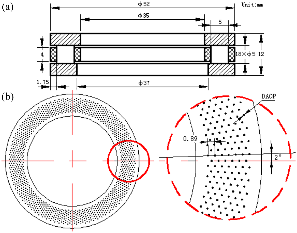
Sketch of pits textured MRSRT: (a) dimensions of 81107TN bearing and (b) definition of pattern parameters.
As shown in Figure 1, the pattern parameters include: diameter of pits (DAOP, 200, 250, and 300 μm), depth of pits (DPOP, 10, 20, and 30 μm), distance between two adjacent pits as well as the circumferential interval angle. Therefore, the range of depth-diameter ratio is from 0.033 to 1.5. Through previous repeated trials and tests, the distance between two adjacent pits and the circumferential interval angle are set as 0.89 mm and 2.0°, respectively (see Figure 1(b)). To reveal the influence of different DAOPs and DPOPs on the tribological properties of MRSRTs under periodic varied load and dry wear, there were nine groups used and marked as G01-G09 (see Table 1).
Pattern parameters of MRSRT groups.
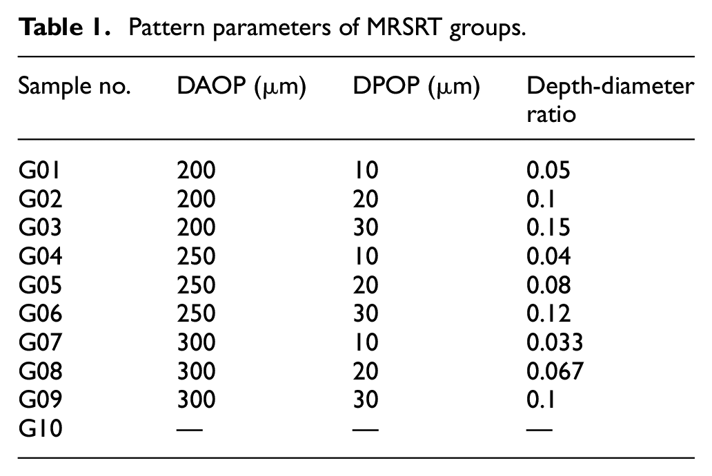
In order to reduce the influence of accidental and human factors on the test data, one group includes three samples and are tested three times. A group of smooth samples was introduced as a reference, and coded as G10. Thus, the total number of MRSRTs consumed is 10 × 3 = 30. Prior to wear tests, all groups were pre-treated as the following steps: First, remove the antirust grease of samples, wash and dry them; Second, process different pit patterns on the raceways of shaft washers of G01-G09 through a laser marking system (PL100-30W, China); Third, polish the textured shaft washers with SiC papers (from #400 to #2000 grades); Finally, clean the polished washers in a ultrasonic cleaner (VGT-1620QTD, China) for 15 min, and dry them by a hot-air blower. The parameters of laser marking system are listed as follows: laser wave length of 1064 μm; laser power of 30 W; scanning speed of 100 mm/s; frequency of 72 kHz. Note that: only the raceways of shaft washers of samples are textured.
The tribological properties of pits textured MRSRTs were tested using a MMW-1A wear test rig (Huaxing Jinan, China) with a customized chucking (see Figure 2(a)). Through repeated trials and tests, the parameters of tribometer were set as follows: vertical load, 2600–3000 N, with a manual switching every 1800 s (see Figure 2(b)); rotating speed, 250 rpm; test duration, 18,000 s. Wear tests were all carried out at room temperature. An electronic analytical balance (EX225D, Ohaus) with a precision of 0.1 mg (0.01 mg readability) was used to measure their wear losses. A 3D surface profilometer (VK-1050, Keyence, Japan) was used to characterize their worn surfaces. Note that: the COF curve of each group is the mean value curve of three tests. The mass loss of each group is the average of nine measurements of three MRSRTs. So, the difference of COFs and mass losses is credible and valuable, which can be used to analyze the tribological behavior of MRSRTs with different DAOPs and DPOPs.

Sketch of the customized MRSRT and the applied load curve: (a) sketch of MRSRT, (b) curve of periodic varied load, and (c) curve of fixed load.
Experimental results
Friction coefficients
To better compare the difference of COF curves of MRSRTs, the average COF line and COF curve of smooth group are both added as references. Figure 3 shows the COF curves of MRSRTs under periodic varied load and dry wear. The label “G01: 200-10” means “Group code: DAOP-DPOP.” As shown in the figures, the COF curves of pits textured MRSRTs are almost all lower than that of smooth one in this condition, except for G02.

COF curves of MRSRTs under periodic varied load and dry wear: (a) DAOP is 200 μm, (b) DPOP is 10 μm, (c) DAOP is 250 μm, (d) DPOP is 20 μm, (e) DAOP is 300 μm, and (f) DPOP is 30 μm.
Wear losses and worn surfaces
Figure 4 compares the mass losses of shaft washers and average COFs of MRSRTs under periodic varied load and dry wear. As shown in the figure, among all groups, the average COF of G02 is the highest and the average COFs of G03, G04, and G07 are much lower than those of other MRSRTs. The mass losses of almost all pits textured groups are higher than that of smooth one (2.99 mg), except for G02 and G03. Specifically, the wear loss of G02 is the lowest and only 2.22 mg. The loss of G06 (3.11 mg) is a little higher than that of G10. The losses of G01, G04, and G07 are obviously higher than those of groups with the same DAOP. The significant error bars in the figure should been attributed to the dramatically variations of their COF curves.

Mass losses of the shaft washers and average COFs of MRSRTs.
Worn surfaces
Figure 5 shows the unwashed worn surfaces of the shaft washers of MRSRTs under periodic varied load and dry wear. As shown in the figure, there are nylon films left on the outsides of worn surfaces of all groups, especially the smooth one. There is a lot of nylon powder stored in the outside pits (see the red circles) too, especially when the DPOP is deep, 20 or 30 μm.
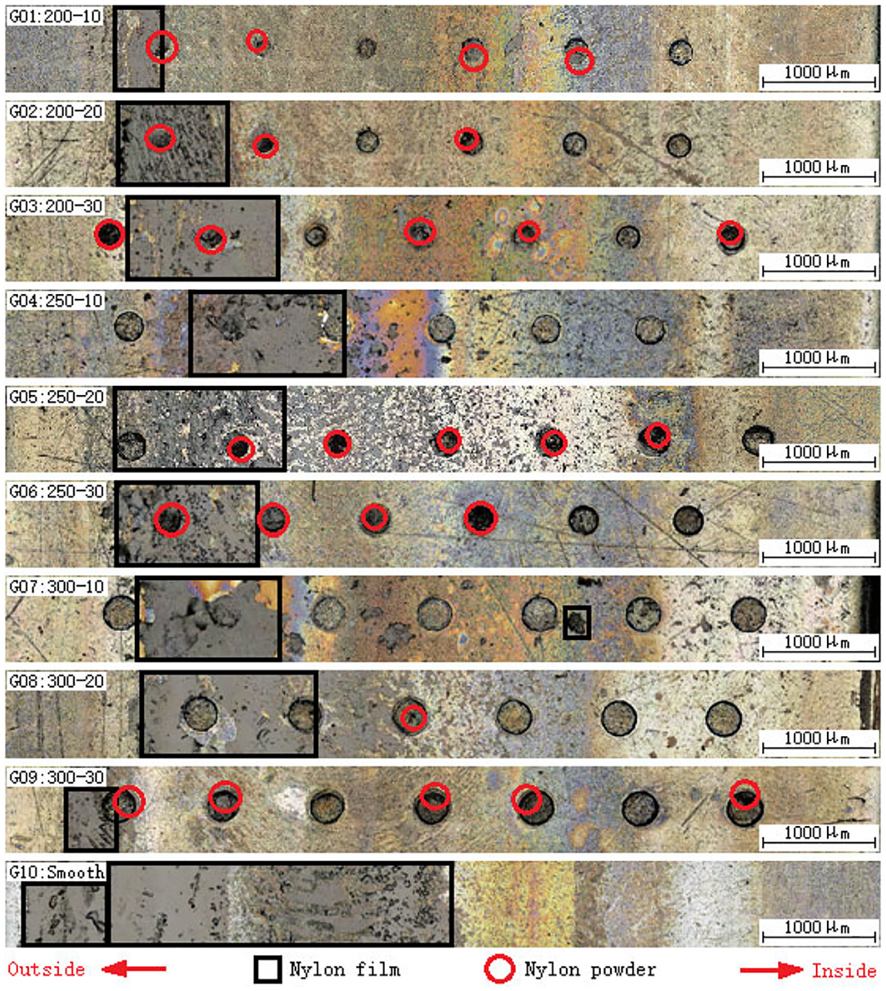
Unwashed worn surfaces of the shaft washers of MRSRTs.
The roughness of nylon film and other regions are shown in Figure 6(a). The Fourier transform infrared spectroscopy (FTIR, IS10, Thermo Fisher Scientific, USA) was used to identify the material types of the film and the obvious infrared characteristic spectrum of nylon was found (see Figure 6(b)). Figure 7 shows the ultrasonic washed worn surfaces of the shaft washers of MRSRTs. Apparently, there are high-temperature regions on the surfaces of all groups and the burning marks of G03, G04, G07, and G10 are quite serious than those of others. In the meantime, there are significant “edge collapse” phenomena around pit units for textured groups, especially G03, G04, and G07. Based on the worn surfaces, the wear pattern of all samples under periodic varied load and dry wear is mainly abrasive wear combined with fatigue pitting. Furthermore, there is serious “arch-shape stripes” on the worn surface of smooth sample (G10), caused by the serious sliding wear.
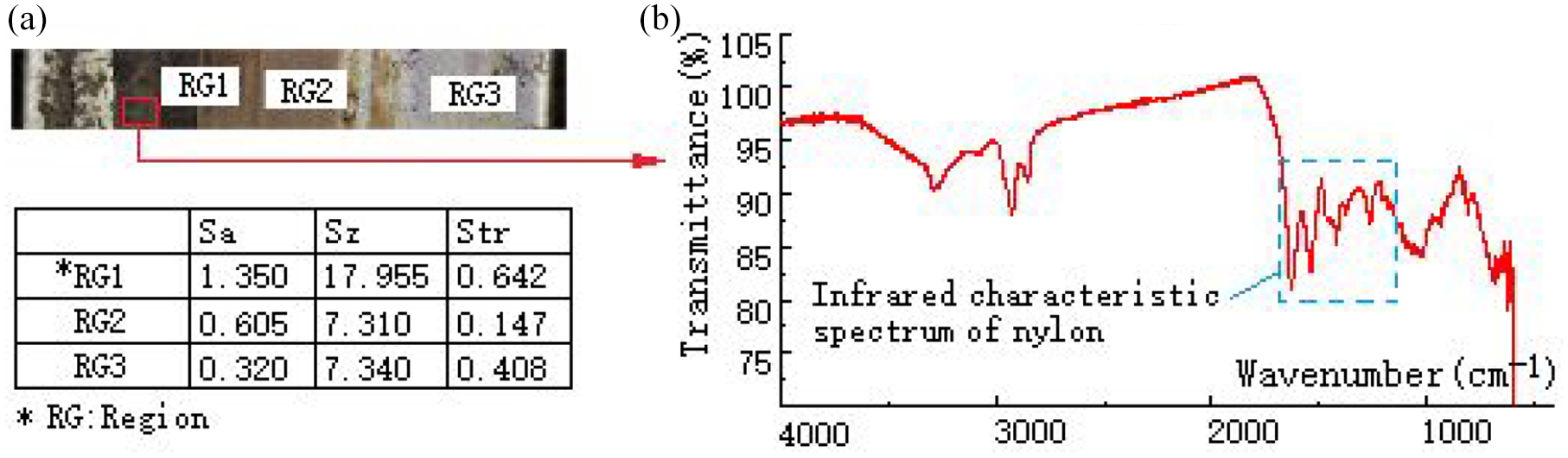
Roughness of different regions of worn surface (G10, under fixed load) and the FTIR curve: (a) roughness of different regions and (b) characteristic spectrum of nylon measured through FTIR.

Ultrasonic washed worn surfaces of the shaft washers of MRSRTs.
Discussion
Effect of DAOP on the tribological behavior
When the DAOP is fixed, whether 200, 250, or 300 μm, the average COFs of MRSRTs increase first and then get smaller with the increase of DPOP (see Figure 4). This is because when the DAOP keeps unchanged, the high DPOP means large effective volume of pits and the restricted movement of nylon powder along radial direction under centrifugal force. 39 The high COF between nylon and steel is the reason for the first increase of average COFs. When the DPOP is deep enough, the nylon films get reduced (see G06 and G09 in Figure 5), the average COF also decreases instead. Specifically, when the DAOP is 200 μm, as shown in Figure 3(a), the curve of G02 is relatively high and three curves can be easily distinguished, indicating the influence of DAOP on the COFs is significant. As the DAOP is 250 μm, three curves in Figure 3(c) are all lower than that of smooth group and can be distinguished easily too. While the DAOP is 300 μm, three curves are mixed together and become hard to read (see Figure 3(e)), implying the reduced effect of DAOP on the COFs in this condition.
Meanwhile, when the DAOP is 200 and 300 μm, the mass losses of MRSRTs (G01–G03, G07–G09) decrease first and then get higher with the change of DPOP, from 10 to 30 μm (see Figure 4). While the DAOP is 250 μm, the losses of G04-G06 decrease with the increase of DPOP. This is because as the DPOP is too high, which may induce serious edge collapse around pit units (see Figure 5), increase the metal debris left in MRSRTs and deteriorate the wear of them. In addition, the difference of three losses of G07–G09 is quite small, indicating the weak influence of the DAOP on the wear losses in this case too.
Effect of DPOP on the tribological behavior
As shown in Figure 3, when the DPOP increases from 10 to 30 μm and keeps fixed, all COF curves can be distinguished, indicating the significant influence of the DPOP on the tribological performance of MRSRTs. Specifically, as the DPOP is 10 μm, three curves are close (see Figure 3(b)) and the average COFs of G01, G04, and G07 decease with the increase of DAOP. When the DPOP is 20 μm, the distance of three curves becomes longer (see Figure 3(d)). The average COFs of G02, G05, and G08 decrease with the change of DAOP (from 200 to 300 μm). While the DPOP is 30 μm, the curves of G03, G06, and G09 get closer again (see Figure 3(f)) but their average COFs increase with the change of DAOP first and then decrease. This is because when the DPOP is fixed, the increase of DAOP means the decrease of effective contact area, the increase of contact stress, 38 the increase of effective volume of pit units, serious collapse of pit’s edge and intense centrifugal movement of nylon powder along radial direction. But the above factors are mutually restricted and mutually affected, and the final wear performance of pits textured bearings depends on their balance. The depth-diameter ratios of MRSRTs can reflect this balance in some degree.
Equally, as the DPOP is 10 μm, the mass losses of G01, G04, and G07 increase first and then get down with the variation of DAOP, from 200 to 300 μm. Their values are almost the highest among those of groups with the same DAOP. When the DPOP is 20 μm, the mass losses of G02, G05, and G08 increase first and then drop down with the change of DAOP too. While the DPOP is 30 μm, the losses of G03, G06, and G09 increase gradually with the variation of DAOP, indicating the influence of the DAOP on the wear losses of MRSRTs is significant and continuous. The excellent wear resistance of G02, G03, and G06 should be attributed to their suitable depth-diameter ratios, which are 0.10, 0.15, and 0.12, respectively. The big DPOP is the reason for the high loss of G09.
Difference between periodic varied load and fixed load
To reveal the difference of the tribological behavior of MRSRTs between periodic varied load (2600–3000 N) and fixed load (2600 N, see Figure 2(c)), the wear tests under fixed load and dry wear were conducted too, using three smooth MRSRTs.
As shown in Figure 8, the COF curve under fixed load is basically consistent with the curve under periodic varied load, but its fluctuation is more stable in the later period. Its average COF is about 95% of that of under periodic varied load. As for wear volume, the mass loss under fixed load is 5.74 mg, which is about 192% of the loss under periodic varied load. This should be attributed to the well mechanical properties of nylon and the large nylon film left under periodic varied load (see Figure 9). In addition, there are “arch-shape stripes” existed on the raceway surface of MRSRT under fixed load too, but it is far less serious than that under periodic varied load. This should be attributed to the stacking effect of nylon powder under periodic varied load, which cause the serious sliding phenomena of MRSRTs.
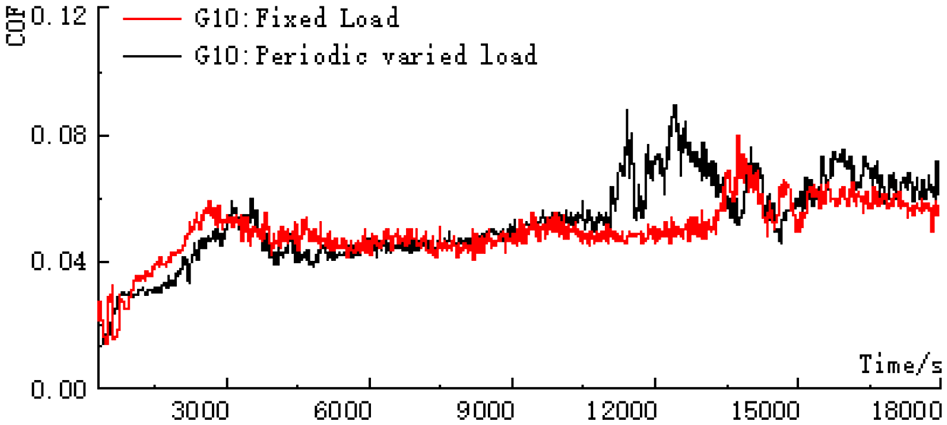
COF curves of smooth MRSRTs under periodic varied load and fixed load.

Worn surfaces of the shaft washers of smooth MRSRTs under periodic varied load and fixed load.
Influence mechanism of pits on the tribological properties
When MRSRTs are tested under dry wear, due to the direct contact between rollers and pockets, there is a large amount of nylon powder generated during testing. Nylon powder left on the raceway will increase the rolling resistance of the system and even causes the jam of rollers, which further fast the rising of system temperature. 40 With the rapid increase of system temperature, the nylon powder melts quickly and nylon film forms. Meanwhile, owing to the obvious circumferential linear velocity difference of two ends of rollers, the thickness of nylon films along the radius direction is not uniform.34–36,38 Finally, the frictional-induced heat, nylon powder as well as the system temperature gets to a dynamic balance, and the nylon films are mainly left on the outsides of raceways (see Figure 5). For the COF between nylon and is much higher than that between steel and steel, the large area uneven nylon film and the high roughness of nylon film regions (see Figures 6(a) and 9) are the main reasons for the high average COFs of smooth MRSRTs under periodic varied load and dry wear. The self-lubricating feature and well wear-resistance of nylon is the reason for the low mass losses of smooth group.
The influence of pit units on the friction and wear properties of MRSRTs under periodic varied load and dry wear can be summarized and listed as follows: (1) The pits can effectively collect and hold metal debris and nylon powder. Under the action of the centrifugal force during high-speed rotation, the nylon powder moves from the inside to the outside along the radius direction and the amount of debris left on the textured raceway is significantly reduced compared with smooth sample. (2) Pit units destroy the integrity of textured raceways and change the surface stress distributions of textured MRSRTs significantly.34–36,38 Furthermore, the surface material of textured MRSRT can be regarded as numerous “micro-cantilever-beams.”34,35 According to the theory of theoretical mechanics, the increase of the length of “micro-cantilever-beams” will significantly reduce the shear resistance of the surface material of MRSRT, especially the material around pits. (3) Due to the “local quenching effect” during laser marking process, there is a phase transformation layer around the pit unit,34,38 which is helpful to improve the contact fatigue and thermal fatigue performance of MRSRTs, and further improve their fatigue wear resistances. 4 (4) Limited by the function and performance of the wear test rig, the axial external load cannot change automatically and rapidly. Thus, the tribological behavior of the MRSRTs under the periodical fast-varying load has not been revealed and needs to be studied in the future. In this work, compared with the data under fixed load, the slowly periodically varying load leads to the increase of contact stress in the contact area at the moment of load-change (especially at the edge of the pits) and breaks the migration of wear debris and nylon powder along the radial direction, resulting in the high amount of wear debris and nylon powder remaining on the surface of the MRSRTs. Correspondingly, the area of nylon film in this condition is larger and more uneven, which finally increases their average COFs.
Conclusions
To reveal the influence of pit units on the tribological behavior of the MRSRTs under periodic varied load and dry wear, a laser marking system and a MMX-1A wear test rig were used to research the friction and wear properties of MRSRTs with different DAOPs and DPOPs. Based on the experimental and characterization data, the following conclusions could be drawn:
When MRSRTs are tested under periodic varied load and dry wear, the average COFs of pits textured groups are all lower than that of smooth one. Their mass losses are almost all higher than that of smooth group, except for G02 and G03. There is un-even nylon film left on the worn surfaces of all groups, whether textured or smooth, which directly affects the final tribological behavior of MRSRTs for its high surface roughness, self-lubricating feature and well wear-resistance.
The influence of DAOP on the friction coefficients and mass losses of textured MRSRTs gets reduced with its increase, from 200 to 300 μm. The influence of DPOP on the tribological performance of textured groups is significant and continuous, whether it is 10, 20, or 30 μm. The depth-diameter ratio can reflect the comprehensive tribological performance of pits textured MRSRTs.
The COF of MRSRT under periodic varied load is slightly larger than that under fixed load, while its wear loss is much smaller than that under fixed force. The final tribological properties of pits textured MRSRTs under periodic varied load and dry wear are determined by the following factors: the effective contact area, surface contact stress, nylon film, fatigue peeled of material along the edges of pits, loads, etc. In this work, when the DAOP is 200 μm and the DPOP is 30 μm, that is, G03 (with a depth-diameter of 0.15), compared with the smooth group, its mass loss is reduced by about 13% and its average COF is reduced by 30.5%, showing wonderful wear resistance and friction-reducing effect under periodic varied load and dry wear.
Footnotes
Handling Editor: Chenhui Liang
Declaration of conflicting interests
The author(s) declared no potential conflicts of interest with respect to the research, authorship, and/or publication of this article.
Funding
The author(s) disclosed receipt of the following financial support for the research, authorship, and/or publication of this article: The research was supported by the National Natural Science Foundation of China (No. U1708254), the National Key R & D Program of China (No. 2019YFB2004400), the National Natural Science Foundation of China Young Scientist Fund (No. 51901141), the Natural Science Foundation of Liaoning province (No. 2019-MS-258) and the Scientific Research Fund of Liaoning Provincial Education Department (No. LJ2019003).