
Abstract
This paper proposes a microstructure, the flexible unit, employing the leaf spring working principle in machinery. The flexible unit has elasticity and damping capability. Parts using flexible units produce greater elastic deformation than rigid parts under great impact external loads, thus absorbing and consuming large energy amounts during deformation. First, the flexible unit’s structural form and layout designs are presented. Second, the constraint conditions for the flexible unit’s structural parameters are given according to selective laser melting process characteristics. Third, flexible units with different parameters are selected and produced using selective laser melting. The influences of the flexible unit’s structural parameters on the mechanical properties and energy absorption are then analyzed from compression test results. Finally, the strength and energy absorption of the common Kagome structure and the flexible unit are compared. The results show that the flexible unit’s yield strength is ~36% higher than a Kagome structure with the same mass. The flexible unit’s absorbed energy is ~27% higher when damaged and ~39% higher during elastic deformation than for the Kagome structure. Thus, flexible units have demonstrably excellent performance, so their design and application provide an alternative for the lightweight and miniaturized design of parts with large impact loads.
Keywords
Introduction
Impact is one of the most important loads for mechanical parts in aerospace and aviation equipment, so these parts have higher requirements for impact resistance. Because the material impact strength is determined, improving the impact resistance means increasing the mass and volume of the mechanical part if traditional processing techniques are used. Because of this, weight and performance have always been a prominent contradiction in the design and manufacture of equipment, especially aerospace equipment.
Researchers have investigated strengthening the impact resistance of components in various ways, including material composition, composite materials, and material structure improvement. With the rapid development of additive manufacturing technology, some researchers have used this technology to print structures with high impact resistance directly into the mechanical parts in the form of cells so that the parts have the corresponding impact resistance. Present commonly-used additive manufacturing cell structures with impact resistance mainly include honeycomb, foam, and lattice structures.
A honeycomb structure is a complex structure consisting of honeycomb holes alternating with a skeleton. The structure has high strength, is lightweight, has good sound and heat insulation, and has good vibration energy absorption performance. He et al. 1 designed the variable-density honeycomb support structure shown in Figure 1. The influence of the honeycomb structure with different design parameters on the compression resistance was analyzed using experiments. The residual stress on the surface of the honeycomb structure formed using selective laser melting (SLM) technology was measured, and the effect of different design parameters on the surface residual stress was studied.
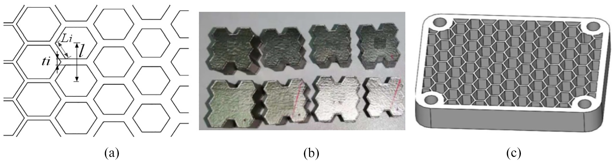
Variable-density honeycomb structure: (a) cells with varying wall thickness and side length; (b) cells made using the selective laser melting (SLM) method; (c) the part’s internal structure with a variable-density honeycomb structure.
Galeta et al. 2 measured and analyzed four structures: solid, honeycomb, round hole, and strip. The results showed that the honeycomb structure has the highest strength and can effectively reduce the mass of 3D printing parts, significantly reducing printing time and cost. Riss et al. 3 proposed a method to optimize the honeycomb structure according to the load and external boundary conditions. By changing the wall thickness, honeycomb diameter, and the number of honeycombs to achieve a lightweight structural design, the weight of the components designed by this method was reduced by about 50% compared with the traditional method. Li et al. 4 studied the impact characteristics of a honeycomb-like structure and found that its impact resistance was excellent.
Honeycomb structures have excellent performance but are difficult to manufacture using additive manufacturing because of their closed porous structure. Generally, additive manufacturing is used to process the inner core of a honeycomb structure, which is then connected to the part splint by welding or with an adhesive. In addition, because the metal honeycomb structure’s elastic deformation ability is poor, excellent shock resistance can be achieved only when plastic deformation is produced, making it challenging to apply to the parts that need to be repeatedly subjected to large impact loads.
Foam structures have excellent mechanical properties, including high specific strength, good insulating properties, strong impact resistance, and diverse designs, and are widely used in aerospace, automotive, marine, and other industries. Pinto et al. 5 compared the performance differences between single-sized and dual-sized foamed aluminum structures. The non-metallic prototypes of these two aluminum foam structures were printed using additive manufacturing technology, and the final metal structure was machined by casting, as shown in Figure 2(a). Through compression tests on the two structures, it was found that the stiffness of the double-sized foamed aluminum structure increased by 29%, the compressive strength increased by 83%, and the energy absorption capacity improved by more than 27% compared with the single-sized foamed aluminum structure. The foam structure has excellent impact resistance.

Foam structure: (a) uniform size and dual size; (b) for human tissue regeneration scaffolds.
To reduce the weight of motorcycle helmets, Pinnoji et al. 6 used finite element analysis and conducted experiments to compare and analyze the impact resistance of low-density metal foam structures and ABS (acrylonitrile butadiene styrene) helmets. The experimental results showed that the low-density metal foam has large plastic deformation locally in the impact area, and the impact force and peak acceleration value of the head are both lower than for ABS. Compared with an ABS helmet with the same density, the low-density metal foam structure helmet reduces the normal stress at the front and top by about 25% and 22%, respectively.
Kumar et al. 7 studied the effect of different foam structure types, hole units, and porosity on stents’ performance for human tissue regeneration, shown in Figure 2(b). The tests conducted verified the stents’ mechanical properties. By adopting a gradient porosity method, greater weight reduction of the stent structure can be obtained while ensuring higher impact absorption capability and tensile compression performance.
It should be noted that the foam structure is a non-periodic structure and uneven material distribution is common, resulting in unstable local strength and modulus and making it unsuitable for high strength and stability applications. Furthermore, additive methods have poor manufacturability for foam structures. Generally, it is necessary to print the non-metal mold of the part first and then use investment casting to process the parts. The foam structure also absorbs the energy from the impact load through plastic deformation and destruction. Therefore, it is difficult to meet the requirements for parts that must repeatedly withstand large impact loads.
There are many types of lattice structures. Ullah et al. 8 compared four typical lattice structures, including cylindrical lattice, body-centered cubic lattice, face-centered cubic lattice, and Kagome lattice structures, as shown in Figure 3. Through compression tests, shear tests, and other comparisons of its compressive performance and energy absorption capacity, it was shown that the Kagome structure has superior strength compared with other conventional lattice structures, and its energy absorption capacity is comparable to that of aluminum and titanium alloy honeycomb structures. Moon et al. 9 compared the performance of the three-dimensional Kagome structure, three-dimensional pyramid structure, and hexagonal diamond structure under requirements of strong adaptability, low energy consumption, low weight, and high flexibility for a drone wing. The three-dimensional Kagome structure had the highest bearing capacity, while the hexagonal diamond structure had the best energy absorption capability. The UAV wing was then redesigned and processed using the Kagome structure.

Four typical lattice structures: (a) Kagome structures; (b) body-centered cubic (bcc); (c) face-centered cubic (f2cc); (d) combination of bcc and f2bcc (f2bcc).
This earlier research shows that some lattice structures, such as the Kagome structure, have excellent strength and energy absorption ability. However, the lattice structure is a rigid structure with small elastic deformation. It also consumes impact energy through its plastic deformation and structural damage. As a result, it is often used for disposable protective parts.
This paper describes a type of flexible unit based on the SLM technology that can absorb large amounts of energy during elastic deformation for parts that often withstand large shock loads. The structure and layout of the flexible unit were designed through theoretical analysis, and the SLM process characteristics and manufacturability constraints were studied. Then, three groups of flexible units with different structural parameters were manufactured using the SLM method, and compression tests were conducted. Based on this, the influence of unit structure parameters on its bearing capacity and energy absorption capacity was analyzed and compared with Kagome structures, demonstrating the advantages of the proposed design.
Design and performance analysis of flexible unit
Structural design of the flexible unit
The flexible unit needs a certain elastic deformation to absorb the energy generated during an impact. A leaf spring is a simple traditional mechanical structure with high strength, good cushioning and damping performance, and high reliability. The leaf spring structure is optimized based on SLM process requirements to design a flexible damping unit. This process is shown in Figure 4.

Structural design of the flexible unit.
The thickness of the leaf spring is increased, and the spacing between both ends is reduced to design a leaf spring structural unit suitable for SLM processing manufacturability requirements. Two leaf spring structures are assembled in series to form an elastic shell of the flexible unit to increase its deformation during loading and enhance its energy absorption capacity. The elastic shell parameters include the horizontal axis of the hole in the elastic shell 2a, the vertical axis 2b, the shell thickness m, the unit width n, and the unit height H. The elastic shell is symmetrical along the horizontal and vertical axes.
It should be noted that the flexible unit must have the same height H as in the application, and the performance analysis of the unit is generally established at a specific unit height. Changes in m, a, and b affect H. Because of the small supporting area size of the elastic shell upper end, the board hanging surface area is too large and difficult to process and does not meet the additive manufacturing process requirements. The flexible unit height studied in this paper is limited to H = 10 mm, which is also a typical height of the additive manufacturing unit structure. To ensure that the specified H is achieved, the vertical axis of the elastic shell is also limited to 2b = 8 mm. With the unit’s horizontal axis as the center, the portion other than H/2 of the unit is cut off to form the cut elastic shell.
According to the principle of energy dissipation in traditional mechanical structures, friction between structures is an important means of energy dissipation. In this paper, a friction hammer structure is designed inside the elastic shell based on the characteristics of the SLM process. The upper surface of the friction hammer is 0.3 mm from the elastic shell. When the elastic shell is elastically displaced after being impacted, the elastic shell and the friction hammer rub against each other to achieve friction between the flexible unit structures during the working process, increasing the unit’s capability to dissipate the impact energy.
Layout design of the flexible unit
The flexible unit is arranged as a function-supporting structure to the interior of the part so that the part itself can have the unit’s functionality. Possible flexible unit layout methods include wired, rectangular, circular, and radioactive layouts. The rectangular layout method is used in this paper to ensure isotropic forces on the parts. Four flexible units constitute a group forming a small structure in the flexible unit application. Every two adjacent units in each structure are perpendicular, and the distance between unit centers is L, as shown in Figure 5. Then, according to the structure and force characteristics of the applied parts, the small structures are arrayed to ensure additive process manufacturability. The edges of less than one unit provide support to the lattice structure.

Layout design of the flexible unit.
Generally,
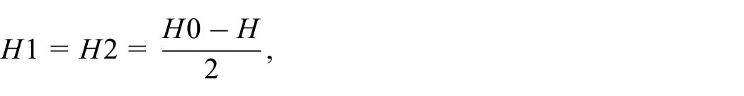
where H1 and H2 are, respectively, the upper and lower plate thicknesses of the part, H0 is the thickness of the part, and H is the unit thickness (see Figure 5).
The size of L directly affects the performance of the part. The smaller the L, the greater the strength of the part. At the same time, the quality of the part is also affected. If L is too small, the horizontal deformation space of the unit is insufficient, which affects the part’s performance. If L is too large, the suspended area of the part increases, which affects its manufacturability.
Manufacturability analysis of the flexible unit
At present, certain technological limitations exist in SLM technology and related equipment, so the design of the flexible unit must consider manufacturability. The main process constraints of the SLM technology consist of the minimum processing size constraint, the maximum inter-structure suspension size constraint, the minimum inclination angle constraint, and the maximum cantilever size constraint. When analyzing the process performance of currently used commercial SLM equipment, the constraints are as follows:
The size of the smallest columnar part that can be manufactured is 0.4 mm × 0.4 mm. When the part is smaller than this size, although it can be formed, the shape of the part is distorted.
The maximum allowable suspension support spacing between the part’s structure is 5 mm. But when the support interval is greater than 3 mm, the suspended regions of the parts has different degrees of collapse and deformation, thereby affecting their performance.
The minimum workable inclination angle of the part structure is 45°, and when the inclination angle is less than 45°, the structure is prone to warping deformation.
The maximum cantilever size of the part is 1 mm. When the cantilever size exceeds 1 mm, the cantilever boundary collapses or warps.
From the parameterization and layout analysis of the flexible unit, after defining the vertical axis b of the unit’s internal hole, the main structural parameters of the flexible unit include the horizontal axis a, the wall thickness m, the width n, and the layout parameter L. According to SLM process requirements, the design process of the flexible unit is as follows:
1. The wall thickness m and width n need to meet the SLM technology minimum manufacturable size requirement, i.e. m≥ 0.4 mm, and n≥ 0.4 mm. However, when m < 1 mm, the cell height requirement H = 10 mm cannot be satisfied, as shown in Figure 6(a). Therefore, the wall thickness m of the flexible unit is taken as:
m≥ 1 mm.
2. The curvature of the unit housing needs to meet the minimum inclination angle, and the curvature of the lower end of the unit housing should be greater than 45°. The point on the lowermost end of the cell casing is approximately on an ellipse whose horizontal axis is a1 = a+m and vertical axis b1 = b+m, as shown in Figure 6(b). The curvature of this point is obtained from the standard elliptical formula, so it is:

3. The unit’s layout needs to meet the maximum hanging size requirement of the SLM technology. The unit’s support area is increased, and the stress concentration when the unit is under load is eliminated by adding a chamfer with r = 1 mm to the junction between the unit and the part based on the maximum cantilever size constraint of the SLM process, as shown in Figure 6(c) where:

4. Figure 6(d) is a cross-sectional view of two units perpendicular to each other on the plane where the horizontal axis a lies. According to the layout design of the flexible unit, it is seen (where d is the horizontal deformation spacing reserved between units, take d≥ 0.5 mm):


Manufacturability constraints of the flexible unit: (a) value range of wall thickness m; (b) minimum inclination angle; (c) chamfer of junction between the unit and the part; (d) horizontal deformation spacing reserved between units.
A decrease in L increases the equivalent stress and the equivalent yield stress of the unit. However, L does not affect the performance of the unit alone but does affect the mechanical properties of the element after it is applied to the part with the layout parameter L. Therefore, the relationship between the unit’s structural parameters and mechanical properties does not need to consider the influence of L. However, L does affect the range of values of the unit’s structural parameters. At this time, for the convenience of the study, a fixed value can be assigned to L to study the manufacturability of the unit structure parameters in the case where L is equal to a specific value. In this paper, L = 9 mm is used.
In summary, to meet the SLM process constraints, the structural parameter constraints of the flexible unit are:

Equations (1) clarify the manufacturability domain of the flexible unit. When the flexible unit is designed, its structural parameters must meet the conditional constraints in the formulas.
The manufacturability range of the structural parameters of the flexible unit when L = 9 mm can be obtained from Equations (1). Using MATLAB to calculate the values, the structural parameter combinations that meet the manufacturability are determined. Table 1 shows some flexible unit parameter combinations and their SLM technology manufacturability.
Parameter combinations and manufacturability of some flexible units (all dimensions in mm).

Note: × indicates that it does not meet the selective laser melting (SLM) manufacturability requirements.
Preparation and performance tests of the flexible units
Three groups of unit structural parameter combinations were selected according to Equations (1) for manufacturing and compression tests to investigate their effect on the flexible unit’s mass, mechanical properties, and energy absorption capacity. With a = 2.6 mm and n = 4.6 mm, m is set as 2.5 mm, 2.7 mm, 2.9 mm, 3.1 mm, 3.3 mm. With m = 3.1 mm and n = 4.6 mm, a is set 2.2 mm, 2.4 mm, 2.6 mm, 2.8 mm, 3.0 mm. With m = 3.1 mm and a = 2.6 mm, n is 4.3 mm, 4.6 mm, 4.9 mm, 5.2 mm, 5.5 mm.
To better assess the mechanical properties of the flexible unit, the Kagome lattice structure was tested to compare the mechanical properties and energy absorption capacity. When the Kagome structure and the flexible unit have the same height h, the Kagome structure has the best mechanical properties for support diameter d = 1.2 mm, and inclination angle θ = 60°. 8
The samples were first designed in the Solidworks computer-aided design (CAD) software, then exported to STL format for slicing, and finally imported into the FS271M metal printer for manufacturing. All samples were annealed at 850°C and furnace-cooled to improve their overall mechanical properties.
Sample preparation and observation
This paper uses Ti6-Al-4V titanium alloy powder as the raw material. Its chemical composition is Al (5.5%–6.75%), V (3.5%–4.5%), impurity elements Fe (0.3% maximum), N (0.05% maximum), O (0.2% maximum), C (0.08% maximum), and H (0.015% maximum), and the balance Ti. The particle size is 15 μm to 45 μm, and the bulk density is 2.587 g/cm3 to 2.656 g/cm3. Parts made of Ti6-Al4-V titanium alloy have good mechanical properties, with tensile strength greater than 1100 MPa and yield strength of 1000±100 MPa. After the annealing process, the elongation after breaking can reach 13% or more.
In this paper, the test specimens were processed by an FS271M 3D metal printer developed by Farsoon Hi-Tech Co., Ltd, shown in Figure7(a). The maximum molding size is 275 mm × 275 mm × 320 mm, laser power is 225 W, powder coating thickness is 30 μm, scanning speed is 1000 mm/s, and spot size is 136 μm. The molding chamber is filled with argon as a protective gas throughout the printing process. The oxygen content is controlled below 1000 ppm to prevent the oxidation of parts during processing.

Selective laser melting (SLM) machine and specimens: (a) FS271M machine; (b) test specimens made by the machine.
There are two processed specimen types, as shown in Figure 7(b): the flexible unit and the Kagome lattice structure. Because of the molding space limitations of the FS271M machine, the specimens used in this paper were processed separately but strict consistency during both procedures. The time interval between the two processes is very short, so the influence of materials, machine equipment, and environmental factors on the performance of the test piece is avoided.
The theoretical mass is calculated, and the actual mass is measured for all specimens, as shown in Table 2. The actual mass of each sample produced by the SLM method is always higher than the theoretical mass. The flexible unit with a = 2.6 mm, m = 2.7 mm, and n = 4.6 mm has the largest mass difference of 6.57%. The reason for these differences is that the unit’s volume is small and its surface is large, so powder adhering to the surface greatly affects the unit’s mass. Because this powder is loose and does not provide any strength for the unit, appropriate methods should be considered to remove it.
Theoretical and actual masses of the specimens.

Compression tests of the flexible units
The equipment used for the compression tests is the WDW-100 universal material testing machine shown in Figure 8(a). It has a ±100 kN maximum load range, ±0.5% load measurement accuracy, and 5 mm/min loading speed. The entire test was conducted at room temperature. The stress–strain data for the test piece are collected by sensors.

Compression testing: (a) machine; (b) compression test procedure; (c) crushed units.
Figure 8(b) shows the compression process of a flexible unit with a=2.4 mm, m=2.7 mm, and n=4.6 mm. Figure 8(c) shows the crushed units.
Results and discussion
All specimens were machined successfully and were inspected using an electron microscope. No significant processing defects such as blowholes or warpage were found. However, the surface quality of the specimens was not high. When the part’s surface quality must meet a higher requirement, performing an appropriate post-surface treatment is necessary. After the specimen is processed, some loose powder may adhere to the sample’s surface, causing its mass to increase.
Broken locations of the flexible unit
Figure 9 shows several major failure modes of the flexible unit specimens after the compression test. It can be seen that although the destruction modes of the unit specimens are various, the fractured areas of the specimens are all on the edge of the unit end surfaces. The fracture surface is approximately perpendicular to the tangent plane of the unit shell. According to a preliminary analysis, the annular parts on both sides of the unit are free deformed parts, which are greatly deformed when loaded. The two ends of the unit are in direct contact with the test bench, which is not easily deformed, causing a dead space for the unit deformation. When the free deformed part of the unit reaches a certain degree of deformation, the stress at the joint between the two parts increases sharply and is damaged first.

Compression failure process of the flexible unit.
A camera was used to record the entire unit compression test process and analyze the yield failure to confirm the above analysis, as shown in Figure 9. In these pictures, the surface of the deformed unit becomes brighter and white, caused by the adhered surface powder surface falling off.
It can be seen that the unit does not deform easily from the beginning of the test to 9 s. When the test progresses to 32 s, the deformation at the horizontal axis of the unit shell is obvious, so it can be shown that the maximum stress is first generated at the horizontal axis of the unit shell. According to the unit’s characteristics at 57 s and 1 minute 28 s, the unit’s deformation starts from the shell’s horizontal axis and slowly expands to both ends. As the compression test continues, at 2 minutes and 9 s, the unit’s shell has already produced a large deformation, and there is no discernible deformation at the connection between the unit’s two ends and the test bench. At 2 minutes and 59 s, the unit has fractured. The fracture is at the right edge of the lower end surface of the unit, and the fracture surface is roughly perpendicular to the tangent surface of the unit shell.
From the above analysis, the unit produces stress concentrations at the edge of the end face and on the plane perpendicular to the tangent surface of the unit shell during the compression process, leading to the initial failure.
Mechanical performance analysis of the flexible unit
Table 3 shows the flexible unit’s theoretical and experimental mechanical performance differences for the different structural parameter combinations. The maximum error in the elastic modulus is 31.90% when the structural parameters are a = 2.2 mm, m = 3.1 mm, and n = 4.6 mm. The maximum error of yield strength is 25.34% for the structural parameters a = 2.6 mm, m = 2.5 mm, and n = 4.6 mm. When the structural parameters are a = 3.0 mm, m = 3.1 mm, n = 4.6 mm, the maximum error of the yield limit is 34.86%.
Difference between the theoretical and test performance for different unit structural parameters.

From the theory and test elastic modulus differences, the elastic modulus difference does not change much with changing m and n. But when the a parameter is changed, the difference in the elastic modulus changes significantly and shows a certain regularity. The data show that a change in a has a larger impact on the unit’s elastic modulus in the theoretical analysis than in the test. For n = 4.6 mm and a = 2.6 mm, when m increases from 2.7 mm to 2.9 mm, the elastic modulus of the theoretical analysis unit should increase by 0.305 GPa, but in the actual test, the elastic modulus only increased by 0.15 GPa. In addition, the experimental yield stress is always lower than the theoretical yield stress.
The differences in Table 3 are analyzed as follows:
In the theoretical analysis, some idealizations are made. For example, the horizontal axis length a and wall thickness m of the inner hole of the unit are used as the design parameters. The shell curve of the unit is very close to the standard ellipse, but it is not exactly a standard ellipse. However, for convenience, this paper’s calculation of the unit shell curvature is based on the standard ellipse equation, which influences the theoretical results.
When programming using MATLAB, the influence of the lateral deformation generated in the compression process on the unit’s force is ignored to facilitate the calculation, which is also an important reason for the theoretical error. For example, in theoretical analysis, the change in a has a greater impact on the elastic modulus of the unit. But in the unit loading process, the unit’s transverse deformation increases the actual bending moment of the unit, further increasing the strain. Thus, in the actual test, the change in a has little effect on the elastic modulus of the unit.
In addition, the test instrument and measuring element errors cause errors in the unit test curve, and defects in the unit processing also cause errors in the test curve.
Relationship between structural parameters and energy absorption capacity of the flexible unit
This paper uses compression test data to analyze the relationship between the structural parameters of the flexible unit and the energy absorption capacity of the unit. Table 4 shows the energy absorption capacity for different unit structural parameters. The flexible unit with structural parameters a = 2.6 mm, m = 3.1 mm, and n = 5.5 mm has the best energy absorption capacity in the elastic deformation stage, which is 8.88 J. These parameters also provide the best overall energy absorption capacity and energy absorption per unit mass in the destruction stage of 38.38 J and 20.10 J/g, respectively. The flexible unit with structural parameters a = 2.2 mm, m = 3.1 mm, and n = 4.6 mm has the best energy absorption capacity per unit mass in the elastic deformation stage, which is 5.55 J/g.
Energy absorption capacity for different flexible unit structural parameters.
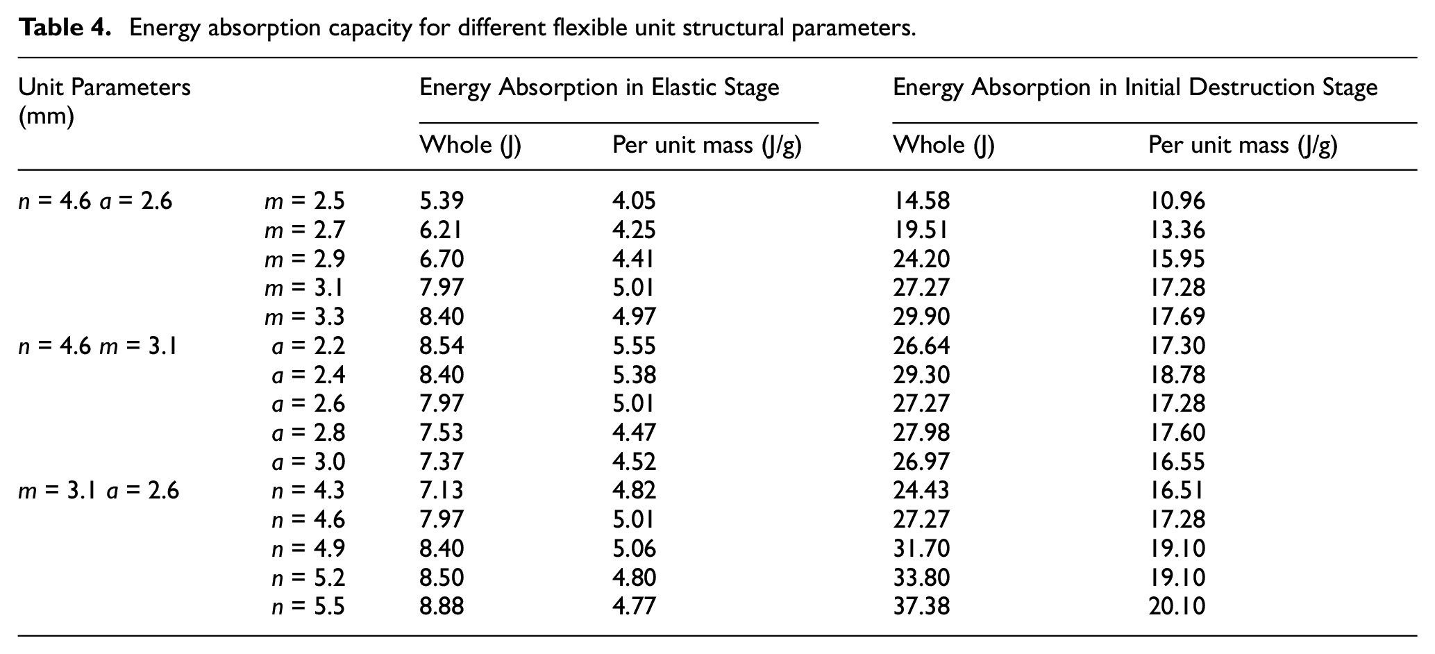
The following observations can be made from the results in Table 4:
With an increase in the structural parameter m, the overall energy absorption capacity of the unit increases, and the energy absorption capacity per unit mass also increases. When m increases from 2.5 mm to 3.3 mm, the energy absorption capacity in the unit’s elastic deformation stage increases by 3.01 J, the energy absorption capacity per unit mass in the elastic stage increases by 0.92 J/g, the energy absorption capacity at the initial failure increased by 15.32 J, and the energy absorption capacity per unit mass at the initial failure increased by 6.73 J/g.
With an increase in the structural parameter a, the energy absorption capacity of the unit in the elastic deformation stage is reduced, and the energy absorption capacity per unit mass in the elastic stage is also reduced. A change in a has little effect on the unit’s initial damage energy absorption capacity.
With an increase in the structural parameter n, the energy absorption capacity of the unit during the elastic deformation stage and initial destruction stage increases, but n has less influence on the energy absorption ability of the unit during the elastic deformation stage. When n increases from 4.3 mm to 5.5 mm, its energy absorbed during the elastic deformation stage only increased by 1.75 J, and there was almost no change in absorbed energy per unit mass. The value of n mainly affects the unit in its yield stage.
Figure 10 shows the compression characteristics of the flexible unit with different structural parameters. As shown in Figure 10(a), when m and n are constant, the change of a has little effect on the mechanical properties of the unit. As a increases, the element’s yield strength and elastic modulus decrease slightly. For example, when a increases from 2.4 mm to 2.8 mm, the elastic modulus of the cell decreases from 3.32 GPa to 3.22 GPa, and the yield strength decreases from 259 MPa to 243.2 MPa.

Compression characteristics of the flexible unit and Kagome Structure: (a) flexible unit with m = 3.1 mm, n = 4.6 mm and a = 2.2–3.0 mm; (b) flexible unit with m = 3.1 mm, a = 2.6 mm and n = 4.3–5.5 mm; (c) flexible unit with n = 4.6 mm, a = 2.6 mm and m = 2.5–3.3 mm; (d) Kagome structure (four samples with support diameter d = 1.2 mm and inclination angle θ = 60°).
As shown in Figure 10(b), when m and a are fixed, the strength and elastic modulus of the unit increase with increasing n. For example, when n increases from 4.6 mm to 5.2 mm, the yield strength of the unit increases from 243.2 MPa to 265.6 MPa, and the modulus of elasticity increases from 3.2 GPa to 3.65 GPa.
Figure 10(c) shows that when n and a are fixed values, the strength and elastic modulus of the unit also increase with increasing wall thickness m, and the increase is larger than that of the width. For example, as m increases from 2.7 mm to 3.1 mm, the element’s yield strength increases from 198.4 MPa to 243.2 MPa, and its modulus of elasticity increases from 2.65 GPa to 3.2 GPa.
Performance comparison of the flexible unit and Kagome structure
The compression performance curve of the Kagome structure is shown in Figure 10(d). The yield stress of the Kagome structure is about 28.51 MPa, and the yield displacement is about 3.6 mm. The energy absorbed during the elastic deformation stage is approximately 0.80 J, and the energy absorbed during the initial failure is approximately 2.73 J.
Table 5 compares the mechanical properties and energy absorption capacity per unit mass between the flexible unit with structural parameters a = 2.2 mm, m = 3.1 mm, and n = 4.6 mm and the Kagome structure. The elastic modulus of the flexible unit is 45.56% lower than the Kagome structure, but the flexible unit is 36.11% higher in yield strength, 39.10% higher in absorbed energy in the elastic deformation stage, and 26.83% higher in absorbed energy in the initial destruction stage. In short, the flexible unit has higher yield strength and energy absorption capability than the Kagome structure.
Comparison between the flexible unit with a = 2.2 mm, m = 3.1 mm, n = 4.6 mm and the Kagome structure.

Conclusion
This paper presents a flexible unit that can absorb a large amount of energy during the elastic deformation stage. Flexible units with different structural parameters are made using selective laser melting (SLM) technology, and comparative compression tests of the flexible units and the Kagome structure are carried out. The test results show:
With structural parameters a = 2.6 mm, m = 3.1 mm, and n = 5.5 mm, the energy absorption capacity of the unit in the elastic deformation stage is the highest, and the energy absorption capacity at the time of damage is also the best.
Within the range of manufacturability of SLM technology, increasing parameters m and n and decreasing parameter a of the flexible unit can improve its energy absorption capacity in the elastic deformation stage.
The flexible unit has higher yield strength and energy absorption capacity than the Kagome structure. At the same mass, the elastic modulus of the elastic damping element is 45.56% lower than the Kagome structure, but the element has a 36.11% higher yield strength, a 39.10% higher absorbed energy in the elastic deformation stage, and a 26.83% higher absorbed energy at initial destruction.
Therefore, the flexible unit has excellent energy absorption capability while ensuring the strength of the parts. In the elastic deformation stage, it has energy absorption performance unmatched by other unit structures. When the flexible unit is applied to the interior of a part, it can allow the part to absorb a large amount of energy without yielding and becoming damaged and greatly improves its performance and application, providing advanced application value in the field of machinery.
Footnotes
Handling editor: Chenhui Liang
Declaration of conflicting interests
The authors declare no potential conflicts of interest with respect to the research, authorship, and/or publication of this article.
Funding
The work was supported and financed by the National Natural Science Foundation of China (No.51875571) and the Natural Science Foundation of Hunan Province (No. 2020JJ6091).