
Abstract
In order to improve the accuracy of trajectory tracking of in-wheel motor electric vehicles, a preview time adaptive trajectory tracking method based on iterative algorithm and fuzzy control is proposed. Firstly, based on the vehicle’s three-degree-of-freedom model, the vehicle is controlled to track trajectory based on model predictive control (MPC). The preview step size and sampling period of MPC are adjusted by iterative function and fuzzy controller, respectively. Then, In order to optimize MPC active steering control, a differential torque controller is established to realize the trajectory tracking control of differential torque steering. Finally, Carsim/Simulink co-simulation analysis and real vehicle verification are done. The simulation results show that the controller can complete the trajectory tracking control of the in-wheel motor intelligent vehicle, and the stability and steering performance are good. The controller has good robustness and adaptability according to road adhesion conditions and vehicle speed changes. At the same time, the trajectory tracking accuracy of the MPC controller is better than sliding mode variable structure control (SMC). The real vehicle verification results show that when the real vehicle tracking under different speeds, the adaptive preview time controller designed in this paper has good trajectory tracking performance and stability.
Keywords
Preface
At present, people’s demand for automobiles is increasing. In response to the environmental pollution caused by automobile emissions and the increase in the number of traffic accidents caused by the rapid increase of vehicles, countries around the world are vigorously promoting vehicle electrification and vehicle intelligence. 1 However, due to lack of verification of vehicle safety and dynamics control of existing in-wheel motor-driven electric vehicles, most of them can only be simulated and analyzed. 2 In-wheel motor-driven electric vehicles can enhance the dynamic control of electric vehicles through the estimation of vehicle conditions and parameters and the study of driver’s driving characteristics. At the same time, trajectory tracking control has become the research focus of intelligent vehicles. 3 Luan et al. 4 proposed an adaptive model predictive control algorithm to solve system instability in order to improve the tracking accuracy, robust stability and calculation efficiency in the rolling optimization process, this algorithm can suppress random network delays and improve the safety of autonomous driving systems. He et al. 5 proposed a trajectory tracking control method based on the deep deterministic strategy gradient algorithm in reinforcement learning for the problem of lateral control, the results show that the method has small lateral deviation and angular deviation in the process of trajectory tracking control, and can meet the tracking requirements under different vehicle speeds. Xu et al. 6 used optimal control to plan human-like trajectories in consideration of the natural comfort of passengers to reflect natural driving behavior, thereby improving the acceptability of future unmanned vehicles. Yang et al. 7 compared the model predictive control and robust H∞ state feedback control of trajectory tracking under different driving conditions. Zhang et al. 8 proposed an active rear steering vehicle path tracking control method that considers the driver’s steering characteristics based on the MPC controller, to help the driver track the desired trajectory in a customized way, reduce the driver’s workload. Wu et al. 9 designed a linear time-varying model predictive trajectory tracking controller by locally linearizing the nonlinear vehicle model, and considered the vehicle dynamic stability constraints. The preview time used in the model predictive control in the above documents is a fixed value, which cannot be applied to the requirements of driving under different working conditions. Xie et al. 10 and Zhou et al. 11 have done research on the adaptive adjustment of preview time, but the factors are considered less, parameter adjustment is more cumbersome. Yu and Liao 12 and Yu and Li 13 studied the problem of observer-based predictive tracking control, and then designed a new predictive control scheme for the trajectory tracking problem of continuous-time nonlinear systems. At the same time, the vehicle has less emphasis on torque difference control during steering. Hu et al. 14 proposed a torque distribution control strategy that adapts to different driving speeds, which improves the steering maneuverability of the vehicle at low speeds and achieves steering stability at high speeds. Man and Zhao 15 established an electric vehicle model with independent front-wheel drive, the electronic differential control strategy of driving wheel equal power distribution is constructed, but the control system was only verified by simulation in Matlab, without considering the real-time nature of the control system. Jin et al. 16 coordinated the control of four-wheel independent drive and four-wheel independent steering, but did not consider the changes in road attachment conditions.
This paper proposes an MPC trajectory tracking control method based on adaptive preview time. The innovation of this paper is mainly reflected in the simultaneous and real-time control of the preview step and simulation period in MPC. The preview step length is adjusted by setting an iterative function in the S function, and the simulation cycle is adjusted by setting up a fuzzy control module outside the S function, which reduces the complexity of adaptive adjustment of the preview time and improves the real-time performance. In addition, in order to optimize the active steering control, the differential torque control is considered when the vehicle is turning.
The rest of the paper is organized as follows: chapter 2 introduces the vehicle dynamics model; Chapter 3 introduces the trajectory tracking control method based on improved MPC; Chapter 4 introduces simulation and real vehicle verification under multiple conditions; Finally, Chapter 5 summarizes this research.
Vehicle model
In order to achieve trajectory tracking, dynamic analysis of the vehicle is required. By considering vehicle stability, ignoring vehicle suspension characteristics, and considering the real-time requirements in model predictive control, the vehicle dynamics model is established as shown in Figure 1. In the Figure 1, the vehicle coordinate system is oxyz, and the inertial coordinate system is OXY. The vehicle only moves in three degrees of freedom: longitudinal, lateral, and yaw. Flf and Flr are the longitudinal forces received by the front and rear tires respectively; Fcf and Fcr are the lateral forces received by the front and rear wheels respectively; Fxf and Fxr are the forces received by the front and rear wheels in the x direction respectively; Fyf and Fyr are the forces received by the front and rear wheels respectively force in the y direction. The force balance equations of the vehicle along the x-axis, y-axis, and around the z-axis are as follows:


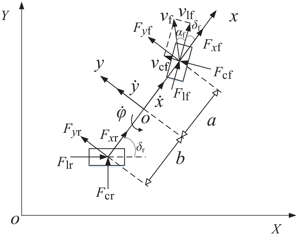
Simplified vehicle dynamics model.
where, m is the curb weight of the vehicle, φ is the yaw angle of the vehicle, Iz is the moment of inertia around the z-axis, and a and b are the distances from the center of mass to the front axles and rear axles, respectively.
The car body coordinate system and inertial coordinate system used in modeling, the conversion relationship between the two is:


Assuming that the tire deflection angle works in a small angle range, the tire longitudinal force and lateral force can be obtained:


where, Cl and Cc are the longitudinal and lateral stiffness of the tire, s is the slip rate, and α is the side slip angle of the tire.
After simplification and derivation, the nonlinear vehicle dynamics model is obtained as:

where, δf is the steering angle of the front wheels.
Improved MPC trajectory tracking control method
Trajectory tracking control framework
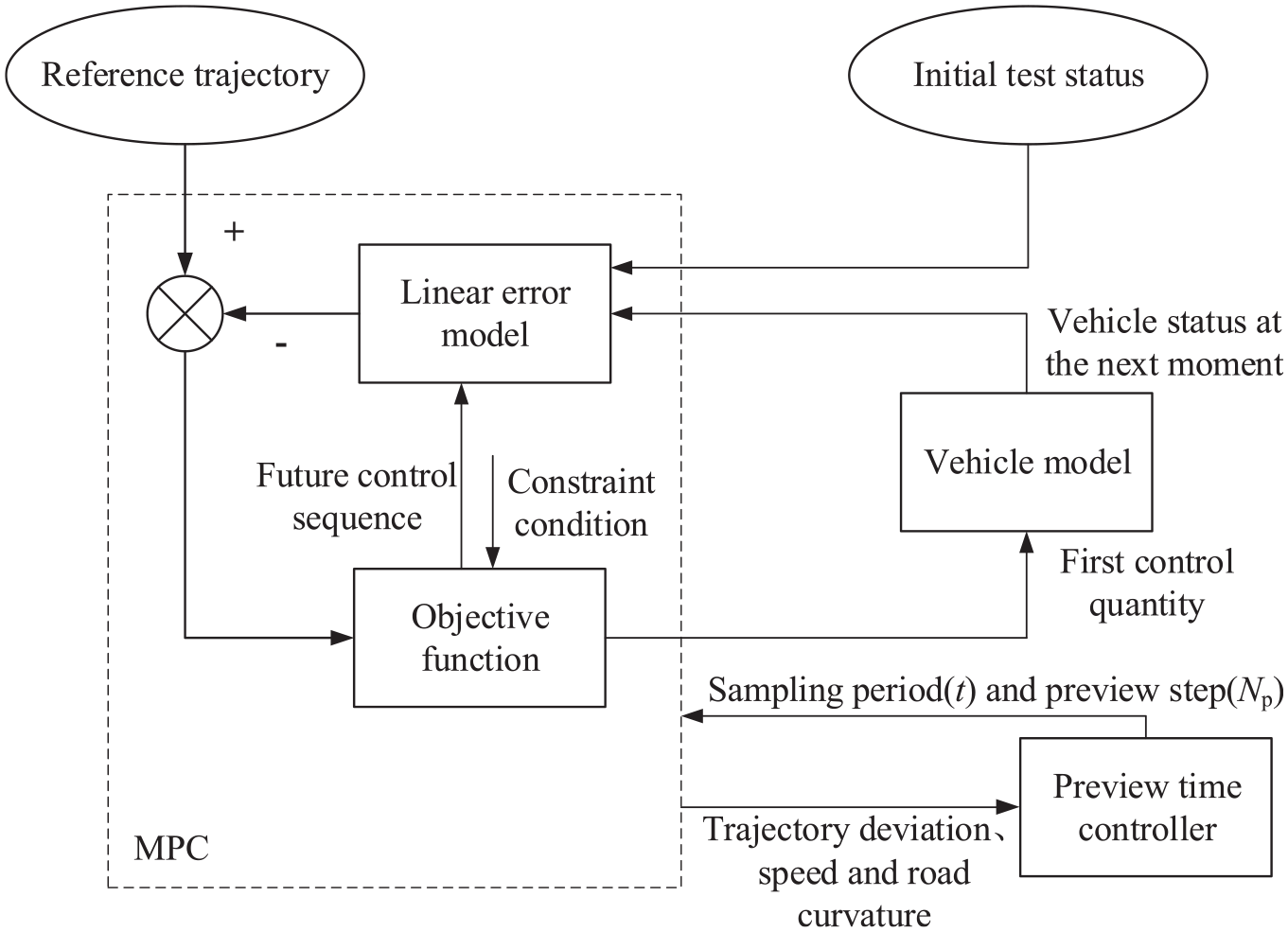
The framework of the trajectory tracking method is shown in Figure 2. Firstly, based on the vehicle’s three degree of freedom model, the vehicle is controlled to track trajectory based on model predictive control (MPC). Then use iterative function and fuzzy controller to adjust the preview step length and sampling period of MPC to realize adaptive control of preview time. Finally, a differential moment controller is established with the center of mass slip angle as the control target, the trajectory tracking control under differential torque steering is realized.

Framework structure of trajectory tracking method.
Basic MPC algorithm
The vehicle dynamics model (8) can be expressed as:amutha
where, the state quantity is defined as

where,
The approximate discretization of the first-order difference quotient is adopted, namely:

Among them, I is the identity matrix and T is the sampling period. Combining equations (10) and (11), we can get:

Considering the design of the MCP controller, equation (12) can be transformed into:

where,
The role of the controller is to control the vehicle to track the desired trajectory quickly and smoothly, so the controller also adds soft constraints. 17 The objective function form adopted by the model prediction tracking controller is as follows:

where,
To solve the optimization problem, the objective function is expressed in quadratic form as:

where,
In the actual working process of the control system, some control variables and control increment constraints must be met. The constraints are set as follows:
(1) Control amount constraints

(2) Control incremental constraints

The variable to be solved in the objective function is the control increment, so the constraint condition should be given in the form of the control increment or the multiplication of the control increment and the conversion matrix. Convert the control increment constraint as follows:

Assume


where,

After completing the above solution in each control cycle, a series of control input increments and relaxation factors in the control time domain will be obtained as shown in the following formula:
Then use the first element of the control sequence as the actual control input increment to act on the system, namely:

After entering the next control cycle, repeat the above process to realize the trajectory tracking control based on the vehicle dynamics model. Since the center of mass slip angle has a greater impact on vehicle stability, a reasonable design of the center of mass slip angle constraint can improve the safety of MPC tracking control. In this paper, according to the enterprise standard, the center of mass slip angle

Considering the driving stability of the vehicle, set the front wheel slip angle

MPC algorithm based on preview time adaptive
In the MPC controller, the preview time is generally set to a constant value between 0.3 and 1.6, when the vehicle is at a high speed and complex trajectory, the fixed preview time will affect the tracking accuracy, so the preview time should be set adjustments according to road conditions to avoid large vehicle tracking errors. In order to achieve the above optimization goals, a preview time adaptive controller based on iterative algorithm and fuzzy control is designed. Figure 3 shows the preview time adaptive control strategy. The control strategy mainly includes two parts: the model predictive trajectory tracking controller and the preview time adaptive controller. The model predictive controller is the upper control system, which calculates the front wheel angle of the dynamic model according to the objective function and transmits it to the vehicle model; The preview time adaptive controller takes road curvature, trajectory deviation and vehicle speed as input, and uses iterative algorithm and fuzzy controller to solve the appropriate preview step and sampling period respectively, and inputs it to the model predictive controller to achieve preview time adaptive control.
Preview time adaptive control strategy.
The preview time T in MPC is equal to the product of the preview step size Np and the sampling period t, the preview time can be controlled by adjusting Np and t. The preview step Np is adjusted by referring to the rate of change of trajectory curvature, and the road curvature is obtained in real time during the simulation process, and the calculation formula is as follows:
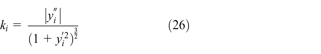
where,
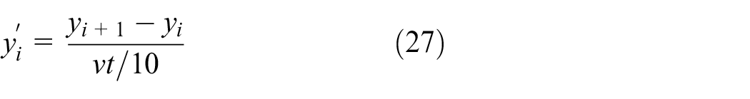
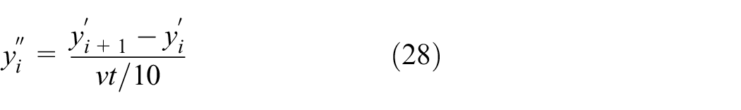
according to the formula (26), the rate of change of the curvature of the reference trajectory

where, yi is the ordinate of the MPC preview vehicle trajectory at the ith moment,
Through the prediction characteristics of MPC, using p as the evaluation index, judge the characteristics of the trajectory within the next preview distance of the current position:

p and Np can be expressed by a cubic polynomial:

where, the initial value of Np is 20, and the values of c1, c2, and c3 are 11.34, 2.37, and −1.6, respectively.
The sampling period t is adjusted by the track deviation e and the road curvature k. The trajectory deviation e and the road curvature k are used as the input of the fuzzy controller, and the sampling period t is calculated as the output, and it is input to the fuzzy controller in real time. The vehicle trajectory deviation and road curvature are normalized, and the trajectory deviation parameter E and the road curvature parameter K are shown in the following formula:
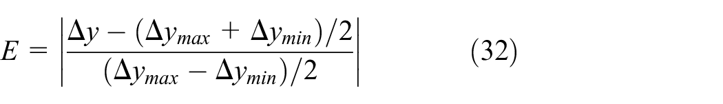
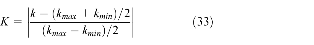
where,
Suppose the domains of E and K are both [0, 1], classify them into {0, 0.25, 0.5, 0.75, 1}, and the corresponding fuzzy set is {VL, L, M, H, VH}. The sampling period t is taken as the output of the fuzzy controller, and its parameter is set to T, the range is {0.03, 0.04, 0.05, 0.06, 0.07}, corresponding to {VL, L, M, H, VH}. The designated fuzzy rules are shown in Table 1. After the fuzzy control calculation, the sampling period t, the trajectory deviation E, and the road curvature K are shown in Figure 4.
Fuzzy rules.


Control rules of track deviation and road curvature.
Through MPC trajectory tracking controller, the tracking effect of the adaptive preview time and fixed preview time is compared and verified. The trajectory tracking effect at the vehicle speed of 72 km/h is shown in Figure 5(a). When the adaptive preview time MPC is used, the maximum lateral deviation between the vehicle trajectory and the reference trajectory is 0.99 m, and the root mean square of the lateral deviation is 0.23 m. When the fixed preview time MPC is used, the maximum lateral deviation between the vehicle trajectory and the reference trajectory is 1.25 m, and the root mean square of the lateral deviation is 0.36 m. It can be seen from the Figure 5 that the trajectory tracking accuracy can be improved better by using the adaptive preview time than by using the fixed preview time when turning. The trajectory tracking effect at the speed of 108 km/h is shown in Figure 5(b). When the adaptive preview time MPC is used, the maximum lateral deviation between the vehicle trajectory and the reference trajectory is 2.28 m, and the root mean square of the lateral deviation is 0.37 m. When the fixed preview time MPC is used, the maximum lateral deviation between the vehicle trajectory and the reference trajectory is 2.41 m, and the root mean square of the lateral deviation is 0.83 m. It can be seen from the Figure 5 that the tracking accuracy of the tracking trajectory using adaptive preview time MPC is slightly reduced after turning, but the tracking effect is better when driving in a straight line. In addition, the stability of the vehicle is higher, and the overall trajectory tracking accuracy is improved.

Track tracking effect: (a) the vehicle speed is 72 km/h and (b) the vehicle speed is 108 km/h.
The simulation result of vehicle speed 72 km/h and preview time is shown in Figure 6(a). It can be seen from the figure that the preview time decreases when the road curvature is large, and the preview time at the maximum road curvature is as low as 0.43 s, when the curvature of the second half of the trajectory is small, the preview time is increased to 0.75 s, and the driving stability of the vehicle is improved. The simulation result of preview time at a speed of 108 km/h is shown in Figure 6(b). It can be seen from the figure that due to the increase in vehicle speed, the preview time is constantly adjusted at the place where the road curvature is larger, and the preview time can respond to increase when the curvature is smaller, this shows that the designed controller can meet the requirements of preview time adaptation.

Preview time simulation results: (a) the vehicle speed is 72 km/h and (b) the vehicle speed is 108 km/h.
Coordinated control of torque difference and MPC
Since the in-wheel motor intelligent vehicle cancels the differential transmission of the traditional vehicle, it is also necessary to consider the differential torque of the steering wheel in the trajectory tracking control, it is known that the side slip angle of the center of mass plays a key role in the stability of the vehicle steering. 19 Therefore, a fuzzy controller with the mass slip angle as the control target and the inner and outer wheel torque adjustments as the output is proposed, it is used to adjust the torque difference when turning.
The error
Determine the domain of input and output parameters. The domain of the mass center slip angle error e and the mass center slip angle error derivative ec is [−6, 6]; the torque adjustment amount ΔT domain is [−100, 100]. The fuzzy sets of e, ec, and ΔT are all {NB, NM, NS, ZE, PS, PM, PB}, the designated fuzzy rules are shown in Table 2, and the input-output relationship after fuzzy calculation is shown in Figure 7.
Fuzzy rules.


Input output relationship.
Based on the above theory, the vehicle model’s torque difference verification is carried out under Simulink/CarSim. Given a vehicle speed of 10 m/s, the road attachment condition is set as the ideal dry road μ = 0.8, and the double shifting working condition is set. Figure 8 shows the center of mass slip angle. It can be seen from the figure that the center of mass slip angle changes smoothly during the simulation, the vehicle is in good driving condition, there is no rollover or instability, and the vehicle has good stability during driving. Figures 9 and 10 show the torque difference output by the differential torque controller and the inner wheel torque, respectively. It can be seen from the figure that the torque difference output by the torque difference controller and the left wheel torque are adjusted with the change of the side slip angle of the center of mass, the torque difference fluctuates at the larger curvature, but the torque output quickly tends to smooth. When the side slip angle of the center of mass fluctuates greatly, the wheel differential torque follows the change, indicating that the designed differential torque controller can complete the role of differential driving.

Centroid deflection angle at 10 m/s.

Output torque difference.

Inner wheel differential torque.
Simulation and test verification
In order to verify the effectiveness of the proposed control system, Matlab/Simulink and Carsim are used to build a joint simulation platform to carry out a simulation experiment of two-lane change trajectory tracking. In Carsim, the vehicle model is changed to four-wheel independent drive, and the power is introduced by Simulink.
Trajectory tracking comparison verification
In order to achieve the comparison of trajectory tracking performance, the sliding mode variable structure control (SMC) algorithm is introduced and compared with MPC for verification.
Scene A
Set the vehicle speed to 90 km/h and the road friction coefficient to 0.8. The simulation result of scenario A is shown in Figure 11. Figure 11(a) and (b) show the simulation results of the trajectory and heading angle of the two controllers. When using the MPC controller, the maximum lateral deviation between the vehicle trajectory and the reference trajectory is 1.44 m, and the root mean square of the lateral deviation is 0.25 m; the maximum deviation between the heading angle and the desired heading angle is 7.50°, and the root mean square of the deviation is 1.38°. When using the SMC controller, the maximum lateral deviation between the vehicle trajectory and the reference trajectory is 2.31 m, and the root mean square of the lateral deviation is 0.79 m; the maximum deviation between the heading angle and the desired heading angle is 14.86°, and the root mean square of the deviation is 5.71°. It can be seen that in this case, the trajectory tracking accuracy of the MPC controller is better than that of the SMC controller. Figure 11(c) shows the front wheel angles under the two controllers. The maximum front wheel angle controlled by MPC is 2.18°, while the maximum front wheel angle controlled by SMC is 3.82°, it shows that the output steering angle of the MPC controller is small and the change is stable. Figure 11(d) shows the center of mass slip angle under the action of two controllers. The maximum value of the center of mass slip angle controlled by MPC is 1.38°, and the maximum value of the center of mass slip angle controlled by SMC is 1.88°, both of which are smaller than the limit constraint.
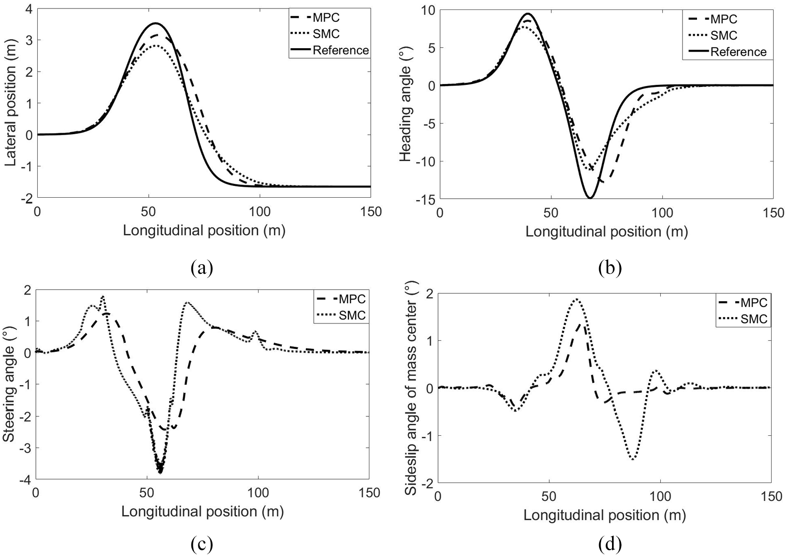
Simulation results of scenario A: (a) trajectory, (b) heading angle, (c) steering angle, and (d) sideslip angle of mass center.
Scene B
The vehicle speed is set to 108 km/h, the road friction coefficient is 0.8, and the simulation result of scenario B is shown in Figure 12. Figure 12(a) and (b) show the trajectory and heading angle simulation results of the two controllers. When using the MPC controller, the maximum lateral deviation between the vehicle trajectory and the reference trajectory is 2.28 m, and the root mean square of the lateral deviation is 0.37 m; the maximum deviation between the heading angle and the desired heading angle is 9.71°, and the root mean square of the deviation is 1.78°. When using the SMC controller, the maximum lateral deviation between the vehicle trajectory and the reference trajectory is 2.57 m, and the root mean square lateral deviation is 0.90 m; The maximum deviation between the heading angle and the desired heading angle is 16.18°, and the root mean square of the deviation is 5.12°. It can be seen that in this case, the trajectory tracking accuracy of the MPC controller is better than that of the SMC controller. Figure 12(c) shows the front wheel angles under the two controllers. The maximum front wheel angle controlled by MPC is 2.37°, while the maximum front wheel angle controlled by SMC is 5.47°, it shows that the output steering angle of the MPC controller is small and the change is stable. Figure 12(d) shows the center of mass slip angle under the action of two controllers. The maximum value of the center of mass slip angle controlled by MPC is 4.18°, and the maximum value of the center of mass slip angle controlled by SMC is 4.76°, both of which are smaller than the limit constraint.

Simulation results of scenario B: (a) trajectory, (b) heading angle, (c) steering angle, and (d) sideslip angle of mass center.
Trajectory tracking performance verification
Trajectory tracking of double line shifting at different vehicle speeds
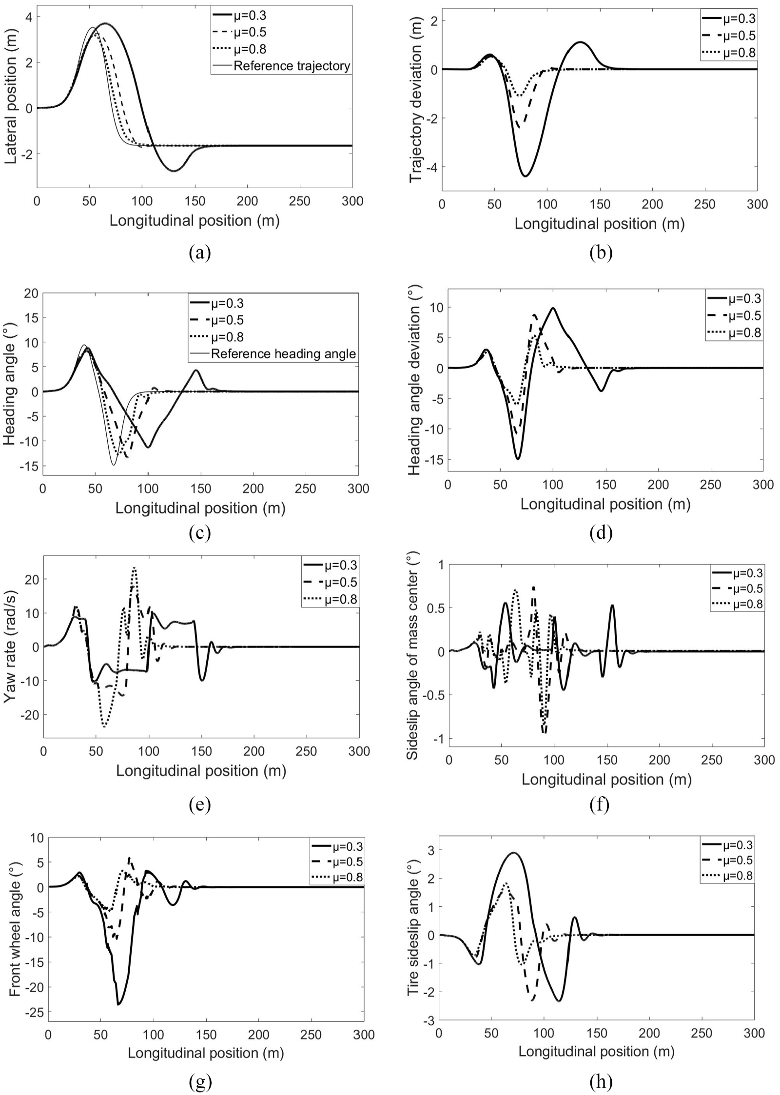
Set three longitudinal vehicle speeds of 20 m/s (72 km/h), 25 m/s (90 km/h), 30 m/s (108 km/h) to track the double line trajectory, and set the simulation time to 20 s, the simulation step is 0.001, and the road attachment condition is the ideal dry road μ = 1. The simulation result is shown in Figure 13. Figure 13(a) and (b) show the tracking trajectory and trajectory deviation of the vehicle respectively. It can be seen from Figure 13(a) and (b) that the vehicle can track the target trajectory under three different speed conditions, and the tracking error increases with the increase of vehicle speed, and the position error is more obvious in the larger curvature. Figure 13(c) and (d) are the heading angle and heading angle deviation of the vehicle respectively. From Figure 13(c) and (d), it can be seen that the heading angle changes smoothly at various speeds, with the increase of vehicle speed, the heading of the vehicle also changes in advance, and the heading angle deviation also changes with the increase of vehicle speed.

Simulation results of different vehicle speeds: (a) trajectory, (b) trajectory deviation, (c) heading angle, (d) heading angle deviation, (e) yaw rate, (f) sideslip angle of mass center, (g) front wheel angle, and (h) tire sideslip angle.
Figure 13(e) and (f) are the vehicle’s yaw rate and center of mass side slip angle, respectively. It can be seen from Figure 13(e) and (f) that the vehicle’s yaw rate changes smoothly following the vehicle trajectory, and fluctuates when the vehicle turns, the center of mass slip angle changes smoothly when the vehicle speed is low, and its amplitude reaches −4.18° and 3.52° when the vehicle speed is 30 m/s, this is because the stability is slightly reduced due to the high speed. According to the formula (24), it is known that on dry standard road surface, the center of mass slip angle
Based on the above tracking results at different speeds, the tracking accuracy of the vehicle decreases to a certain extent with the increase of speed, but the various parameters of the vehicle meet the constraint requirements, and the controller has good trajectory tracking performance and strong robustness to speed.
Double line shifting trajectory tracking under different road attachment conditions
Aiming at the three road conditions of dry, slippery and snowy roads, the vehicle trajectory tracking ability was tested under the three conditions of adhesion coefficient μ = 0.3, 0.5, and 0.8. The longitudinal speed of the vehicle is set to 20 m/s (72 km/h), the simulation time is 20 s, and the simulation step is 0.001. The simulation results under different attachment conditions are shown in Figure 14.
Simulation results under different adhesion conditions: (a) trajectory, (b) trajectory deviation, (c) heading angle, (d) heading angle deviation, (e) yaw rate, (f) sideslip angle of mass center, (g) front wheel angle, and (h) tire sideslip angle.
Figure 14(a) and (b) show the tracking trajectory and trajectory error of the vehicle respectively. It can be seen from Figure 14(a) and (b) that the vehicle has better trajectory tracking performance in an environment with a good road adhesion coefficient, when the road environment is poor (μ = 0.3), although the trajectory tracking can be completed, the trajectory tracking performance becomes worse and the tracking error increases. Figure 14(c) and (d) are the heading angle and heading angle deviation of the vehicle, respectively. It can be seen from Figure 14(c) and (d) that the heading angle of the vehicle changes smoothly at the 100–150 m longitudinal trajectory. When μ = 0.3, the heading angle deviation has a peak value, with the increase of the road adhesion coefficient, the actual heading angle is getting closer to the reference value. Figure 14(e) and (f) are the vehicle’s yaw rate and center of mass side slip angle, respectively. It can be seen from Figure 14(e) and (f) that the vehicle’s yaw rate and center of mass side slip angle change smoothly, when μ = 0.3, the yaw rate continues for a short time at a certain angle, and the side slip angle of the vehicle’s center of mass is still partially fluctuating at 150 m in the longitudinal trajectory due to the poor road environment, and its amplitude reaches −0.95° and 0.74° when μ = 0.5. According to the formula (24), it is known that on wet and slippery road surface, the center of mass slip angle
Combining the above tracking results under different attachment conditions, the vehicle is accompanied by better conditions, and the tracking error is getting smaller and smaller, on icy and snowy roads with poor attachment conditions, the yaw rate of the vehicle will be unstable to a certain extent, but the controller can make corrections in time, it shows that the controller has good trajectory tracking performance under different attachment conditions, and has good robustness to different road environments.
Comparing the simulation results of the above two working conditions, the controller can complete the trajectory tracking control of the in-wheel motor intelligent vehicle, and has good robustness and adaptability to road attachment conditions and vehicle speed changes.
Real vehicle verification
An intelligent electric vehicle is used in the experiment, an integrated navigation and CAN communication system are equipped and the vehicle is controlled through the vehicle controller. The actual vehicle system is shown in Figure 15. First, the vehicle is driven to produce a section of trajectory as the reference trajectory, and then the position information and steering wheel angle information in the integrated navigation through CAN communication during the experiment are collected. In order to verify the feasibility of the adaptive preview time trajectory tracking controller, a trajectory tracking test of low vehicle speeds under lane changing conditions is carried out.

Real vehicle system.
Scenario A
It is set to track the reference trajectory at two longitudinal vehicle speeds of 10 and 25 km/h. The test results of scenario A are shown in Figure 16. The tracking trajectory is shown in Figure 16(a). It can be seen from the Figure that the trajectory tracking accuracy at the two vehicle speeds is good. Although the deviation at the end of the trajectory tracking is slightly larger at the vehicle speed of 25 km/h, it can be tracked to the end of the trajectory. The heading angle and steering wheel angle of the vehicle are shown in Figure 16(b) and (c), respectively. It can be seen from the figure that, the heading angle deviation will increase as the vehicle speed increases. The heading angle and front wheel turning angle at 25 km/h both have a certain amplitude jump at the end, which is caused by the environmental influence of the target vehicle during the trajectory tracking process. However, the overall change is gentle. To sum up, the tracking accuracy of the vehicle decreases to a certain extent with the increase of speed, but the overall driving of the vehicle is stable, and the controller has good trajectory tracking performance.
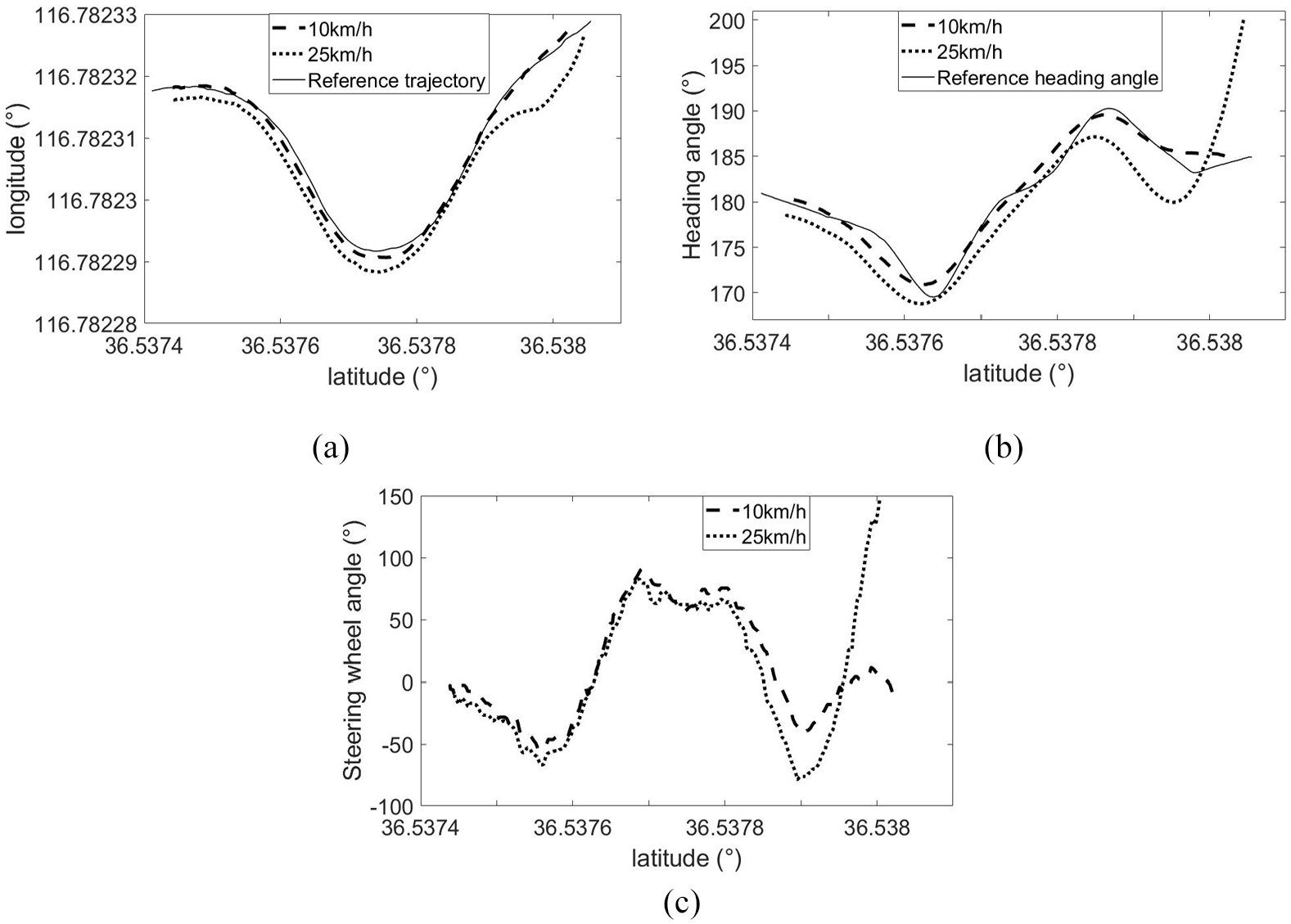
Scenario A test results: (a) trajectory, (b) heading angle, and (c) steering wheel angle.
Scenario B
An MPC trajectory tracking controller with fixed preview time is designed in Yuan. 20 This paper’s control method and literature 20 are compared and the control accuracy of this paper’s control method is verified through real vehicle test. The trajectory tracking real vehicle test is carried out at a vehicle speed of 10 km/h in the scenario B, and the test results of scenario B are shown in Figure 17. Figure 17(a) shows the tracking trajectory. It can be seen from the figure that compared to the fixed preview time, the driving trajectory under the adaptive preview time during steering is closer to the reference trajectory, and the tracking accuracy of the trajectory is improved. Figure 17(b) and (c) are the heading angle and steering wheel angle of the vehicle, respectively. It can be seen from the figure that the heading angle under adaptive control is generally closer to the reference value, and the heading deviation in the back section of the trajectory is smaller. At the same time, the steering wheel angle change under adaptive control is more in line with the reference heading angle, and the change is gentle at the end of the trajectory. In summary, the adaptive preview time can improve the stability of the vehicle when turning, and improve the accuracy of trajectory tracking.

Scenario B test results: (a) trajectory, (b) heading angle, and (c) steering wheel angle.
Conclusions
In this paper, a trajectory tracking method with improved MPC and torque difference control is proposed and tested. This improved MPC method can preview time adaptive control to improve the accuracy of trajectory tracking, and the torque difference control can coordinate trajectory tracking and improve the stability of vehicle driving. The content is summarized as follows:
(1) A model predictive control trajectory tracking algorithm based on adaptive preview time is proposed, which realizes adaptive control of the preview time of the model predictive controller through trajectory deviation, road curvature and vehicle speed. The preview time can be adjusted with multi-parameter according to different working conditions. Through simulation and comparison, it is found that the designed controller can meet the requirements of preview time adaptation, the preview time adaptive control strategy can improve the tracking accuracy and driving stability of the vehicle.
(2) The side-slip angle of the center of mass is used as a control variable, a differential torque controller based on fuzzy control is designed to adjust the torque of the inner and outer wheels when the vehicle is steered. Through simulation, it is verified that the differential torque controller can complete the function of differential driving, which ensures the stability of the vehicle under steering conditions.
(3) Multi-condition simulation verification and real vehicle test are carried out for the MPC trajectory tracking controller. The advantages of the MPC controller are compared and analyzed by simulation verification, and the results show that the controller has good steering performance and driving stability. The real vehicle verification results show that the adaptive preview time controller designed in this paper has good trajectory tracking performance, and the trajectory tracking of real vehicles at different speeds has good stability.
(4) In the follow-up research, the vehicle speed will be changed, and the trajectory tracking under dynamic vehicle speed will be considered in the control process.
Footnotes
Handling Editor: Chenhui Liang
Author contributions
Methodology and writing-original draft preparation, Wenyao Han; software and validation, Aijuan Li; writing-review and editing, Xin Huang and Aijuan Li.; Conceptualization, Wei Li; formal analysis, Haixiang Bu; Simulation and Analysis, Wenyao Han and Jiaoping Cao. All authors have read and agreed to the published version of the manuscript.
Declaration of conflicting interests
The author(s) declared no potential conflicts of interest with respect to the research, authorship, and/or publication of this article.
Funding
The author(s) disclosed receipt of the following financial support for the research, authorship, and/or publication of this article: This project is supported by National Natural Science Foundation of China (Grant No. 51505258 and 61601265), Shandong Provincial Natural Science Foundation, China (Grant No. ZR2015EL019, ZR2020ME126, and ZR2021 MF131), Shandong Province Higher Educational Youth Innovation Science and Technology Program (Grant No. 2019KJB019 and 2020KJN002), Open project of State Key Laboratory of Mechanical Behavior and System Safety of Traffic Engineering Structures, China (Grant No. 1903), Open project of Hebei Traffic Safety and Control Key Laboratory, China (Grant No. JTKY2019002), China Postdoctoral Science Foundation (Grant No. 2021M701405).