
Abstract
Hydraulic actuated quadruped robot has strong load capacity, good flexibility, and strong adaptability to complex environments. Pointing at the multi coupling and multi variable characteristics of hydraulic quadruped robot, this paper proposes a decomposed trajectory tracking control strategy based on model prediction for hydraulic quadruped robot. The tracking model is derived by the structure of the hydraulic quadruped robot. The inequality constraints of the quadruped robot motion are built. And the trajectory tracking control problem of the robot is transformed into a quadratic programing problem. The error model of the robot is built. Combining the minimization goals of robot motion speed and acceleration error, the stability and continuity constraints for robot motion are planned. The decomposed trajectory tracking controller with trajectory constraints is designed. The performance of proposed control method is verified by simulation and prototype experiment. The simulation and prototype comparative experiments of classical control strategy and the proposed control strategy are conducted on the hydraulic robot. The results show that compared with the traditional method, the motion trajectory error of the hydraulic robot is relatively small by the proposed optimal trajectory tracking control strategy. The rolling angle accuracy is ±0.066 rad, and the pitching angle accuracy is −0.073 to 0.044 rad. The effectiveness of the proposed control algorithm is verified by the simulation and experimental results. The accuracy of the hydraulic robot model in the control algorithm is improved, the impact during hydraulic robot motion is reduced, and the service life of the robot was increased, as well as the stability of robot motion is enhanced.
Introduction
With the development of artificial intelligence, human-computer interaction and other technologies, robots play an important role in aerospace, earthquake rescue, and other scenarios.1–3 Hydraulic actuated quadruped robots have strong load capacity, good flexibility, and strong adaptability to complex environments, with broad application prospects.4,5 The motion control of quadruped robot is the basic problem of robot system control. The trajectory tracking control problem is the focus of motion control research. And it is also a key technology for achieving intelligent control of robots. The trajectory tracking control of the robot can ensure that the actual trajectory track the desired trajectory, and improve the dynamic stability of the robot system.
It is unable to obtain the unknown environmental information for a quadruped robot in an unknown and complex environment. And it is difficult to describe the external interference of robot by an accurate mathematical model. In addition, due to the characteristics of underdrive, multivariable, strong coupling and nonlinearity, the trajectory tracking control performance of quadruped robot needs to be improved.
The trajectory tracking control methods of quadruped robot mainly include sliding mode control method,6,7 fuzzy control method,8–10 neural network control method,11–13 and so on. The above control methods have high computational efficiency. However, the chattering phenomenon will appear in the high frequency switching by using the sliding mode control method. The uncertainty of system parameters can be overcome by the fuzzy control method, but the control accuracy of the system will be affected by the chattering of the controller input. Neural network control method needs online learning, and its real-time performance is poor.
Furthermore, Bellicoso et al. 14 proposed an online real-time motion planning method based on zero moment point of quadruped robot. According to the contact time and the real-time state of the robot, the reference trajectory was constantly updated. The reference foothold of each leg of the robot was obtained by solving the optimization problem. A variety of gait movements and smooth switching between each gait were realized on the ANYmal quadruped robot platform.
The above control method only considers the output tracking of the robot system, and the impact of control increments on the system is ignored. The kinematic and dynamic constraints of robots are often ignored or simplified in traditional control algorithms.1,15,16 Such as constraints of motion position, constraints of motion speed, constraints of the joint speed, constraints of non-sliding of the foot, and so on. Nevertheless, these kinematic constraints typically have a significant impact on the stable motion of the robot.
The problems with multiple variables and constraints could be solved using model predictive control.17–19 By optimizing the objective function, the model predictive control algorithm could combine the kinematic constraints of the quadruped robot, and real-time online calculation can be carried out. The future output can be predicted according to the historical value and the current value of the system by model predictive control. And the model predictive control method has good anti-interference ability and tracking performance.
Carron et al. 20 proposed a trajectory tracking control method based on robot kinematics model, dynamics model and model predictive control. The linearized inverse dynamics feedback and error model of the manipulator were established. The residual interference was estimated online through the additional interference model, and the non-offset tracking of the manipulator was realized.
Grandia et al. 21 proposed a model predictive control method based on sequential linear quadratic programing for the optimal control of mobile robots. The robust solution was obtained according to the frequency cost function, which significantly improved the tracking performance of the kinematic trajectory, torque trajectory, and force trajectory of the ANYmal quadruped robot. Based on this, Grandia R et al. 22 proposed a model predictive feedback control method based on differential dynamic programing, which compensated the gap between the update rate of low model predictive control and the driving instruction. The sensitivity of the system to the high frequency model errors and actuator bandwidth constraints was reduced by the frequency dependent cost function. And the stable motion control of quadruped robot was realized by this method.
Minniti et al. 23 used the model predictive control method to optimize the balance and interaction of the unstable manipulator. The optimal control problem was transformed into the end effector space. The position and direction tasks were processed in the model predictive control planner, and the contact force of the end effector was planned. The effectiveness of the attitude tracking controller was proved by experiments. Neunert et al. 24 proposed a model predictive control method for the whole nonlinear contact rigid body system. A full dynamic system model including explicit contact dynamics was established. The contact position and order of quadruped robot system were calculated in real time by the model predictive controller. The validity and robustness of the proposed method were verified by the experiment of quadruped robot prototype.
As can be seen from the above research, the model predictive control method is an effective method to solve the trajectory tracking control problem of mobile robot. And the robustness of the robot control system can be improved.25,26 The combination of model predictive control method and other methods was used by some scholars to complete the control of robots.19,27,28 Villarreal et al. 29 combined convolutional neural networks with model predictive control methods to determine the locations of the foothold of the hydraulic quadruped robot HyQReal. Qin et al. 30 proposed a control method based on central pattern generator and model predictive control for quadruped robot, and the position tracking was achieved.
Furthermore, the MPC method can be used for short-term prediction and rolling optimization, and the model is re-linearized in each iteration to reduce the cumulative error caused by contact mutations. Through Lyapunov functions or constraint contraction theory, some studies have demonstrated that linearized MPC closed-loop systems can ensure the stability of the system under finite disturbances or the known contact sequence.31–34 And the robot system could demonstrate good performance. Such as, the robot dynamics were simplified to formulate the problem as convex optimization by Carlo et al. 35 Linearization error was alleviated by real-time state information feedback of the Cheetah3 robot.
However, there are currently few methods for trajectory control of hydraulic quadruped robots. The hydraulic quadruped robot system is complex, and the trajectory tracking accuracy of the foot end is affected by the position tracking accuracy of joint actuators.
In order to improve the accuracy and stability of the trajectory of quadruped robot, and restrain the influence of disturbance on the trajectory of robot, this paper proposed a decomposed trajectory tracking control strategy based on model predictive control. The tracking model and error model of quadruped robot are established. According to the inequality constraints in the motion process of quadruped robot, the trajectory tracking control problem is transformed into a quadratic programing problem. For the problem of disturbance rejection trajectory tracking control of quadruped robot, the trajectory tracking problem of the whole robot is divided into the trajectory tracking control problem of each foot end and the trajectory tracking control problem of the torso. The trajectory tracking target and constraint conditions of quadruped robot are established. The effectiveness of the algorithm proposed in this paper is verified through simulation and experiments.
Structural analysis and tracking model of hydraulic robot
Structure composition
The mechanical structure of a hydraulic quadruped robot is designed based on the structure of a quadruped mammal, consisting of a body and four bionic legs, as shown in Figure 1. The single leg has three active degrees of freedom, namely, yaw joint, hip joint roll, and knee joint. The motion pair between the thigh and the body is the yaw joint, the motion pair between the thigh and shank is the hip joint, and the motion pair between the ankle and shank is the knee joint. Linear bearings and shock-absorbing springs are installed between the knee joint and the foot end. And the shock-absorbing spring fixed on the shank leg of the robot is a passive degree of freedom. Each active joint is driven by the same electro-hydraulic servo actuator, which integrates a single rod hydraulic cylinder, electro-hydraulic servo valve, displacement sensor, and pressure sensor.
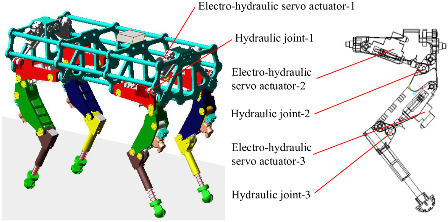
Simulation prototype of the hydraulic quadruped robot.
Tracking model
The position vector of quadruped robot in the inertial coordinate system is

In which,
In this paper, the trajectory tracking problem of robot is studied. The forward motion, lateral motion and yaw motion of robot are considered. The position and attitude vector of quadruped robot in inertial coordinate system is
The Jacobian matrix of a hydraulic quadruped robot is
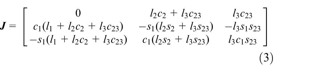
In which, l1,l2, and l 3 are the lengths of the hip link, thigh link and shank link, respectively. And θ1i, θ2i, and θ3i are joint angles of roll hip joint, pitch hip joint, and pitch knee joint, respectively. s1 = sinθ1, c1 = cosθ1, s23 = sin(θ2+θ3), c23 = cos(θ2+θ3), and the other angles are similar.
The dynamic equation of the quadruped mobile robot is as follows

Where,
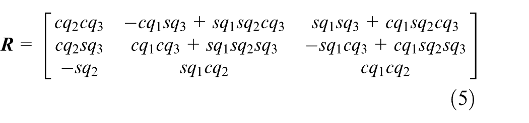
Where, sq3 = sin(q3), cq3 = cos(q3), and the other angles are similar.
The combined force and torque acting on the robot body are
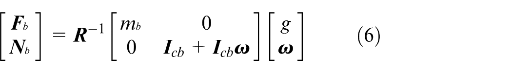
In which,
The dynamic equations of each link of the quadruped robot are as follows
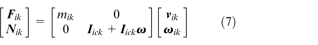
Where,
State space model
Error model
The simplification of the model will produce model error, and the robot will also produce model error when walking in unstructured or in unknown environment. When the hydraulic quadruped robot uses the established model to perform dynamic tasks, the unmodeled part will make the robot run with deviation, which will lead to the instability of the robot movement or failure to complete the specified tasks. Therefore, in order to improve the stability of the robot motion, it is necessary to establish an error model for the hydraulic quadruped robot.
The trajectory tracking control of the hydraulic quadruped robot is realized by controlling the moving speed in the forward direction, the moving speed in the lateral direction and the yaw speed of the robot. In order to track the desired trajectory of the robot, the error between the actual trajectory and the desired trajectory should be zero. The relationship between the actual and the expected position and attitude of the robot is

Where q(t) is the change of position and attitude with time of hydraulic quadruped robot, q d (t) the desired position and attitude of the hydraulic quadruped robot, e q (t) is the error between the expected and the actual position and attitude of the hydraulic quadruped robot.
When the motion time t of the hydraulic quadruped robot tends to infinity, the error between the desired pose and the actual pose of the robot should tend to zero.
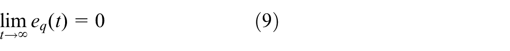
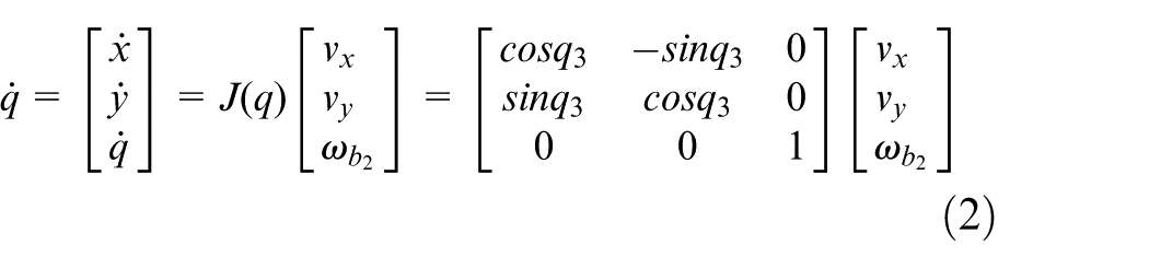
According to the kinematic model of the hydraulic quadruped robot, the input of the hydraulic quadruped robot system is u = [vx vyωbz]T, The state quantity is q = [x y q3]T, The state space expression of the hydraulic quadruped robot system is

Therefore, every point (qd, ud) on the reference trajectory of the hydraulic quadruped robot satisfies the following kinematic equation

Where q d = [xd yd q3d]T, u d = [vxd vydωbzd]T.
The first order Taylor expansion is performed at the reference point (q d , u d ) of the hydraulic quadruped robot
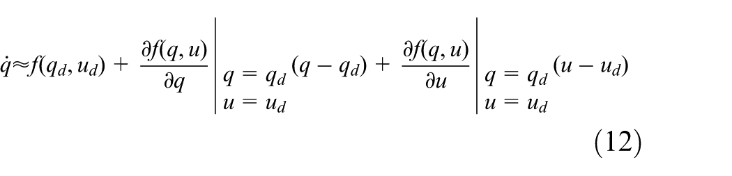
The linear error model of hydraulic quadruped robot can be obtained by combining equation (6) and equation (12), as follows
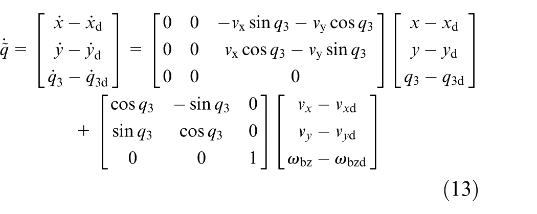
Equation (13) is discretized, and an augmented model based on the state space model is adopted. The form is as follows
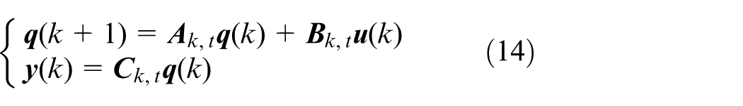
In which, the expression of
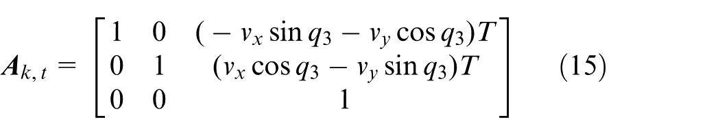
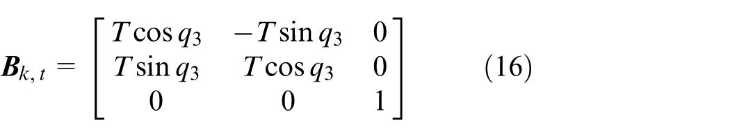
Where T is sampling time.
Performance index of controller
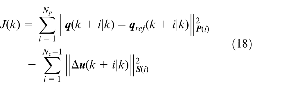
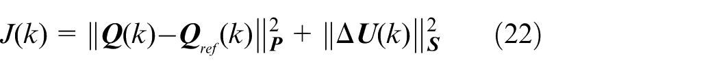
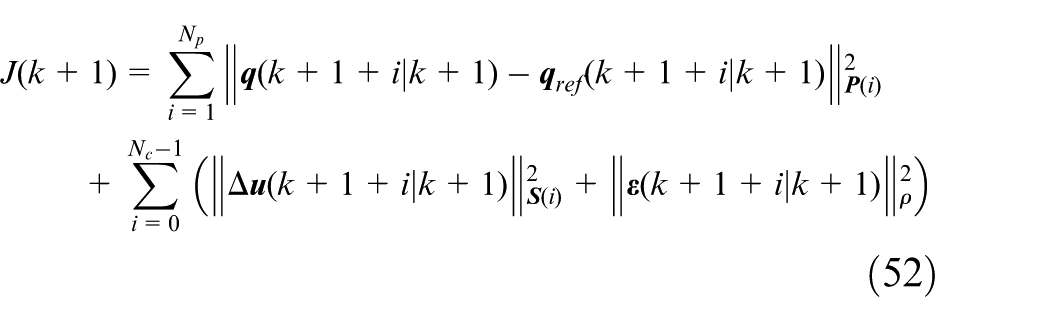
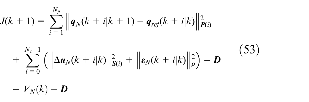
By setting a reasonable optimization target, the deviation between the motion track and the reference track of each joint of the hydraulic quadruped robot is minimized, and then the optimal control sequence is obtained. The objective function should ensure that the quadruped robot can track the desired trajectory quickly and stably. The form of the objective function is
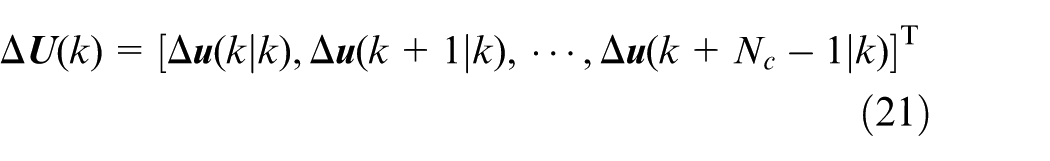
In which, N
c
is the control time domain,
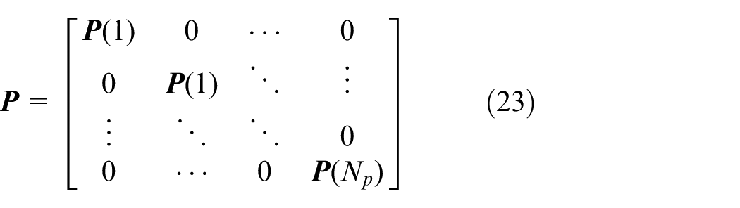
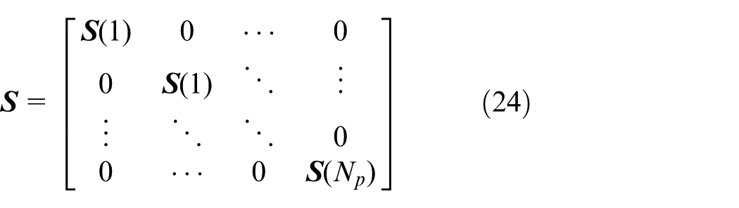
The definition matrices
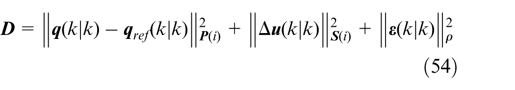
Combining equation (18)∼equation (21), equation (18) can be written as follows
Where
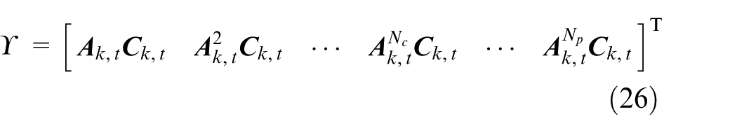
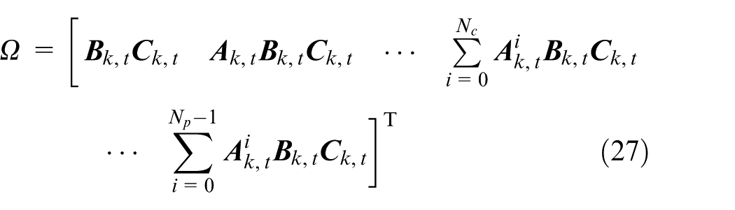
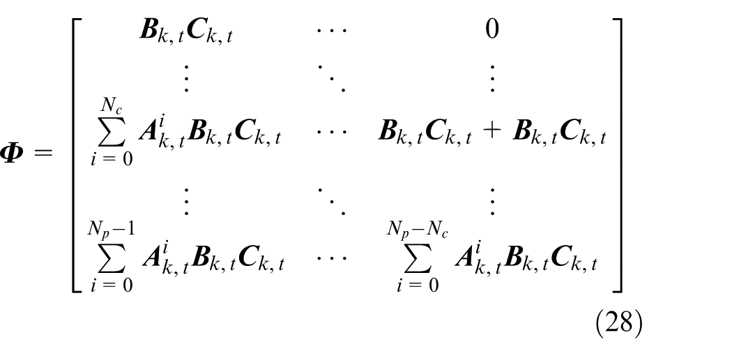
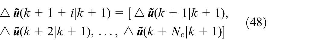
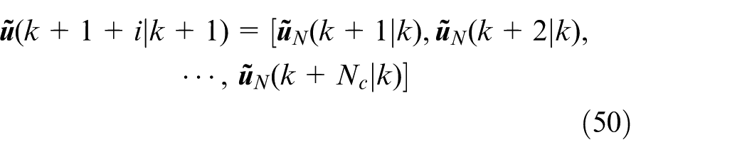
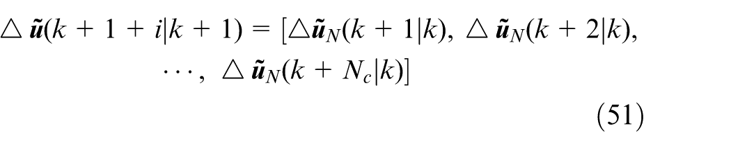
According to the linear kinematic model of the hydraulic quadruped robot, the predicted output of the quadruped robot system is

Where
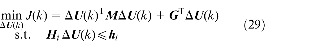
When the system model is linear and discrete, the optimal control problem in the predictive time domain of the model prediction control algorithm can be transformed into the optimal control problem in the finite time domain. The quadratic programing method is used to solve the optimal control sequence of a quadruped robot with multiple constraints, The form of quadratic programing problem is as follows
In which, Δ
According to the model of hydraulic quadruped robot, the following definitions are given
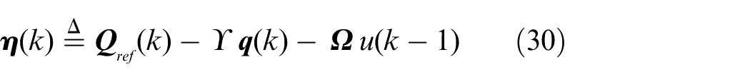
Combining equation (30), the objective function of hydraulic quadruped robot can be expressed as
According to the form of quadratic programing problem, the following definitions are given


Where, Г is a constant.
Combining equation (31) to equation (34), the objective function of the hydraulic quadruped robot can be expressed as

From equation (35), it can be seen that the objective function of the trajectory tracking of the hydraulic quadruped robot based on the model predictive control is transformed into the quadratic programing form of the input increment matrix Δ
Inequality constraints
In the control process of the hydraulic quadruped robot, due to the complexity of the robot working environment, the input constraints of the robot leg joints, the joint angle range constraints, the motion speed constraints of the torso and the motion angle speed constraints of the torso should be considered.
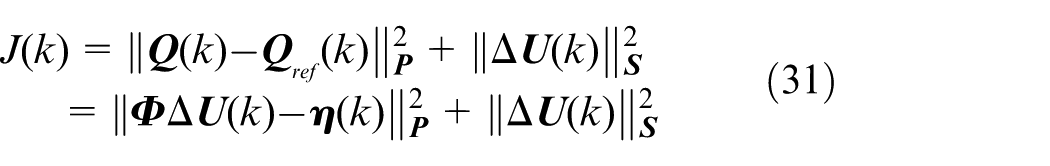
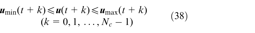
Considering the motion safety of the hydraulic quadruped robot, the motion speed and angular velocity of the robot torso should be within a certain range, that is, the motion speed and angular velocity of the hydraulic quadruped robot should meet the following constraints
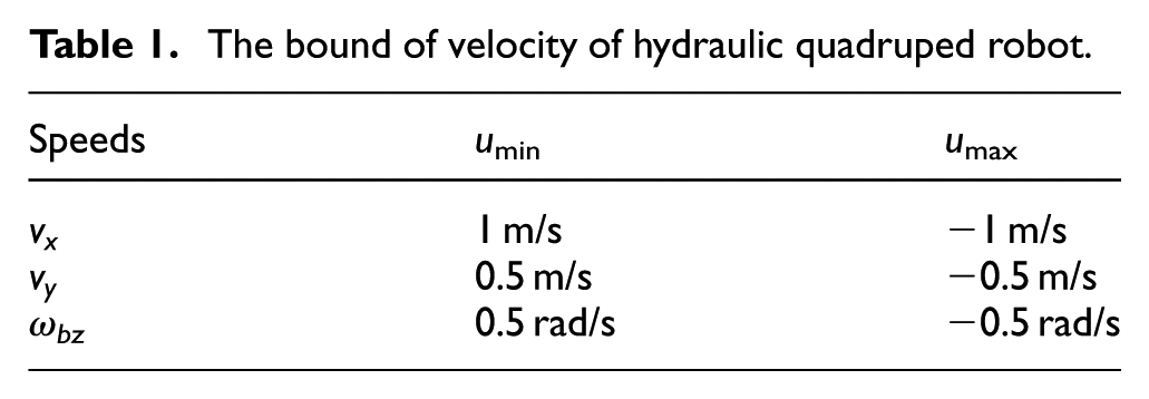
In which, v x min and v x max are the minimum and maximum values of the forward velocity of the hydraulic quadruped robot, respectively. v y min and v y max are the minimum and maximum values of the lateral velocity of the hydraulic quadruped robot, respectively. ωbzmin and ωbzmax are the minimum and maximum values of the yaw angular velocity of the torso of the hydraulic quadruped robot, respectively.
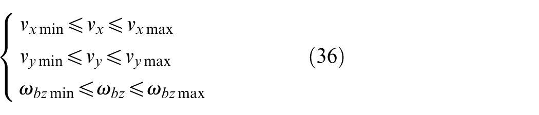
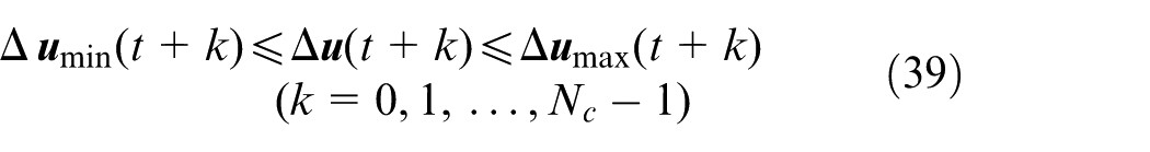
Combining the motion stability of the hydraulic robot, the acceleration and angular acceleration of the robot torso should be within a certain range, that is, the acceleration a vx , a vxy , and angular acceleration a ω bz of the hydraulic quadruped robot should meet the following constraints
In which, a vx min and a vx max are the minimum and maximum values of the forward acceleration of the hydraulic quadruped robot, respectively. a vy min and a vy max are the minimum and maximum values of the lateral acceleration of the hydraulic quadruped robot, respectively. a ω bzmin and a ω bzmax are the minimum and maximum values of the yaw angular acceleration of the torso of the hydraulic quadruped robot, respectively.
In each control cycle of the hydraulic quadruped robot, the control quantity constraint can be expressed as
Where,
The acceleration incremental constraint of the hydraulic quadruped robot can be transformed into velocity incremental constraint and angular velocity incremental constraint, hence the control incremental constraint can be expressed as
Where, Δ
Optimal control based on constraint priority
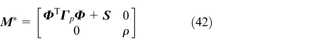
When considering the multi-constraints such as the velocity and angular velocity of the robot at the same time, the optimal control problem may have no solution. The slack variable ε is introduced to ensure the existence of optimal control solutions under multiple constraints. The trajectory tracking problem under multiple constraint conditions of quadruped robot can be represented as
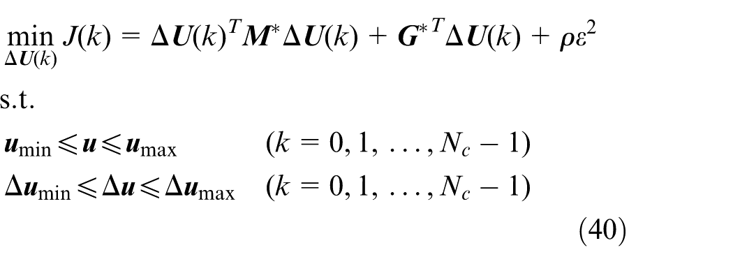
Where ρ is the weight coefficients, M * and G * are matrices related to the input model of the control system.
The objective function for the quadruped robot system in the predicting time domain as follows
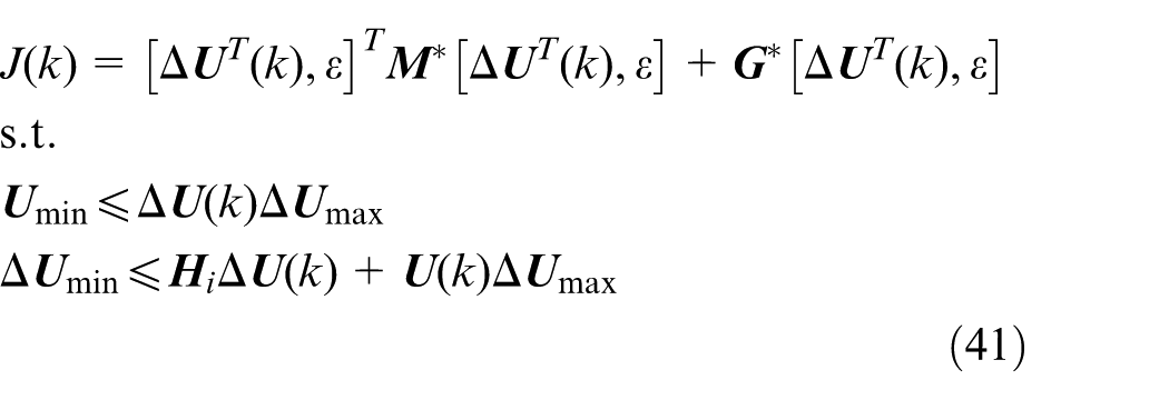
The expressions for

Where,
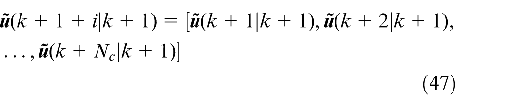
The corresponding control increment of the robot in the control time domain can be obtained according to the objective function. The input control increment of the system is the first control increment. And the control process is repeated until the trajectory tracking control of the hydraulic robot is completed.

Stability analysis
The stability of the system is proved using the Lyapunov stability theorem. Combining equation (18) and equation (40), the Lyapunov function is constructed as follows:
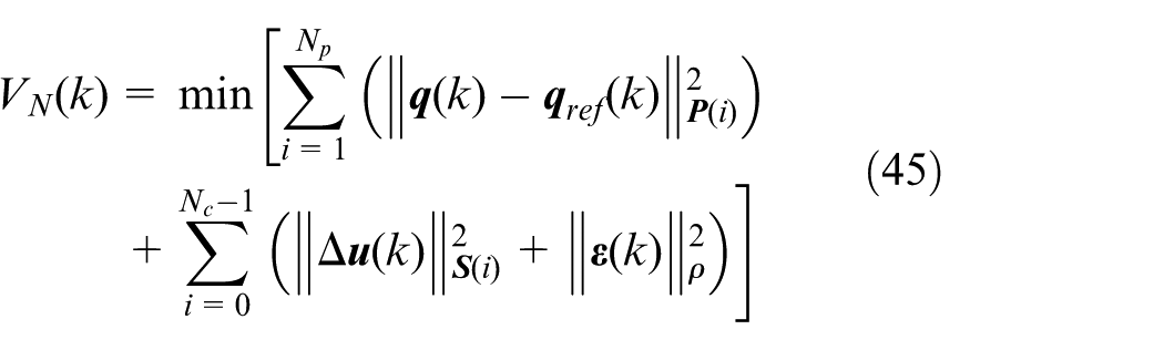
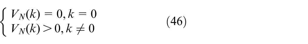
The function (45) satisfies the following conditions
From equation (19) and equation (21)

In which,
From equation (45) to equation (48)
Based on the above analysis, it can be obtained that
Combining equation (45), equation (50), and equation (51), equation (52) can be transformed into
In which,
Due to V N (k+1) is the optimal solution of the function, it can be obtained that

From equation (53),

According to equation (53),

From the above analysis, it can be concluded that the system is stable.
Design of trajectory tracking controller
Parameters of trajectory tracking
The trajectory of the foot in the corresponding leg transition coordinate system is
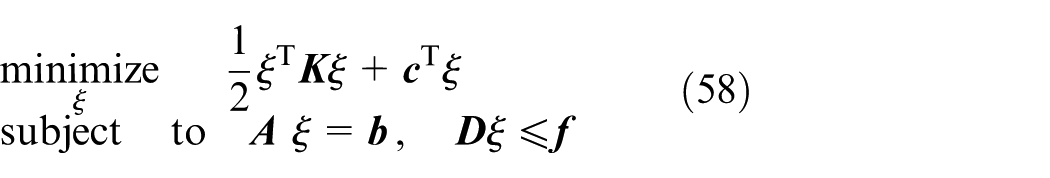
In which, ξ is the vector composed of optimize variables, K and c are matrices of appropriate dimension. when
The foot trajectory of swinging leg could be represented as
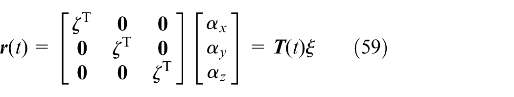
where ζ T is the basic form of trajectory, α* is the coefficient of the trajectory. The trajectory of the robot along the x, y, and z motion directions is optimized to ensure that the coefficient is included in the vector
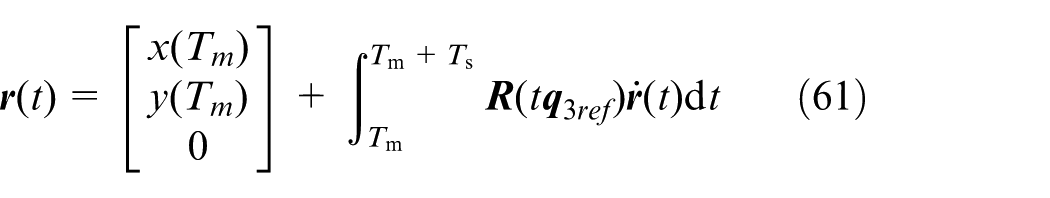
The velocity of the supporting end in the x-direction of corresponding leg transition coordinate system is a polynomial, and the velocity in the other directions is zero, the velocity vector of the foot is
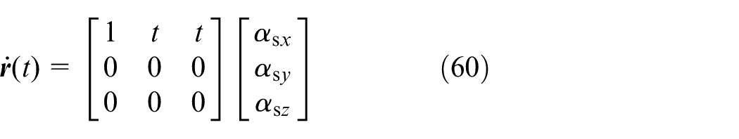
Based on the initial position of the robot support phase, the motion position vector of the foot of the robot support phase could be obtained
Where,

Where, the coefficient of the optimization variable is

Otherwise, the speed and acceleration of the supporting foot are


Target of trajectory tracking
The optimization objectives for robot trajectory tracking are as follows
Minimize of the acceleration
The smooth motion of the robot could be ensured by the minimization of acceleration. The objective function of the acceleration for supporting foot during movement time is
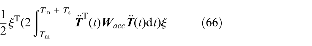
If
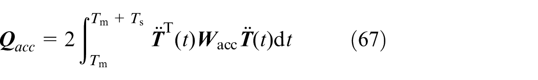
In which,
The linear term of the acceleration quadratic programing problem for quadruped robot foot is zero.

Similarly, the objective function of the acceleration of the swing foot could be obtained.
Minimize of tracking errors of position, velocity and acceleration
The actual motion trajectory of a quadruped robot deviates significantly from the expected motion trajectory, which can result in the robot being unable to complete the expected task.
To ensure the stable motion of the quadruped robot, the optimization variable for the position error of the robot’s foot end in the control time domain N p is
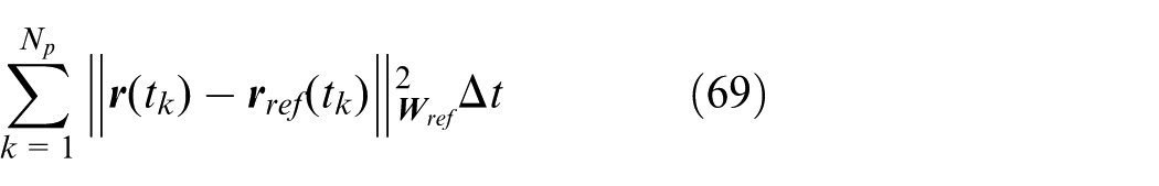
In which,
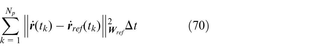
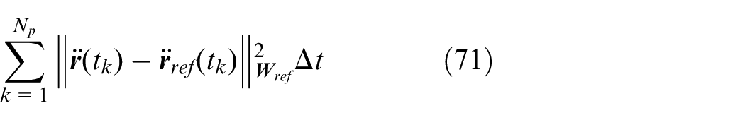
The optimization variables for the velocity error and acceleration of the robot are
Minimize of the expected speed of the supporting phase
The robot should not slip during movement, and the foot speed should track the expected speed. The objective function for minimizing the velocity of the foot is
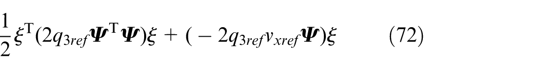
Combining with the standard form of secondary planning, it can be concluded that

Where
Minimization of tracking error of the leg height
When the robot is in the swing phase, in order to ensure that the robot’s leg lift height tracks the desired height, the objective function for minimizing the leg lift height at the foot end is
In which,


Where,
Constraints for trajectory tracking
To achieve trajectory tracking control of the foot end, the constraint conditions are as follows
Initial state of the supporting phase
Quadruped robots should effectively cope with their own disturbances and external disturbances. The constraints of initial state for the support phase of each motion cycle of the robot as follows

In the formula, x in and y in represent the actual positions of the foot, respectively.
Continuity of the trajectory
The position and speed of the foot of the quadruped robot should be continuous. At the end of the swing phase and the beginning of the support phase, the position and velocity constraints of the foot are
Trajectory tracking controller
The purpose of trajectory tracking control for hydraulic robots is to achieve speedy and stable motion along the desired trajectory. The principle of trajectory tracking control is shown in Figure 2. The motion parameters of the robot are given, and the position and attitude information of the actuators is obtained through the tracking model. Based on the error model of the system, the joint control quantities are calculated using the trajectory tracking controller, and the quadruped robot moved along the desired trajectory.
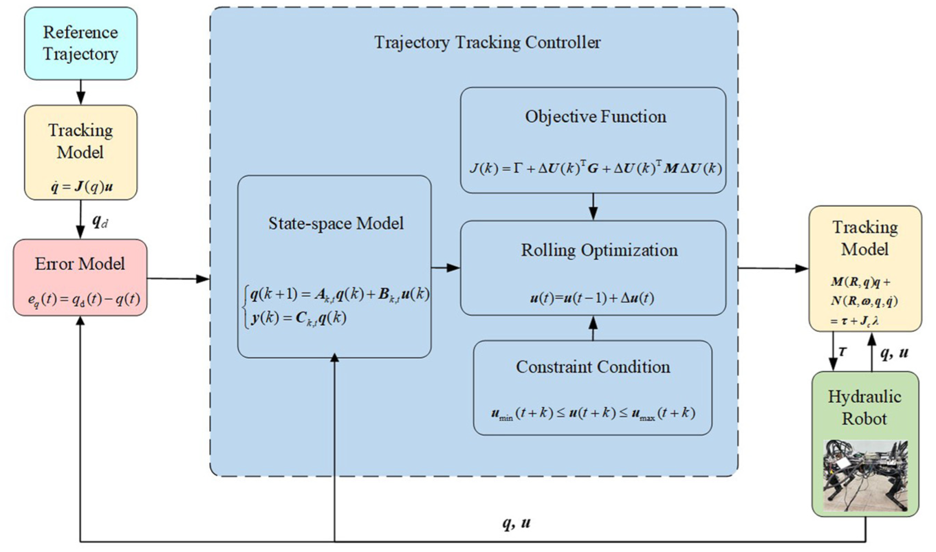
The trajectory tracking controller of quadruped robot.
Simulation
To verify the effectiveness of the trajectory tracking algorithm, by establishing the simulation model, the hydraulic quadruped robot underwent the trajectory tracking control experiments in trotting gait, and pacing gait, respectively. And the comparative analysis of the control effects between not using trajectory tracking control method and using the proposed trajectory tracking control method were completed.
Trotting gait simulation experiment
The lifting height of the foot is 70 mm, the step length is 260 mm, the running cycle is 0.8 s, and the running speed of the robot is 0.325 m/s. The process of the hydraulic quadruped robot in trotting gait is shown in Figure 3. The horizontal direction displacement curve of the torse of the hydraulic robot in trotting gait is shown in Figure 4, and the vertical displacement curve is shown in Figure 5. The figure includes three kinds of displacement data for the hydraulic robot, the target displacement, the original displacement without trajectory tracking control method, and the optimal displacement with trajectory tracking control method, respectively.
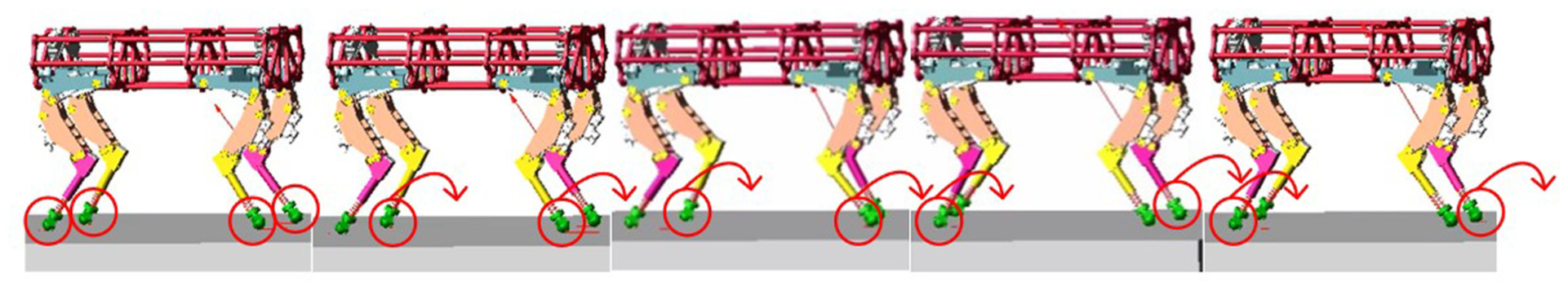
The simulation process of the hydraulic quadruped robot in trotting gait.
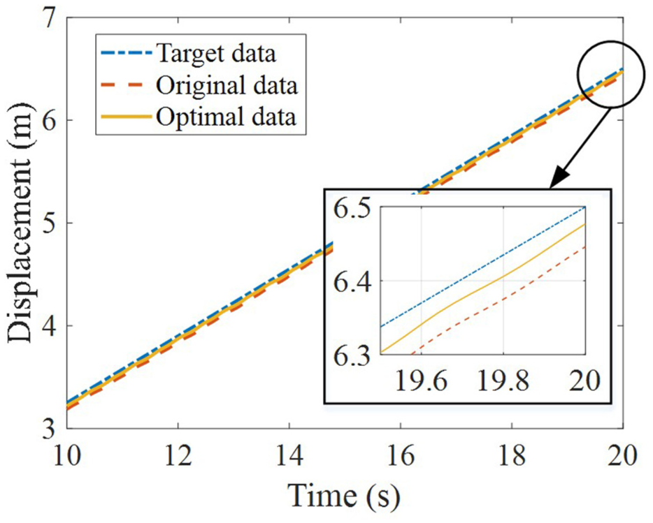
The horizontal direction displacement of the hydraulic quadruped robot torso in trotting gait.
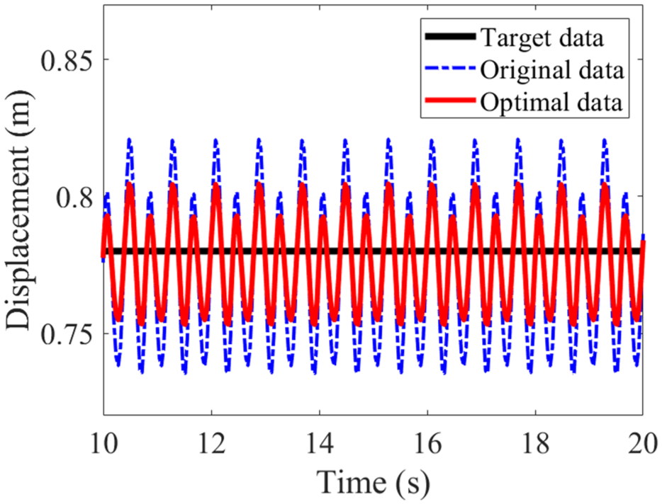
The vertical direction displacement of the hydraulic quadruped robot torso in trotting gait.
The simulation experiment results in Figures 4 and 5 could thus be obtained. As shown in Figure 4, the target displacement of the hydraulic robot in the forward direction within 20 s is 6.5 m. The original displacement without trajectory tracking control method of the robot is 6.446 m, and the trajectory tracking error is 0.83%. The optimal displacement with the proposed trajectory tracking control method of the robot is 6.477 m, and the trajectory tracking error is 0.35%. The trajectory tracking error with the proposed method of the hydraulic robot in the forward direction is significantly reduced.
According to Figure 5, the target displacement in the vertical direction is 0.78 m. The original displacement variation in the vertical direction without trajectory tracking control method is 0.735–0.821 m, and the variation range of displacement is 87 mm. The optimal displacement variation with trajectory tracking control method is 0.753–0.805 m, and the variation range of displacement is only 52 mm. The vertical displacement variation of the hydraulic robot is reduced, and the trajectory tracking error is optimized. The motion trajectory of hydraulic robot can better track the expected trajectory by the proposed method. The variation range of the center of mass of the hydraulic robot torso in the vertical direction is smaller, and the stability of the robot torso is improved.
Pacing gait simulation experiment
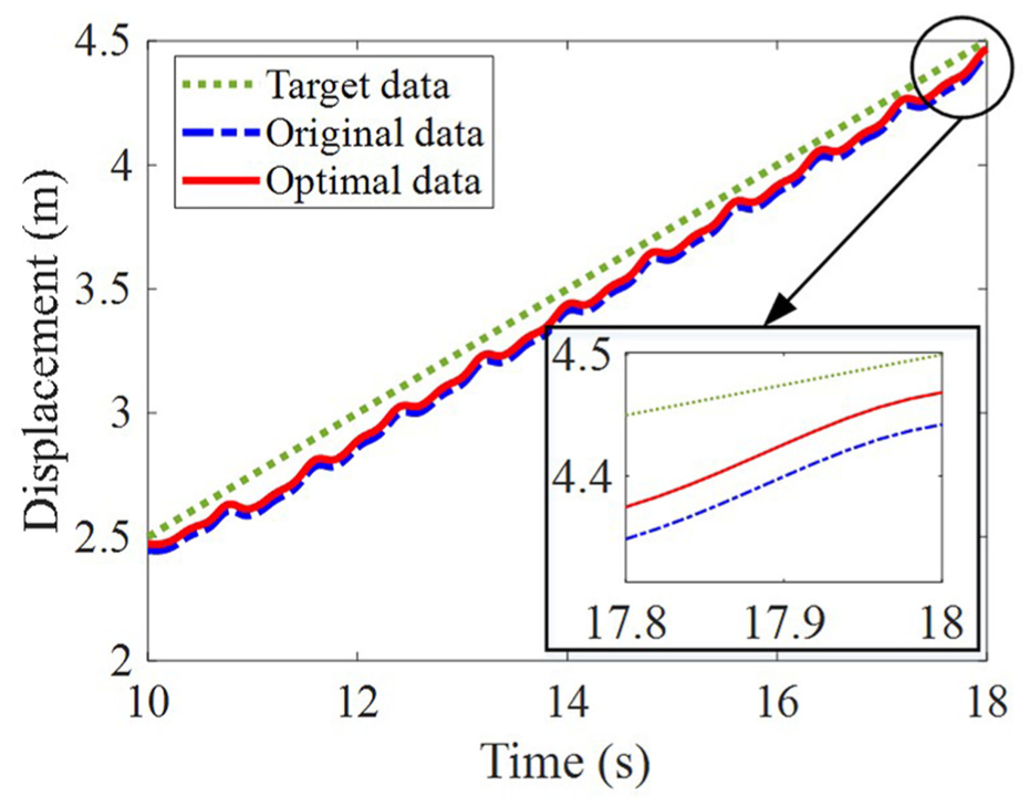
The lifting height of the foot is 70 mm, the step length is 260 mm, the running cycle is 0.8 s, and the running speed of the robot is 0.325 m/s. The process of the hydraulic quadruped robot in pacing gait is shown in Figure 6. The horizontal direction displacement curve of the torse of the hydraulic robot in pacing gait is shown in Figure 7, and the vertical displacement curve is shown in Figure 8.
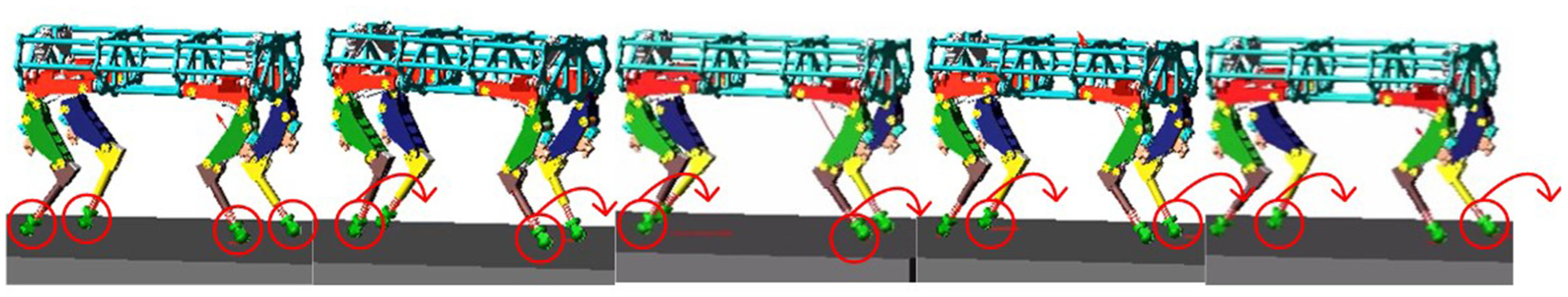
The simulation process of the hydraulic quadruped robot in pacing gait.
The horizontal direction displacement of the hydraulic quadruped robot torso in pacing gait.
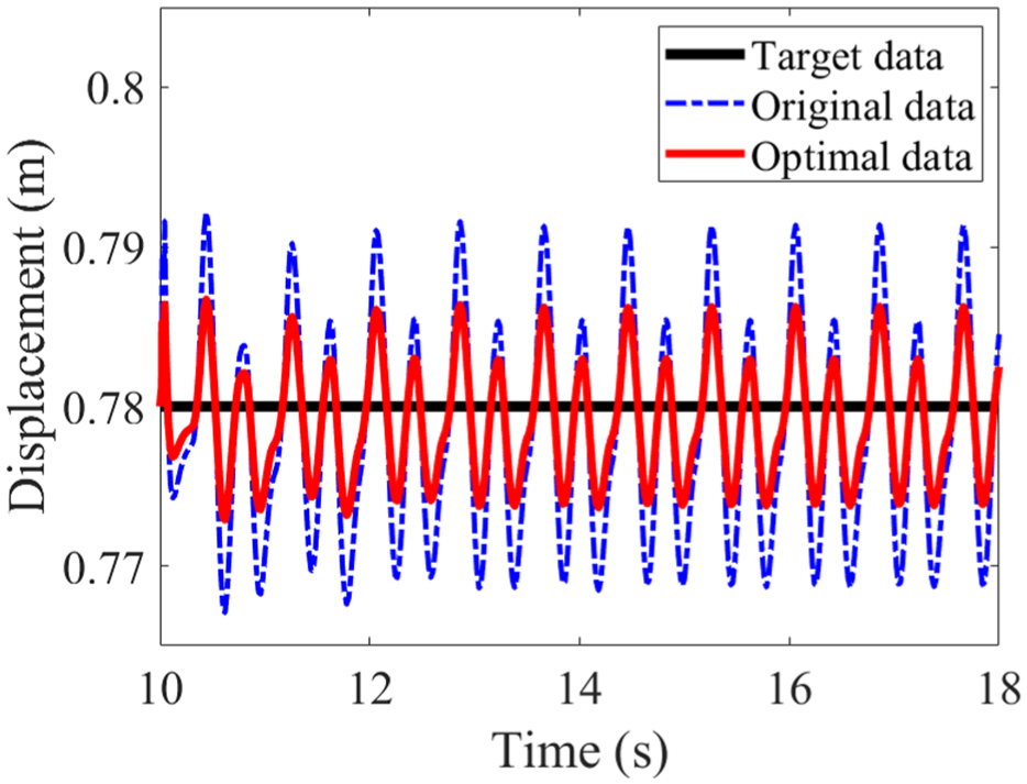
The vertical direction displacement of the hydraulic quadruped robot torso in pacing gait.
As shown in Figure 7, the target displacement of the hydraulic robot in the forward direction within 18 s is 4.5 m. The original displacement without trajectory tracking control method is 4.442 m, and the trajectory tracking error is 1.29%. The optimal displacement with the proposed trajectory tracking control method of the robot is 4.469 m, and the trajectory tracking error is 0.68%. The trajectory tracking error with the proposed method of the hydraulic robot in the forward direction in pacing gait is optimized.
As shown in Figure 8, the target displacement in the vertical direction is 0.78 m. The original displacement in the vertical direction in pacing gait without trajectory tracking control method is 0.767–0.792 m, and the variation range of displacement is 25 mm. The optimal displacement variation with trajectory tracking control method is 0.773–0.787 m, and the variation range of displacement is just 14 mm. The vertical displacement variation of the hydraulic robot in pacing gait is reduced, and the trajectory tracking error is optimized.
Based on the above simulation experiment results, it can be concluded that the error between the actual motion trajectory and the expected trajectory of the hydraulic quadruped robot by the proposed method is very small. The motion of hydraulic robots is stable. The effectiveness of the proposed trajectory tracking control algorithm based on model prediction is demonstrated.
Experiments
Experimental parameters
The trajectory tracking error of the quadruped robot during motion is analyzed. The lengths of the hip link, thigh link and shank link of the robot are 60, 340, and 370 mm, respectively. Experimental parameters are set based on the structural parameters and workspace of the hydraulic quadruped robot.
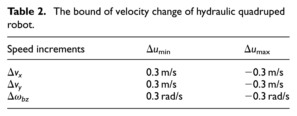
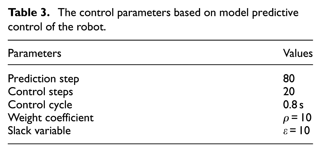
In order to verify the adaptability of the control strategy, a relatively large range of constraint parameters is set. The constraints of the robot system are shown in Tables 1 and 2. The control parameters for trajectory tracking are shown in Table 3.
The bound of velocity of hydraulic quadruped robot.
The bound of velocity change of hydraulic quadruped robot.
The control parameters based on model predictive control of the robot.
To verify the effectiveness and robustness of the trajectory tracking strategy for the hydraulic actuated quadruped robot, the experiments under different speeds of the quadruped robot are conducted.
Experimental analysis under 0.225 m/s
The trajectory tracking control experiments in trotting gait are conducted by hydraulic quadruped robot experimental platform, including experiments without trajectory tracking control method and experiments with trajectory tracking control method. The process of the hydraulic quadruped robot in trotting gait is shown in Figure 9.
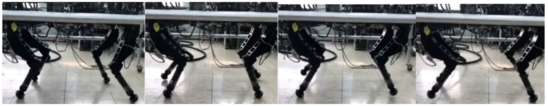
The process of the hydraulic quadruped robot in trotting gait.
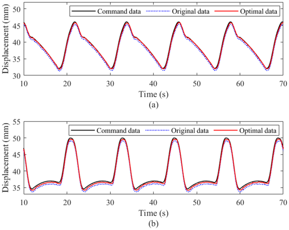
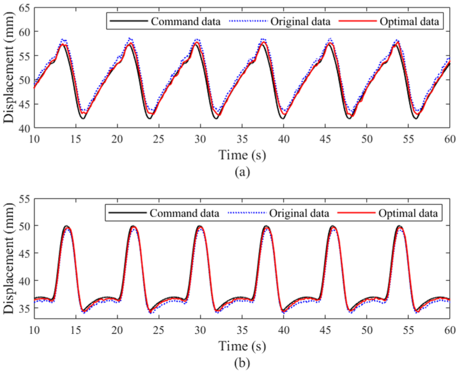
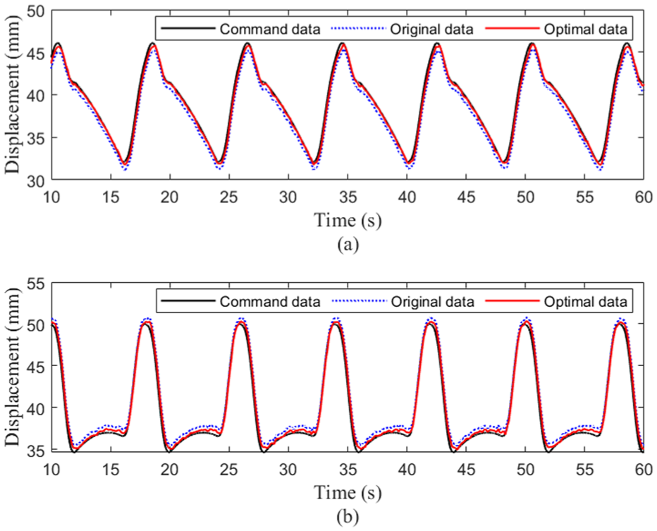
The displacement data of the leg actuators for the right front leg, right behind leg, left behind leg, and left front leg of the hydraulic robot are shown in Figures 10 to 13, respectively. Figure (a) shows the displacement data of the hip joint actuator of the hydraulic robot, and Figure (b) shows the displacement data of the knee joint actuator. There are three sets of data in each figure, which are the command displacement data of the actuator, the original data of the joint actuator without trajectory tracking control method, and the optimal data of the joint actuator using the trajectory tracking control method proposed in this paper.
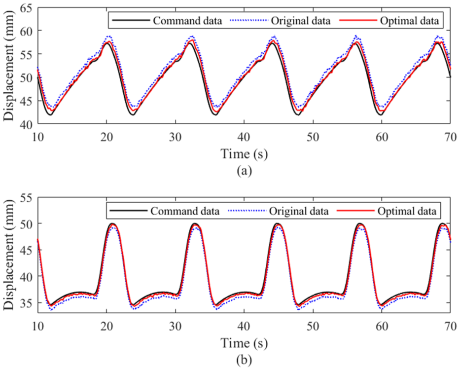
Displacement tracking experiment of right front leg of the hydraulic robot under 0.225 m/s: (a) hip joint and (b) knee joint.
Displacement tracking experiment of right hind leg of the hydraulic robot under 0.225 m/s: (a) hip joint and (b) knee joint.
Displacement tracking experiment of left hind leg of the hydraulic robot under 0.225 m/s: (a) hip joint and (b) knee joint.
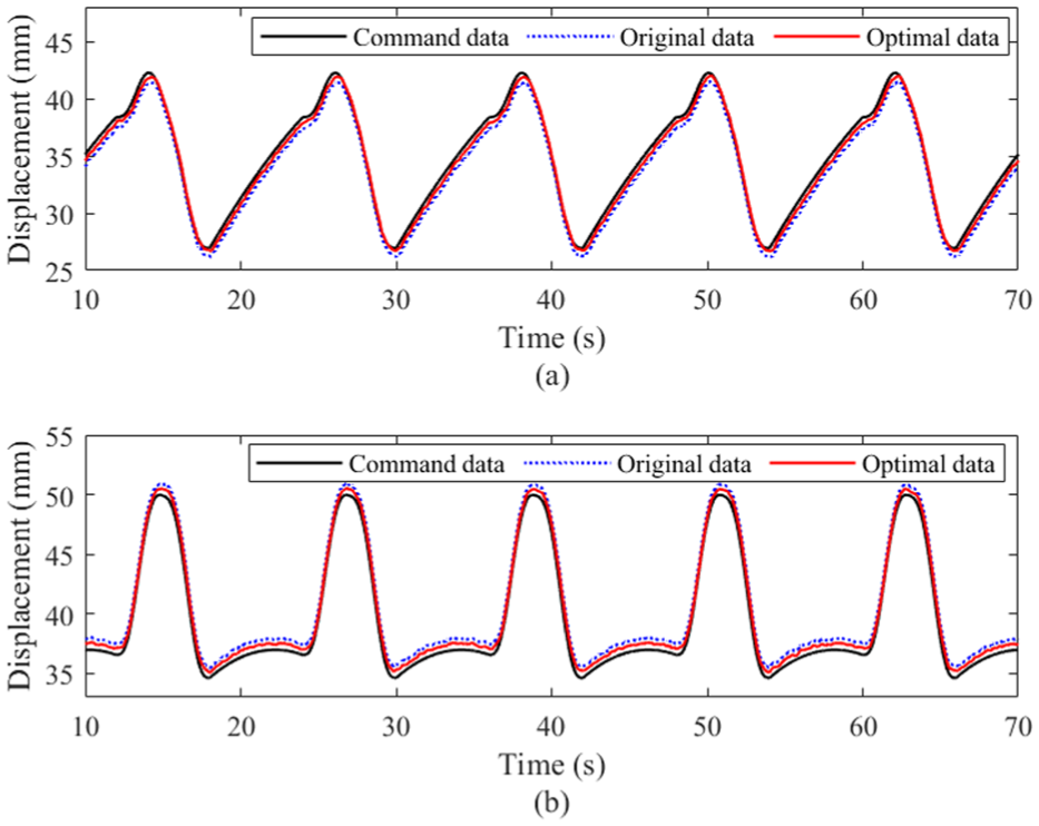
Displacement tracking experiment of left front leg of the hydraulic robot under 0.225 m/s: (a) hip joint and (b) knee joint.
The absolute values of the original trajectory maximum tracking errors for the hip joint actuators are 1.62, 1.032, 0.809, and 0.808 mm, respectively. And the absolute values of the optimal trajectory maximum tracking errors are 0.719, 0.432, 0.31, and 0.309 mm, respectively. The absolute values of the original trajectory maximum tracking errors for the knee joint actuators are 0.978, 0.797, 1.037, and 1.796 mm, respectively. And the absolute values of the optimal trajectory maximum tracking errors by the proposed method are 0.377, 0.346, 0.536, and 0.396 mm, respectively. The trajectory tracking error of the hip joint actuator of the hydraulic robot is reduced by the proposed trajectory tracking method.
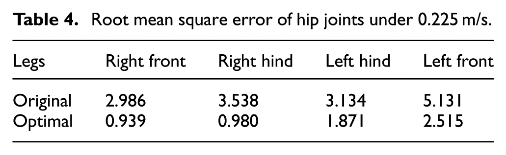
Comparing the original data and the optimal data with the command data, the root mean square tracking errors of each joint actuator of the hydraulic quadruped robot are obtained. Table 4 shows the mean square error of hip joint actuators, and Table 5 shows the mean square error of knee joint actuators.
Root mean square error of hip joints under 0.225 m/s.
Root mean square error of knee joints under 0.225 m/s.
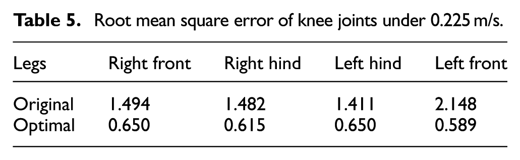
From the tables, it can be seen that using the proposed model predictive control method, the hip joint actuator errors of the right front, right hind, left hind, and left front are reduced by 68.55%, 72.3%, 40.28%, and 50.99%, respectively. And the knee joint actuator errors of the right front, right hind, left hind, and left front are reduced by 56.48%, 58.5%, 53.93%, and 72.58%, respectively.
Figure 14 gives the values of attitude angle of the hydraulic quadruped robot. As shown in Figure 14, by using the proposed trajectory tracking control method, the range of rolling angle for the hydraulic robot is −0.066 to 0.066 rad, and the range of pitching angle is −0.073 to 0.044 rad.
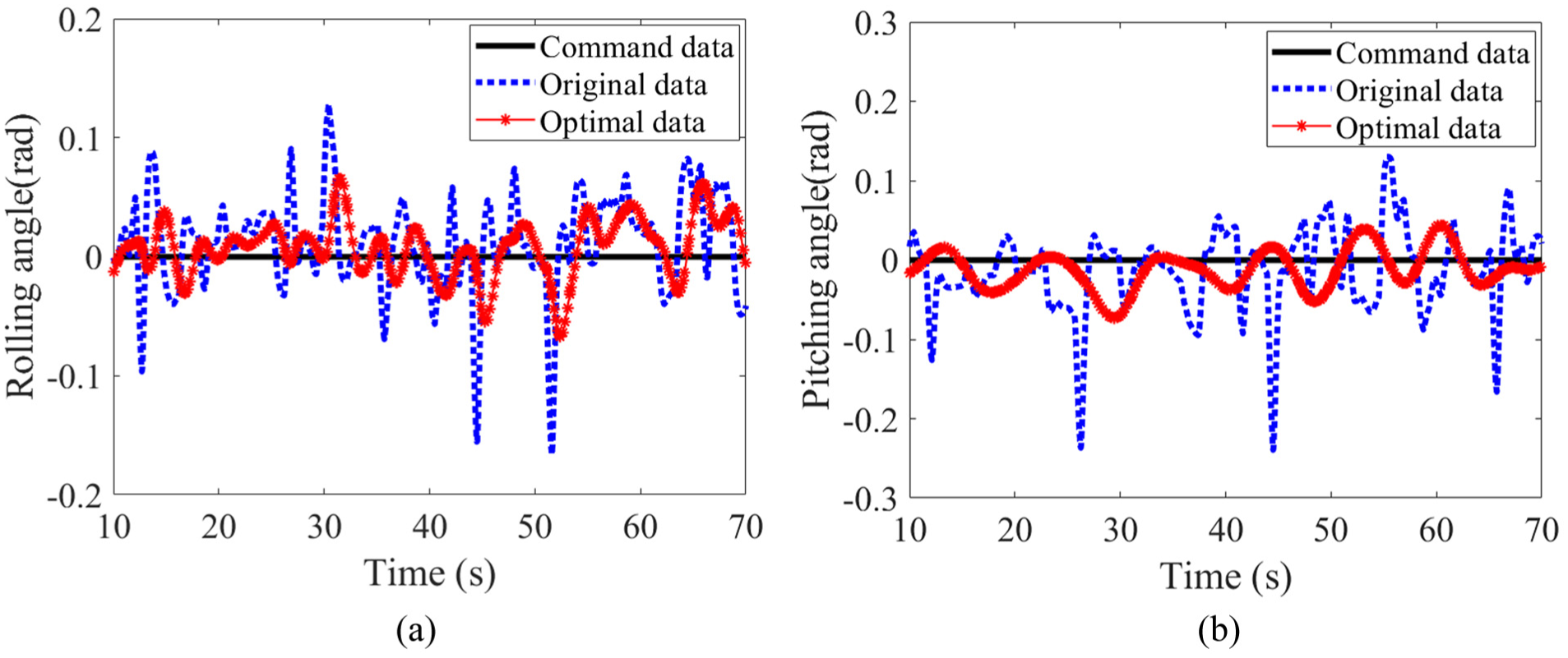
Curves of attitude angle of the hydraulic robot under 0.225m/s: (a) rolling angle and (b) pitching angle.
Experimental analysis under 0.315 m/s
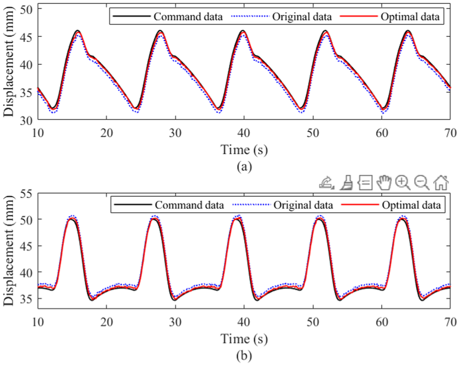
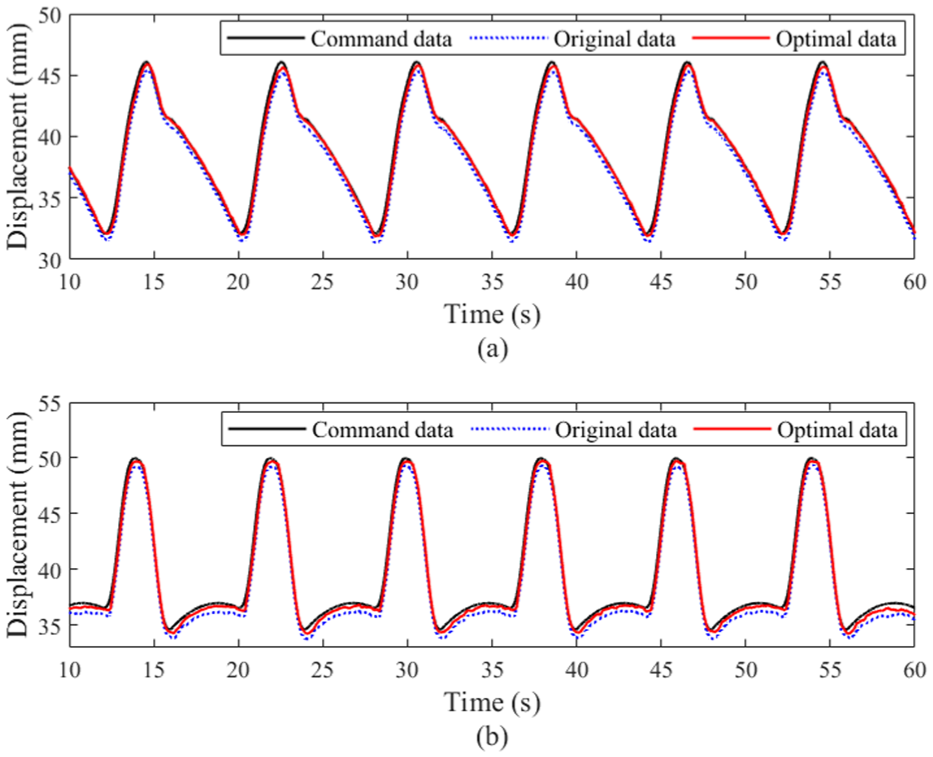
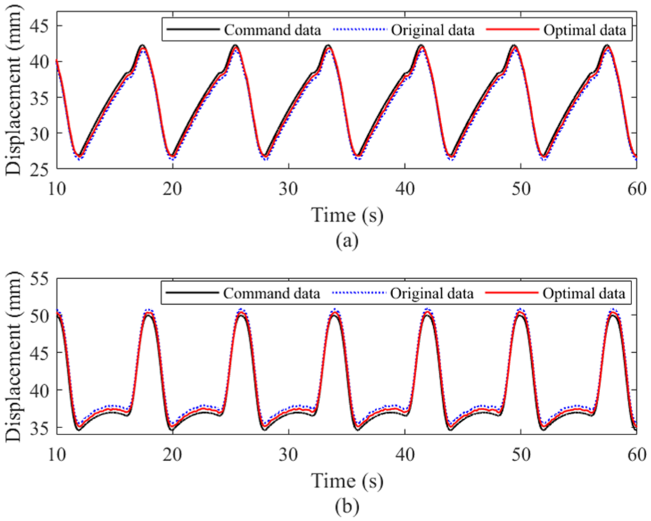
The displacement data of the leg actuators the hydraulic robot under 0.315 m/s are shown in Figures 15 to 18, respectively. From the figures, it can be seen that the trajectory tracking of the joint actuators of the hydraulic robot are closer to the expected trajectory by the proposed trajectory tracking method.
Displacement tracking experiment of right front leg of the hydraulic robot under 0.315 m/s: (a) hip joint and (b) knee joint.
Displacement tracking experiment of right hind leg of the hydraulic robot under 0.315 m/s: (a) hip joint and (b) knee joint.
Displacement tracking experiment of left hind leg of the hydraulic robot under 0.315 m/s: (a) hip joint and (b) knee joint.
Displacement tracking experiment of left front leg of the hydraulic robot under 0.315 m/s: (a) hip joint and (b) knee joint.
The absolute values of the original trajectory maximum tracking errors for the hip joint actuators are 1.54, 1.23, 0.84, and 0.956 mm respectively. And the absolute values of the optimal trajectory maximum tracking errors are 0.692, 0.465, 0.323, and 0.454 mm, respectively. The absolute values of the original trajectory maximum tracking errors for the knee joint actuators are 0.945, 0.827, 1.206, and 1.656 mm, respectively. And the absolute values of the optimal trajectory maximum tracking errors by the proposed method are 0.415, 0.387, 0.517, and 0.618 mm, respectively.
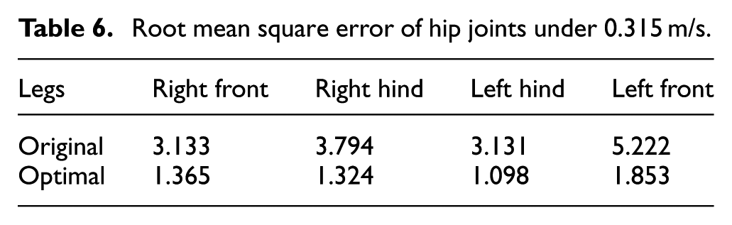
Comparing the original data and the optimal data with the command data, the root mean square tracking errors of each joint actuator of the hydraulic quadruped robot are obtained. Table 6 shows the mean square error of hip joint actuators, and Table 7 shows the mean square error of knee joint actuators.
Root mean square error of hip joints under 0.315 m/s.
Root mean square error of knee joints under 0.315 m/s.
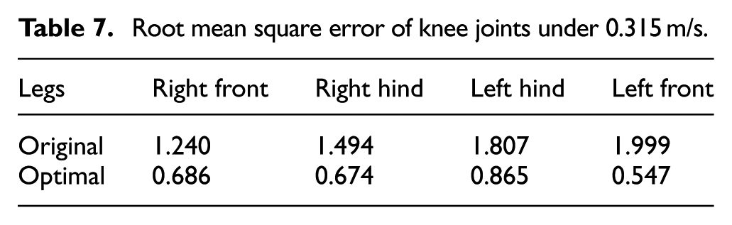
From the tables, it can be seen that using the proposed model predictive control method, the hip joint actuator errors of the right front, right hind, left hind, and left front are reduced by 56.45%, 65.11%, 64.95%, 64.52%, respectively. And the knee joint actuator errors of the right front, right hind, left hind, and left front are reduced by 44.63%, 54.87%, 52.13%, 72.64%, respectively.
Figure 19 gives the values of attitude angle of the hydraulic quadruped robot. As shown in Figure 19, by using the proposed trajectory tracking control method, the range of rolling angle for the hydraulic robot is −0.023 to 0.086 rad, and the range of pitching angle is −0.031 to 0.1 rad. From the comparison between the original data and optimal data in the figures, it can be seen that the stability of the robot can be improved by the proposed trajectory tracking control method.
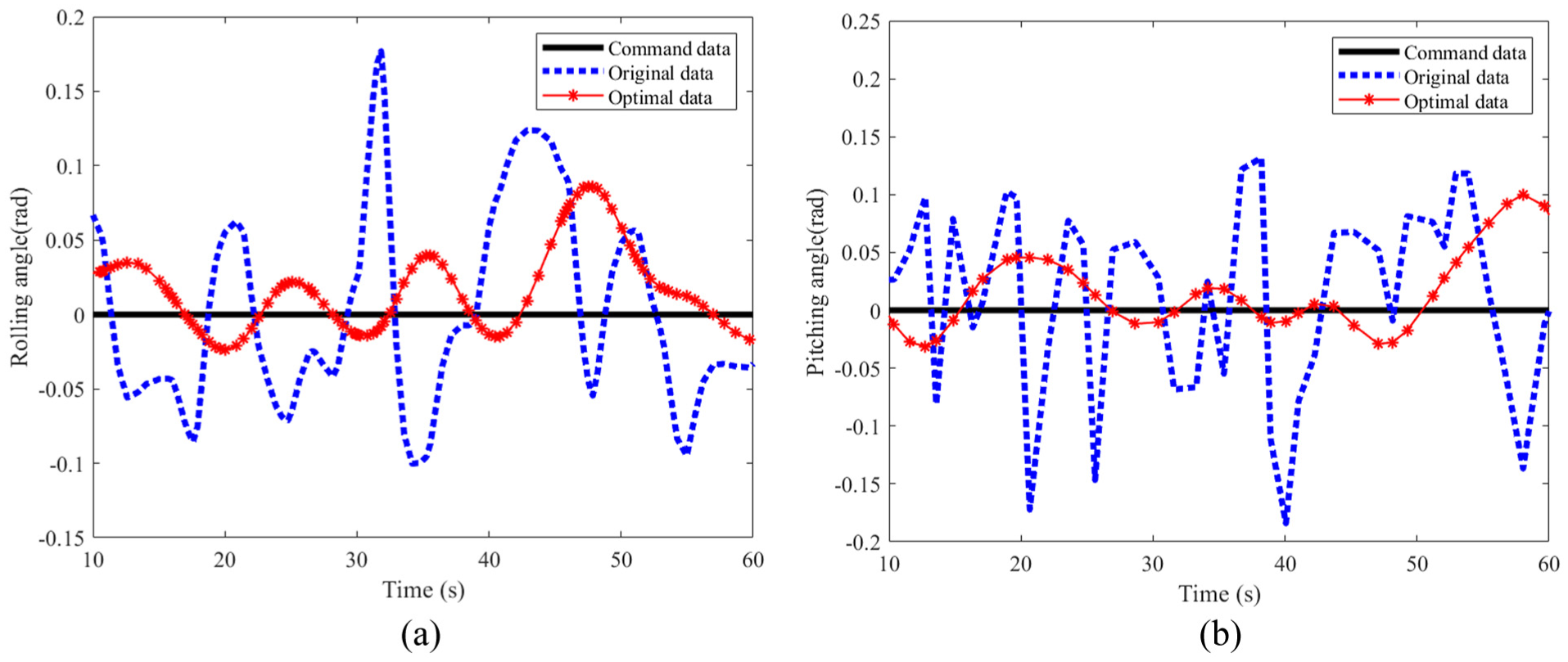
Curves of attitude angle of the hydraulic robot under 0.315m/s: (a) rolling angle and (b) pitching angle.
From the above experimental results, it can be concluded that the hydraulic robot can track the command trajectory better by the proposed trajectory tracking control method. And the error between the optimal displacement and the expected displacement of each actuator is smaller. The trajectory tracking accuracy and the stability of hydraulic robot is improved by the proposed method. And the effectiveness of the proposed control method is proved.
Conclusions
In order to meet the high precision trajectory tracking performance requirements of hydraulic robot. Aiming at the multi coupling characteristics of hydraulic robot, a decomposed trajectory tracking control strategy with trajectory constraints for hydraulic robot is proposed. The effectiveness of proposed strategy was verified through simulation and prototype experiments. This paper mainly completes the following four aspects:
(1) The tracking model of the hydraulic robot was derived. Considering the inequality constraints during the motion of the quadruped robot, the trajectory tracking control problem of the robot was transformed into a quadratic programing problem. The trajectory tracking controller with trajectory constraints was designed, and the accuracy of the robot model in the control algorithm was improved.
(2) Combining the minimization goals of robot motion speed and acceleration error, stability and continuity constraints for robot motion were designed, the impact during hydraulic robot motion was reduced, and the service life of the robot was increased, as well as the stability of robot motion was enhanced.
(3) The impact of classical control strategies and the proposed control strategy on robot performance was compared through simulation. The motion trajectory error of the robot is relatively small by the proposed trajectory tracking control strategy, and the effectiveness of the control strategy in simulation was proved.
(4) The prototype experiments on trajectory tracking control of hydraulic robots were conducted. And the effectiveness and robustness of the proposed control algorithm in practical quadruped robot system was verified by the experimental results.
The above results provide a basis for further research on motion control algorithms and hydraulic quadruped robot control. Future work will involve the detailed design of stability strategies for robot, as well as conducting application studies on actual hydraulic robots.
Footnotes
Ethical considerations
The authors declare that all participation is voluntary and all authors approve the submission of the paper. This article does not contain any studies with human or animal participants. The authors confirm their contribution to the paper as follows: Dongyi Ren performed the conceptualization methodology formal analysis investigation writing - original draft and Funding acquisition. Guitao Sun performed the supervision and writing - review and editing. All authors reviewed the results and approved the final version of the manuscript.
Funding
The authors disclosed receipt of the following financial support for the research, authorship, and/or publication of this article: This work was supported by the Foundation of Doctoral Scientific Research of Shandong Management University (SDMUD202125).
Declaration of conflicting interests
The authors declared no potential conflicts of interest with respect to the research, authorship, and/or publication of this article.
Data availability statement
The data that support the findings of this study are available from the corresponding author upon reasonable request.