
Abstract
In a high-power microwave device, the intense electron beam causes a high-heat-flux on the collector’s inner surface which results in an instant temperature increase which eventually causes the output power to drop. The vapor chamber is one of the passive cooling devices effective for high-heat-flux heat dissipation. To study the heat dissipation capacity and the surface temperature control effect of the vapor chamber, a numerical heat transfer model of the vapor chamber is proposed based on the effective thermal conductivity method. The accuracy of the steady-state heat transfer analysis and the applicability of the transient simulation are verified by comparing with experimental data, and the heat transfer are calculated under the condition of periodic pulsed heat sources. Lastly, the transient performance of a vapor chamber relative to a copper heat spreader of the same external dimensions is investigated as a function of the wick effective thermal conductivity, pulsed heat flux, and pulse duration. The transient behavior of the vapor chambers are examined to find a performance threshold to determine if the performance is superior to that of a copper heat spreader. The present work provides a basis to understand the advantages and limitations of metal heat spreader in pulse mode operation of vapor chamber and plays a vital role in the design of improving transient performance.
Keywords
Introduction
The collector in a high-power microwave device is a component that collects the high-current electron beam in the backward-wave oscillator. Intense electron beam causes a high-heat-flux and instantaneous high temperature on the inner surface and this will cause thermal desorption of adsorbed gas on the surface so that the output power drops in a polluted vacuum environment.1–4 Benford and Swegle5,6 has pointed out in his books that any measures to reduce thermal load are critical in the high-power microwave field, especially in burst-mode operation. in which the cooling system required to handle dissipated power must be considered as a fundamental element in a repetitive system.
Interest in extending the use of vapor chambers to high heat flux electronics cooling has grown, because of their low thermal resistance values and uniform temperature distribution abilities. 7 Mo et al. 8 manufactured a vapor chamber and studied its heat transfer characteristics by performing a high-heat-flux heat transfer experiment. Experimental results showed that the vapor chamber can suffer from a high heat flux. To assess the effective thermal conductivity of the vapor, Prasher 9 introduced a simplified conduction-based modeling scheme. The results were compared with experimental data for vapor resistance and wall temperature distribution. Chen et al. 10 studied a numerical simulation of a heat sink embedded in a vapor chamber and calculated the effective thermal conductivity. A numerical analysis of the overall performance of a thermal module was presented. The results showed that the area of the heat source had a significant effect on the performance of the vapor chamber. To illustrate the effect of the power input and the heat transfer coefficient of the cooling fluid on the performance, Hassan and Harmand 11 studied a three-dimensional thermal and hydrodynamic numerical model using a vapor chamber for cooling electronic devices. Their results showed that, when the power input or the heat transfer coefficient of the cooling fluid increased, the maximum pressure difference between the flat heat pipe and the convection inside the wick regions increased as well. According to the current research, the numerical simulation and experimental study of vapor chambers are focused on the effect of wick structure, the working fluid, and the heat sink that affect their performance, by optimizing the vapor chamber’s design, to reduce the thermal resistance and improve the critical heat flux.12–15 In the numerical simulation, the effective thermal conductivity method is a suitable way to improve the efficiency of numerical calculation. Currently, most of the numerical simulations are steady-state heat transfer analyses, and the Garimella team16,17 at Purdue University has published some research results on transient heat transfer, but there is little research on the numerical simulation of periodic pulsed heat source.
In burst-mode operation of high-power microwave devices, high thermal conductivity materials such as graphite or copper are generally used for electronic collection and thermal diffusion. The heat fluxes of a few hundred W/cm2, about 10 mm deposition duration, millisecond pulse duration, and 10–100 Hz frequency, are formed at the interface between the collector and the outer structure. To study the heat dissipation capacity and surface temperature control effect of the vapor chamber under this condition, a numerical heat transfer model of the vapor chamber is established in this paper, based on the effective thermal conductivity method. The accuracy of the steady-state heat transfer analysis and the applicability of the transient simulation is verified by comparing analyze and simulated results with experimental datas, and the heat transfer are calculated under conditions of periodic pulsed heat sources. Finally, according to the functional relationship including these parameters wick effective thermal conductivity, pulsed heat flux, and pulse duration, thresholds are identified beyond which the vapor chamber offers improved performance relative to the copper heat spreader. The relationship between the characteristics and the transient performance thresholds is established.
Mathematical model description
Geometry, governing equations, and boundary conditions
A vapor chamber is a flat heat pipe with rectangular cross section employed for heat spreading. 7 In the present study, for simplicity reasons and to save computing time, a two-dimensional vapor chamber is discussed. The schematic diagram of the studied vapor chamber is shown in Figure 1. The flat heat pipe consists of two copper pipe walls, two copper–water wicks, and a vapor core between the two wicks.
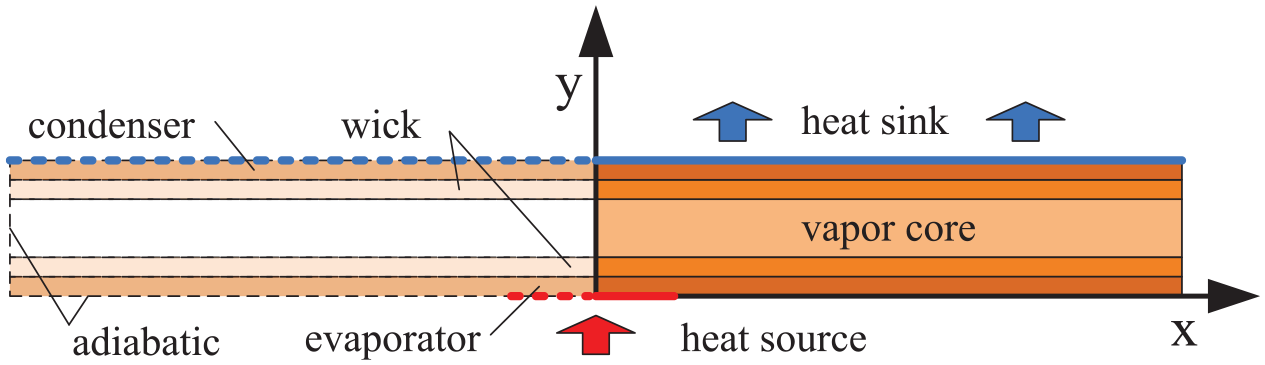
Two-dimensional numerical calculation model of a vapor chamber.
In the engineering design, the flow process convection of the working fluid in the heat pipe is usually simplified. 18 Thus, the thermal conductivity model containing the wick and the vapor core is used instead. In this way, it’s not necessary to be solve the flow equation for the heat transfer model of the heat pipe, but heat conduction equation, 19 expressed by equation (1), is required.

This is a two-dimensional heat conduction equation.
Equation (2) is the heat transfer surface equation of heat source.

Equation (3) is the convection heat dissipation equation of heat sink.

While other surfaces are adiabatic.

Effective thermal conductivity method
For a common screen wick, it is usually assumed that a distribution cylinder is filled with liquid, so effective thermal conductivity

Prasher 9 used the Clapeyron equation and the ideal gas law to derive the effective thermal conductivity of the vapor space as a function of vapor space thickness and thermodynamic properties. The vapor was considered theoretically to be incompressible and the vapor flow was laminar and fully developed. The effective thermal conductivity of the vapor core can be calculated by using equation (6).

The theoretical value calculated by equation (6) is usually higher than the actual one. If the thermal conductivity of the wick is different from that of the vapor core, large simulation errors will occur. The change of the phase of the working fluid is the main heat transfer mechanism in the vapor chamber. The heat transfer is much stronger than that in the solid wall and the wick. Therefore, in the calculations of the simulation, the vapor core is regarded as the equivalent of the heat transfer interface between the solid structures, thus it is assumed that the physical non-contact surfaces of both sides of the vapor core, share a heat transfer interface. 9
For the vapor chamber which determines the heat transfer power, it is assumed that the temperature difference between the two sides of the vapor core meets the lower value of calculation precision, such as 0.001 K. The theoretical effective thermal conductivity value of the vapor core is calculated by equation (7).

If the theoretical value of the effective thermal conductivity
Model verification
To validate the numerical model, the results of the numerical model are compared with the results of the experimental work. The dimensions of the model, the properties of the material, and the parameters of the cooling system are shown in Table 1.
Model structure size and material thermal properties.

The parameters of the model structure, such as dimensions and porosity, were the same as those mentioned in the literature. 21 The wick is formed as a screen core with a porosity of 0.7. The equivalent density and specific heat capacity of the wick are calculated by the parallel assumption condition of porous media. 22 The input power of the heat source is 5.34 W, the size is 10 mm, the convective heat transfer coefficient of the heat sink was 110 W/m2 K, the temperature of cooling gas was 293 K, and the heat conductivity of the vapor core was calculated by equation (6) or (7).
To verify the grid independence of the symmetric calculation model, numerical simulation software FLUENT 23 was used, the temperature results of the evaporative section were compared with those of Figure 2, and the number of meshes obtained was 4056.
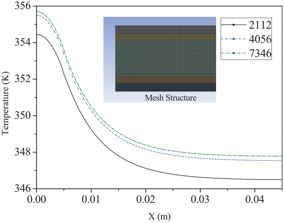
Temperature distribution of mesh independent verification.
As shown in Figure 3, the results of the temperature distribution trend of the steady-state analysis are in good agreement with the experimental ones. 21 The calculated results of the evaporator temperature were very high because the wick and the vapor core are of equivalent thermal conduction, so there are some errors in respect to the actual flow. There are some differences between the coefficient of the convection of the heat transfer in the calculation and the heat dissipation method in the experiment.
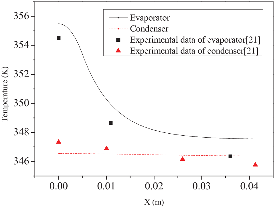
Theoretically calculated and experimental temperature of vapor chamber in 5.34 W stability power.
Results and discussion
Transient heat transfer simulation of periodic-pulsed heat source
The calculation results of the starting process of the vapor chamber are shown in Figure 4. The conditions are the same as in Section 2.3. From the start-up, the evaporator and the condensation sections are heated up simultaneously. The heating speed was fast for the first 200 s, and the temperature rise rate is relatively high in the evaporator. However, the temperature rise rate is slow after 200 s, and the temperature became stable after about 600 s. The mean temperature of both the evaporator and the condenser varies with time, which is close to the trend of the experimental results. 21 Thus, the model is suitable for the numerical simulation of the plate transient.
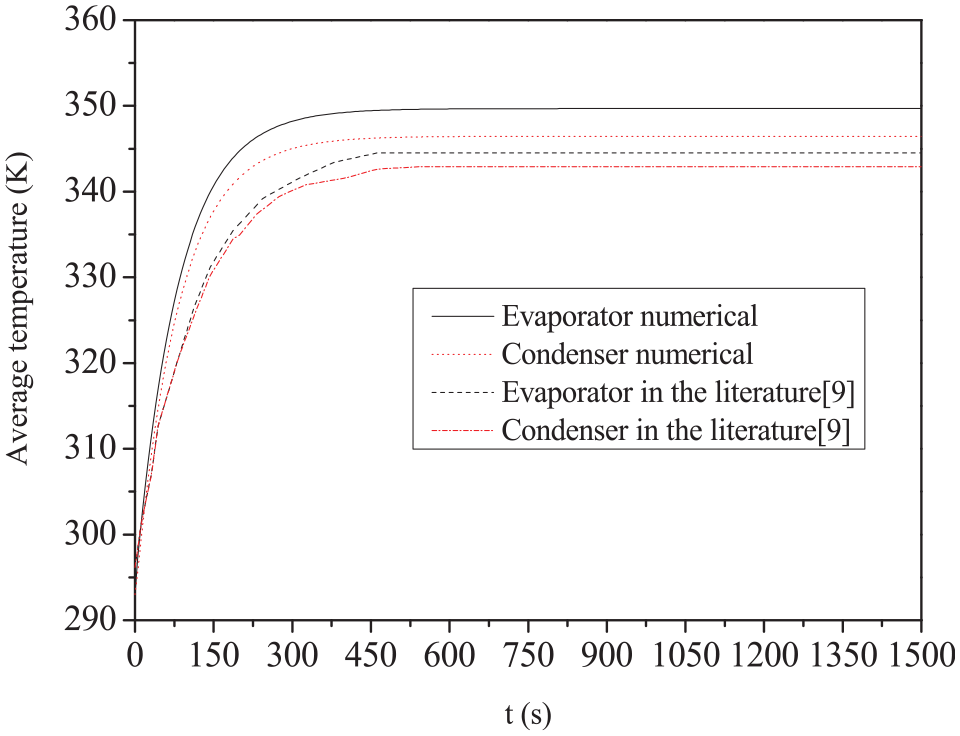
The average temperature in the start-up process on the two sides of the vapor chamber.
Similar to the steady-state start-up model, the pulsed heat flux is 300 × 104 W/m2, the pulse duration is 10 ms, and the frequency is 10 Hz, as shown in Figure 5. The convective heat transfer coefficient of the heat sink is 650 W/m2 K, and the temperature of cooling gas is 293 K.
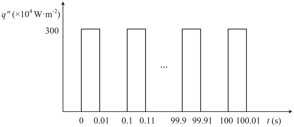
The periodic pulse heat source of burst-mode operation.
The start-up process is calculated under the condition of the periodic pulsed heat source. Figure 6 shows that the average temperature and the maximum temperature of the evaporator are pulse-shaped with the power of the heat source and increase with time. The temperature until 40 s increases rapidly, then it slows down until 90 s, basically reaching the dynamic equilibrium state, and it is believed that the vapor chamber had start-up to steady-state operation.
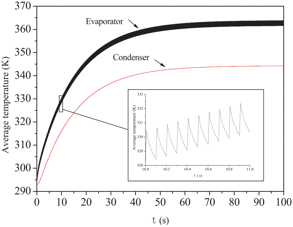
Start-up process under the periodic-pulsed heat source.
After start-up, the average temperature of the evaporator fluctuated periodically between 361.6 and 363.6 K, and the temperature of the condensation section remained at 344.2 K. As shown in Figure 7, the maximum temperature of the evaporator kept fluctuating between 390.6 and 410.5 K.

The maximum temperature during start-up process under the periodic-pulsed heat source.
The thermal performance of a vapor chamber relative to a copper spreader under theperiodic-pulsed heat source
According to the results in Section 3.1, the maximum temperature in each heat source period of the components, which appears at the end of the peak power, indicates the heat dissipation capacity and the ability to resist pulse high heat flux. This section investigates the dependence of vapor chamber performance, relative to a copper spreader of equal external dimensions, on the vapor chamber wick effective thermal conductivity. Generally, the total thermal capacity of the vapor chamber is lower than the copper spreader, due to the very low thermal capacity of the vapor core, this contrast increases with increasing input energy. But the total thermal resistance of the vapor chamber is smaller, this diffusion effect is better. The wick effective thermal conductivity is a key parameter of the total thermal conductivity and also affects the temperature at the end of the pulse. Therefore, the sensitivity of the key parameter to the operating temperature is judged and the heat dissipation performance results of the vapor chamber and the copper spreader are obtained by studying the variation of the maximum operating temperature with time.
The relative performance is presented using a function defined in equation (8).

Where θp, VC and θp, Cu correspond to the peak evaporator temperatures relative to the ambient (T − T∞) of the vapor chamber and the copper spreader, respectively. The function fitted the discrete maximum temperature to the ratio in the period into a continuous form to show the development trend with time.
The vapor chambers and a copper spreader of identical external geometry are simulated under the same heat input and convective boundary condition in Section 3.1. The relative transient thermal performance contour plot of a copper spreader relative to a vapor chamber for a range 5∼15 W/m2 K of the wick effective thermal conductivity and as a function of time are mapped in Figure 8 for some time of 100 s.

Contour plot of the metric for the thermal performance of a copper spreader relative to a vapor chamber for a range of the wick effective thermal conductivity and as a function of time.
A value of zero for MVC-Cu corresponds to equal performance for both heat spreaders; this performance threshold is shown in white on the contour scale in Figure 8. A positive value, shown in red, indicates the vapor chamber performs better while a negative value, shown in blue, indicates the copper spreader performs better. Figure 8 shows θp, VC increases faster than θp, Cu in the initial diffusion period (t < 3 s), then θp, Cu is going to be higher than θp, VC of the vapor chamber with the higher wick effective conductance. The higher value alternates between θp, VC and θp, Cu in the range of 9–12 W/m2 K within 50 s. For example, for a vapor chamber with the wick effective thermal conductivity of 11 W/m2 K, the higher thermal resistance of the wick near-evaporator region causes the relative temperature θp, VC higher than θp, Cu in the initial diffusion period (t < 3 s). While the energy through the lower thermal resistance of the vapor core region, higher effective in-plane diffusivity of the vapor chamber causes the θp, VC lower than θp, Cu at 3–9 s. At later times (t > 9 s), the higher thermal resistance of the wick near-condenser region causes θp, VC higher than θp, Cu due to its lower diffusivity. Approximately 30 s later, a steady-state condition is reaching, θp, VC is always lower than θp, Cu owing to a smaller total thermal resistance of the vapor chamber.
Two reference points in Figure 8 are identified by A and B. For the wick effective thermal conductivity greater than A (11.7 W/m2 K), the vapor chamber performs continuously better than the copper spreader except for the first few seconds. For the wick effective thermal conductivity in the range of A–B (8.8–11.7 W/m2 K), the maximum temperature of the vapor chamber performs higher-lower-higher than that of the copper spreader before a steady-state condition, under which the vapor chamber performs better. And the copper spreader is favorable for the vapor chamber’s wick effective thermal conductivity smaller than B (8.8 W/m2 K).
Effect of pulsed heat flux
By calculating the heat transfer of the vapor chamber and the copper spreader under the 100–300 W/m2 pulsed heat fluxes, the contour shading is omitted from the maps and instead the threshold lines (MVC-Cu = 0) are drawn as lines for each pulsed heat flux level in Figure 9, which shows a trend of decreasing the threshold line with increasing the pulsed heat flux. A point above the line, indicates the vapor chamber performs better while a point below the line indicates the copper spreader performs better.

Threshold lines (MVC-Cu = 0) for the thermal performance of a vapor chamber relative to that of a copper spreader at different pulsed heat fluxes.
In fact, under the low power condition, the temperature increase is mainly affected by the total thermal capacity, which causes the smaller pulsed temperature increase of the copper spreader with the greater total thermal capacity. Therefore, the vapor chamber needs higher wick effective thermal conductivity to achieve the same heat dissipation capacity. But the overall trend and offset of the threshold lines have little difference, indicating that the change of pulsed heat flux has little influence on the relative diffusion of the vapor chamber and the copper spreader in this calculation condition.
Effect of pulse duration
By calculating the heat transfer of the vapor chamber and the copper spreader operating with the heat sources of the same pulsed heat flux of 300 × 104 W/m2 and 10–50 ms pulse durations, the contour shading is omitted from the maps and instead, the threshold lines (M VC-Cu = 0) are drawn as lines for each pulse duration level in Figure 10, which shows the effect of various pulse duration. A point above the line indicates the vapor chamber performs better while a point below the line, indicates the copper spreader performs better.

Threshold lines (MVC-Cu = 0) for the thermal performance of a vapor chamber relative to that of a copper spreader at different pulse durations.
A longer pulse duration decreases the diffusion period of interburst, as the pulsed heat flux and frequency are fixed, therefore a better diffusion performance of the component can lower the pulsed temperature. It’s concluded that the vapor chamber can decrease thermal shock and control temperature better, due to the smaller thermal resistance, than the copper spreader of equal external dimensions.
Benefits and limitations of vapor chambers
Identification of these mechanistic performance thresholds is critical for understanding the use conditions under which vapor chambers are favorable relative to copper spreaders.
In the transient regime, the results illustrates that the time scale of operation is critical in determining the non-trivial and unintuitive trends in relative performance. Figure 9 shows that, for wick effective thermal conductivity >9 W/m2 K, it is favorable to use a vapor chamber for time scales that are much longer than 76 s. It is shown in Figure 10, for wick effective thermal conductivity in the range of 9–10 W/m2 K and pulse duration 30 ms, use of vapor chambers is favorable for time scales <3–10 s or greater than 26–40 s, but not in between. These results demonstrate that the existing design norms regarding the relative advantage of vapor chambers over metal spreaders.
Conclusions
A two-dimensional numerical heat transfer model has been established and verified, based on the effective thermal conductivity method, to analyze the transient performance of vapor chambers under the condition of periodic pulsed heat sources. Analysis results indicate that the average temperature of the evaporator fluctuates periodically between certain temperature ranges. The condenser temperature keeps rising steadily in the start-up process, which indicates that the vapor chamber also has uniform temperature distribution to the pulse heat source.
Further, the heat transfer model of the vapor chamber is applied to compare the transient thermal response of a vapor chamber with that of a solid copper spreader. Relative performance is mapped into the parameter–time space and the regions in which the vapor chamber performs better (or worse) than the copper spreader are identified; reasons for the existence of these regions are explained based on the characteristics. Based on the results, the following conclusions can be drawn:
Under the condition of 300 × 104 W/m2 pulsed heat flux, 10 ms pulse duration, and 10 Hz frequency, as the same external dimensions in the paper, compared with a copper spreader under the same heat source, size, and heat dissipation conditions, for the wick effective thermal conductivity greater than 11.7 W/m2 K, the vapor chamber performs continuously better than the copper spreader except for the first few seconds; for the wick effective thermal conductivity in the range of 8.8–11.7 W/m2 K, the maximum temperature of the vapor chamber performs higher-lower-higher than that of the copper spreader before a steady-state condition, under which the vapor chamber performs better. And the copper spreader is favorable for the vapor chamber’s wick effective thermal conductivity smaller than 8.8 W/m2 K.
The variation of the pulsed heat flux has little influence on the relative diffusion of the vapor chamber and the copper spreader under the same conditions.
The vapor chamber can eliminated the thermal shock and leads to a better control of the temperature due to a smaller thermal resistance compared with the copper spreader of equal external dimensions.
On this basis, we conclude that the relative performance of a vapor chamber strongly depends on the operating parameters and the time scale of operation.
This work serves as a foundation in understanding the benefits and limitations of using vapor chambers for thermal management under periodic-pulsed heat source conditions and for designing vapor chambers for improved transient performance. Future studies will be conducted to fully investigate this issue through further experiments.
Footnotes
Appendix
Handling Editor: Chenhui Liang
Declaration of conflicting interests
The author(s) declared no potential conflicts of interest with respect to the research, authorship, and/or publication of this article.
Funding
The author(s) disclosed receipt of the following financial support for the research, authorship, and/or publication of this article: We acknowledge the support of Xi’an Research Institute of Hi-Tech.