
Abstract
The fatigue fracture of dropper will threaten the safe operation of high-speed railway. The accurate measurement of dropper load plays an important role in dropper fatigue test and service life prediction. In this work, according to the structural characteristics of catenary suspension and based on string vibration theory, a contactless method for measuring dropper load is proposed. In this method, the edge recognition technology is used to obtain the vibration displacement time history data of the dropper clamp position on the messenger wire, the random vibration is transformed into the linear superposition of sinusoidal vibration through Fourier transform to solve the vibration differential equation. Through the relationship between the shape change of messenger wire and concentrated force, the change of dropper load is analyzed. The measurement accuracy is tested on the test platform built in the laboratory, and the results show the measurement accuracy can reach 0.50%.
Introduction
Catenary is a key component of high-speed railway, it transmits electric energy for the train through contact with pantograph. As shown in Figure 1, the simple catenary wire-supported overhead contact system composed of pole, cantilever, registration device, and catenary suspension. Catenary suspension is a component that transmits current for the train by contacts with pantograph collector strip. Catenary suspension can be divided into three parts: contact wire, messenger wire, and dropper. 1 The contact wire contact with the pantograph collector strip, the messenger wire provides sufficient stiffness for the catenary suspension, and the dropper connects the contact wire and the messenger wire, it transmits the load and vibration of the contact wire to the messenger wire.

Simple catenary wire-supported overhead contact system.
During the operation of high-speed railway, due to the coupling vibration between pantograph and catenary system, the dropper fails under alternating load. With the growth of operation years, the number of dropper failures used on site gradually increases, resulting in pantograph and catenary faults from time to time. The accurate measurement of dropper load plays a decisive role in dropper fatigue test and accurately predicting the service life of dropper.
The pantograph and catenary system form a coupled vibration system through contact points, the dynamic simulation can effectively reflect the current collection quality between pantograph and catenary of high-speed railway.2,3 Through the dynamic simulation between pantograph and catenary system, the effects of aerodynamic effect,4,5 environmental conditions, 6 track excitation, 7 pre-sag, 8 and catenary tension 9 on the dynamic current collection performance can be studied.
The pantograph and catenary system will produce vibration during operation, its fluctuation propagation of vibration makes the catenary parts bear alternating load continuously. 10 In the operation of high-speed railway, dropper fracture is a common catenary fault, and its will deteriorate the current collection performance of pantograph and catenary, and the broken dropper may also be entangled with pantograph collector strip, resulting in pantograph and catenary accidents. 11 The dropper is usually equivalent to stiffness and damping element to analyze the dynamic characteristics of pantograph and catenary system; but the internal load of the dropper cannot be calculated accurately. 12 The failure analysis of dropper used in metro shows that the failure mechanism of dropper is fatigue fracture. 13 Liu et al. 14 simulated the bending behavior of the dropper, considered that the crimping position of the dropper is the stress concentration position, and proposed a new crimping method to improve the stress concentration, so as to increase the service life of the dropper. Chen et al. 15 put forward the analytical equation of the longitudinal nonlinear vibration of the dropper to study the stress change in the vibration process and the influence of the vibration frequency and amplitude of the dropper on the service life, and the results show that the increase of the frequency and amplitude will reduce the service life of the dropper. In addition, with the increase of contact wire tension, the stress amplitude and maximum stress of dropper decrease significantly. 16 Zhang et al. 17 found that the lateral swing of the dropper in the process of vibration deformation has an important impact on the dropper stress through field measurement and simulation analysis.
In the above research on the internal load of the dropper, the motion of the dropper itself is mainly analyzed by simulation. Because the vibration of the dropper belongs to longitudinal nonlinear vibration, the load is obtained by iteration. The verification method for the accuracy of dropper load calculation is not given in the standard EN50318 18 which is the standard for the validation of pantograph and catenary dynamic simulation. The load is very important for the fatigue life of dropper and the health of catenary suspension structure, and the use of sensor measurement will change the structure of catenary and threaten the operation safety of high-speed railway. Mendrok et al. 19 propose a contactless measurement method based on high-speed camera to identify the load on the object, and the correctness of the method is verified by experiments. Jiang et al. 20 based on a coarse subset and line search designed a portable detection device which can accurately identify the uplift amount of contact line under different background environments; and it shows that it is feasible to measure and analyze the vibration displacement of catenary suspension based on high-speed camera.
The main work of this paper is to propose a contactless measurement method, which can realize the accurate measurement of dropper load in catenary suspension, and lay a foundation for the prediction of dropper fatigue life. Through the analysis of the service state of the dropper, the measurement of the dropper load is transformed into the solution and analysis of the messenger wire vibration. The principle, specific implementation mode and process of contactless measurement method of dropper load are described in detail, and the correctness of the measurement method is verified by laboratory test.
Service status of dropper
When the pantograph passes through at a high speed, the lifting force on the pantograph will lift the contact wire upward, the dropper will be compressed, and the messenger wire will also have an upward trend, as shown in Figure 2; after the pantograph passes through, the contact wire falls back and the vibration of the catenary suspension decreases gradually. The dropper is in a state of unidirectional tension and no compression due to the special structural conditions. In Figure 3, when the catenary is in a static state, the dropper tension generated by the dead weight of the contact wire is in a stretched and tight state, and the dead weight of the contact wire is transmitted to the messenger wire which causing the messenger wire to deform; when the train runs at high speed, the pantograph collector strip contacts with the contact wire, the lifting force on the pantograph makes the contact wire move upward, and the structure of the dropper makes it unable to bear the compression effect and in the unloading state; after the train passes through, under the action of gravity, the dropper will return to the bearing tension state again. In this process, due to the damping effect of the catenary suspension, the vibration gradually attenuates, the load on the dropper changes from gravity load to no load, and then to impact load, and gradually returns to the static state of gravity load with the attenuation of the catenary suspension vibration.

Pantograph and catenary system.

Process of dropper load variation.
The catenary of each span is fixedly installed on the top tube through the messenger wire clip support as shown in Figure 4. The dropper connects the contact wire and the messenger wire, and transmits the dead weight and vibration of the contact wire to the messenger wire, resulting in deformation and vibration of the messenger wire. So the deformation and vibration of the messenger wire also reflect the load borne by the dropper. Therefore, the dropper load can be analyzed by solving the vibration state of the messenger wire.

Dropper load of catenary suspension.
Tension is applied to the messenger wire, and both ends of the messenger wire are fixed on the messenger wire clip support of the top tube; due to the effect of wave propagation, when the high-speed train passes through, the dropper applies a random load varying with time to the messenger wire.
Load solving theory
Support displacement excitation
The messenger wire is divided into different segments according to the installation position of the dropper. Take one of them for analysis, both ends of the messenger wire are the dropper clamp. When the pantograph runs through, the installation position of the dropper clamp on the messenger wire will be forced to vibrate under the action of the change of the dropper load. So the vibration of each section of messenger wire is equivalent to the string vibration excited by the lateral displacement of the support.
In Figure 5, a horizontal tension force


Support vibration excitation.
In order to solve the above differential equation, the non-homogeneous boundary conditions need to be transformed into homogeneous boundary conditions:


Substituting the equations (2) and (3) into the equation (1):
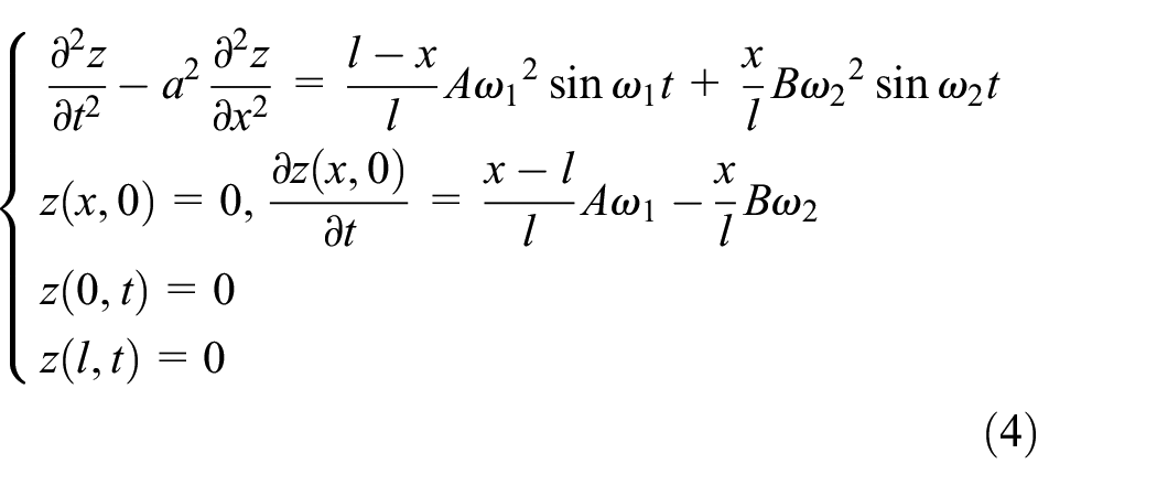
Thus, the differential equation of string vibration excited by left and right supports is:

Fourier transform
It is necessary to convert the vibration time history data at the installation position of the dropper clamp on the messenger wire into sinusoidal vibration because the vibration of catenary suspension is aperiodic vibration. 21
Any periodic signal satisfying Dirichlet condition can be expressed as infinite series of complex harmonic signal; and for aperiodic signal

in which,
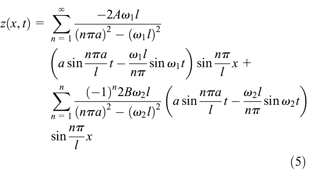
Thus, the random vibration at the installation position of the dropper clamp on the messenger wire can be expressed as a linear combination of countless sinusoidal functions with different amplitudes, frequencies and initial phases by Fourier transform.
Contactless measurement
The contact measurement method uses sensors for measurement which needs to contact with the measured object to produce load effect, it will change the physical properties of the measured object such as mass, stiffness and frequency, and affect the accuracy of measurement. The contactless measurement method can complete the measurement of the position, shape, and other parameters of the measured object without contacting and changing the physical properties of the measured object. In order to avoid disturbing the working state of the catenary suspension system, the contactless measurement method is selected. 24
At present, the commonly used contactless measurement methods include laser measurement, image measurement, and machine vision measurement. The measurement based on machine vision does not need auxiliary devices such as laser light source and complex interference light path; various measurements can be completed by using the camera through image acquisition and analysis, which is more applicable. 25 There are three camera models in machine vision: perspective projection model, orthogonal projection model, and quasi perspective projection model.
In Figure 6,


Projection model.
In the field measurement, the camera shall be perpendicular to the plane where the messenger wire and the dropper are located. The point coordinates

Contactless measurement of vibration displacement.
Lateral load solution
As shown in Figure 8, take any micro segment on the messenger wire. A horizontal tension force

Analysis of micro segment.
According to Newton’s second law, the force balance equation of micro segment is written:

Each point on the messenger wire vibrates laterally in the same plane, and the ratio of vibration amplitude to span is very small:

Equation (9) can be expressed as:

The lateral force borne by the messenger wire at any position is:

In catenary suspension, the vibration and deformation of the messenger wire are caused by the change of the dropper load caused by the lifting and deformation of the contact wire. In equation (1), the displacement at the dropper clamp caused by the dropper load is taken as the known displacement excitation to solve the vibration differential equation of the messenger wire, and the solution equation of the lateral force at any position on the messenger wire is deduced. Since the vibration of the messenger wire is caused by the change of the dropper load, the inertial force at the micro section infinitely close to the dropper clamp is also infinitely close to the dropper load.
Dropper load solution
The lateral vibration on the messenger wire caused by the change of the load borne by the dropper, so the internal load of the dropper can be obtained by analyzing the vibration state of the messenger wire. The contactless measurement process of dropper load is shown in Figure 9. Firstly, the vibration image of the dropper installation position on the messenger wire is collected through the camera, and the video is converted into vibration displacement time history data through image recognition. Secondly, the measured vibration displacement is decomposed into the linear combination of countless sinusoidal vibration signals by Fourier transform, and then the vibration state at any position on the messenger wire is analyzed by superposition principle. Finally, after solving the vibration displacement at any position of the messenger wire, the concentrated force at the installation position of the dropper is solved according to the lateral load solution theory.

Flow chart of contactless measurement of dropper load.
The Figure 10 shows the vibration displacement change curve of the installation position of the dropper clamp at the messenger when the pantograph passes through by the high-speed camera. When the leading pantograph and the trailing pantograph pass by, the messenger wire rises upward; after the pantograph passes through, the vibration decreases gradually.

Vibration displacement curve of dropper clamp on messenger wire.
The sampling frequency of the high-speed camera is 2000Hz. According to the method in the dropper load solution process, the random vibration signal of the messenger wire is decomposed into sinusoidal functions with different frequencies, different initial phases and different amplitudes according to the frequency resolution of 0.1 Hz by Fourier decomposition. And the random vibration signal of the messenger wire is reconstructed by the linear combination of the decomposed sinusoidal function, as shown in the Figure 11; the maximum absolute error between the reconstructed curve and the measured curve is 2.41×10⁻⁴mm.

Comparison of measured and reconstructed curve.
Verification of measurement method
Test platform
As shown in Figure 12, in order to verify the feasibility of the measurement method of dropper load, a contactless measurement test platform is built in the laboratory. The test platform is mainly composed of steel strand lateral vibration test desk, high-speed camera, and computer. The high-speed camera is arranged on the front of the vibration test desk to collect the vibration displacement on the steel strand; the image edge recognition software developed by the laboratory is installed on the computer to obtain the vibration displacement time history data.

Composition of contactless measurement test platform.
The relevant component models of the contactless measurement test platform are shown in Table 1. Both ends of the steel strand lateral vibration test desk are fixed supports, and the structure of steel strand is 7 × 7. The diameter of steel strand is 4 mm and the unit mass of 0.0648 kg/m. The left end of the steel strand is installed on the support through the latch, and the right end is connected with balance weight through a pulley to apply constant tension to the steel strand. The left and right end installation height of steel strand is the same. A linear motor is arranged in the middle of the fixed support. The linear motor adopts PBA series linear module with a motion range of 0–100 mm; the movement of the linear motor is transmitted to the steel strand through the arm. A force sensor is installed in series between the arm and the linear motor to record the change of the concentrated force acting on the steel strand in real time. The measurement range of the force sensor is 0–300 N, and the measurement accuracy is 0.01 N. The linear motor is controlled through the control interface on the computer, and the data measured by the force sensor is transmitted to the computer for storage in real time through the acquisition card.
Component model of contactless measurement test platform.

Tension validation
Tension is the key parameter for solving the differential equation of string vibration. The steel strand is deformed by applying a concentrated load through the linear motor. The tension on the steel strand is calculated according to the concentrated force measured by the force sensor and the equation of the steel strand.
In Figure 13, the steel strand deforms under its dead weight and the concentrated load of linear motor. According to the principle of moment balance, the resultant moment at the fixed position at the right end is zero, the moment balance equation at point


Schematic diagram of force analysis of steel strand.
in which,
The moment balance equation of steel strand at concentrated load
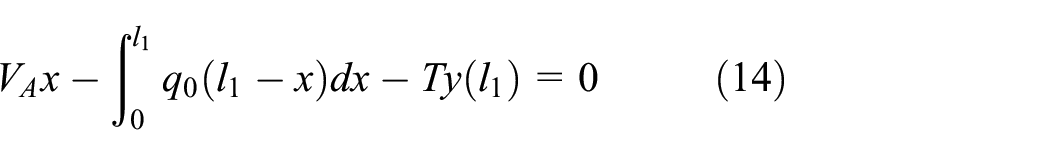
in which,
The steel strand tension can be expressed as:

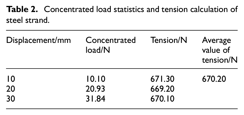
The statistics of concentrated load and tension calculation of steel strand under different displacement are detailed in Table 2. The concentrated load on steel strand under the action of linear motor is counted when the displacement is 10, 20, 30 mm, and the tension is calculated respectively. The calculated average value of tension of the steel strand is 670.20 N.
Concentrated load statistics and tension calculation of steel strand.
Impact displacement excitation
The special structure of the dropper makes it can only bear and transmit the tensile load. In the contactless measurement test, test sample with the same characteristics was made to simulate the unidirectional characteristics of the dropper are presented in Figure 14. The upper end of the sample is fixedly connected with the steel strand through a U-shaped buckle, and the lower end is connected with a dropper clamp in series and installed on the linear motor. When the linear motor moves downward, the sample is closely connected with the dropper clamp and is stretching; when the linear motor moves upward, there is a gap between the sample and the dropper clamp, which is compress.
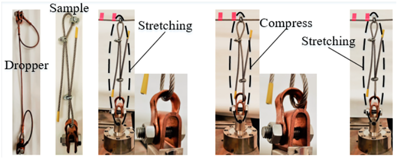
Change of sample state during vibration.
Due to the unidirectional characteristics of the sample, when the linear motor moves upward, the sample is in a relaxed state, and the steel strand will stay in the static equilibrium position. The movement of steel strand is not equal to linear motor. In order to accurately measure the displacement of steel strand at the positon of concentrated load, high-speed camera is used to monitor and record video, and the displacement time history data is obtained through image recognition.
With the assistance of auxiliary lighting system, high-speed camera is used for video sampling. Set the sampling frame rate of the camera to 1000 Hz, adjust the picture of the camera so that the target area is in the middle of the picture, start the linear motor after video recording, and set the video recording time to 10 s. Based on the characteristics of high sampling rate and high resolution of high-speed camera, the collected video stream is transmitted to the external memory in real time through the data transmission line. The recorded vibration image is shown in Figure 15, in image recognition, the distance between the points

Vibration image.
As present in Figure 16 extract the monitoring video of vibration displacement, take the same position of each frame image in the video as the origin, construct the coordinate axis, and assign coordinates to the pixels in the image. The pixel coordinates of the marked point

Edge detection of vibration image.
The coordinate sizes of mark point
The first-order change and second-order change of pixel gray value in the y-axis direction of the image are calculated by the formulas (17) and (18).


The background of the vibration image is white, and the gray value is close to 255, while the gray value of the steel strand is close to 0. Therefore, the position where the first-order change and the second-order change of the gray value along the y-axis direction are the maximum is determined as the edge point, and the pixel coordinates of the edge point are output.
According to the measured distance
In order to simulate the working state of the dropper, when the steel strand is in the dead weight balance, drive the linear motor to move downward by 20 mm to apply a static load to the steel strand; then, taking this position as the origin of the displacement movement of the linear motor. The vibration of the linear motor is set as sinusoidal vibration, which the amplitude is 30 mm and the frequency is 1 Hz. As shown in Figure 17, due to the characteristic of the sample, when the steel strand quickly recovers from the bearing state to the equilibrium position, the linear motor continues to move upward, and the steel strand will no longer move upward, but a small amplitude fluctuating vibration will be generated under the action of inertia until the attenuation is zero.

Variation of vibration displacement when the frequency is 1 Hz.
Taking the concentrated load position of the steel strand as the dividing point, the steel strand is divided into left and right sections, ignoring the initial deformation under dead weight. In the left section, the left end of the steel strand is fixed on the support of the test desk, and the right end of the steel strand is at the concentrated load position. It vibrates lateral under the action of linear motor, so the vibration differential equation of this section can be expressed as:

in which,
For the section of steel strand on the right, take the concentrated load position as the left end point and the fixed position of the test desk support as the right end point, and write the vibration differential equation as:

According to the contactless measurement process of dropper load, after obtaining the displacement of the concentrated load position, the displacement time history data can be converted into the sum of 5 × 10² sinusoidal functions with different amplitudes, different frequencies, and different initial phases by Fourier transform. And the linear superposition principle is used to solve the vibration equation of the steel strand. Then the load of steel strand at the concentrated load position is solved.
When the linear motor is in 1 Hz sinusoidal motion, monitor the displacement time history data of the movement at the concentrated load, solve the concentrated load of the steel strand, and compare it with the data measured by the force sensor. As shown in Figure 18, the measured maximum concentrated load is 54.57 N, the calculated maximum concentrated load is 54.82 N, and the calculation error is 0.46%.

Measured and calculated values when the frequency is 1 Hz.
Set the motion frequency of the linear motor to 2 Hz, when the linear motor moves upward and the steel strand reaches the static equilibrium position, due to the increase of vibration speed and inertia, the free vibration amplitude of the steel strand here is higher than that when the motion frequency of the linear motor is 1 Hz, as presented in Figure 19. The comparison between the measured and calculated values of concentrated load is shown in Figure 20. The maximum concentrated load calculated is 54.25 N, the maximum concentrated load measured by the force sensor is 54.43 N, and the calculation error is 0.33%.

Variation of vibration displacement when the frequency is 2 Hz.

Measured and calculated values when the frequency is 2 Hz.
Conclusion
Dropper is a key component in the catenary of high-speed railway and it is prone to fatigue fracture. The contactless measurement method of dropper load is concerned in this paper. The conclusions can be drawn as follows:
The dropper connects the contact wire and the messenger wire, and transmits the dead weight and vibration of the contact wire to the messenger wire to change the shape of the messenger wire. The change of messenger wire shape reflects the change of dropper load.
A contactless method is proposed to realize the accurate measurement of dropper load during the dynamic operation of pantograph and catenary. This method realizes the contactless collection of vibration data through machine vision, and solves the differential equation of messenger wire vibration based on string vibration theory, linear superposition principle, and Fourier transform, so as to obtain the dropper load.
The proposed contactless measurement method of dropper load is verified on the test platform built in the laboratory. Under the vibration excitation of different frequencies, the maximum error of contactless measurement method compared with the force sensor is less than 0.50%, which proves the correctness of the contactless measurement method.
Footnotes
Handling Editor: Chenhui Liang
Declaration of conflicting interests
The author(s) declared no potential conflicts of interest with respect to the research, authorship, and/or publication of this article.
Funding
The author(s) disclosed receipt of the following financial support for the research, authorship, and/or publication of this article: This work was supported by the China National Railway Group Limited (Q110420S04009).